В рамках геометрической оптики, распространение луча в оптически однородной среде — прямолинейное, однако в природе существует ряд явлений, где можно наблюдать отклонение от этого условия.
Дифракция – явление огибания световыми волнами встреченных препятствий. В школьной физике изучаются две дифракционные системы (системы, при прохождении луча в которых наблюдается дифракция):
- дифракция на щели (прямоугольном отверстии)
- дифракция на решётке (набор равноотстоящих друг от друга щелей)
Дифракция на щели — дифракция на прямоугольном отверстии (рис. 1).
![]()
Рис. 1. Дифракция на щели
Пусть дана плоскость со щелью, шириной , на которую под прямым углом падает пучок света А. Большинство света проходит на экран, однако часть лучей дифрагирует на краях щели (т.е. отклоняется от своего первоначального направления). Далее эти лучи интерферируют друг с другом с образованием дифракционной картины на экране (чередование ярких и тёмных областей). Рассмотрение законов интерференции достаточно сложно, поэтому ограничимся основными выводами.
Полученная дифракционная картина на экране состоит из чередующихся областей с дифракционными максимумами (максимально светлыми областями) и дифракционными минимумами (максимально тёмными областями). Эта картина симметрична относительно центрального светового пучка. Положение максимумов и минимумов описывается углом относительно вертикали, под которым они видны, и зависит от размера щели и длины волны падающего излучения. Положение этих областей можно найти используя ряд соотношений:
- для дифракционных максимумов
(1)
- где
Нулевым максимумом дифракции называется центральная точка на экране под щелью (рис. 1).
- для дифракционных минимумов
(2)
- где
Вывод: по условиям задачи необходимо выяснить: максимум или минимум дифракции необходимо найти и использовать соответствующее соотношение (1) или (2).
Дифракция на дифракционной решётке.
Дифракционной решёткой называется система, состоящая из чередующихся щелей, равноотстоящих друг от друга (рис. 2).
![]()
Рис. 2. Дифракционная решётка (лучи)
Так же, как и для щели, на экране после дифракционной решётки будет наблюдаться дифракционная картина: чередование светлых и тёмных областей. Вся картина есть результат интерференции световых лучей друг с другом, однако на картину от одной щели будет воздействовать лучи от других щелей. Тогда дифракционная картина должна зависеть от количества щелей, их размеров и близкорасположенности.
Введём новое понятие — постоянная дифракционной решётки:
(3)
- где
Тогда положения максимумов и минимумов дифракции:
- для главных дифракционных максимумов (рис. 3)
(4)
- где
![]()
Рис. 3. Дифракционная решётка (максимумы)
- для дифракционных минимумов
(5)
- где
Отдельным вопросом задач на дифракцию является вопрос о наибольшем количестве максимумов, которые можно наблюдать в текущей системе. Наибольший угол, под которым можно наблюдать максимум — , тогда, исходя из (4):
(6)
Главное помнить, что число максимумов — число, т.е. от полученного ответа необходимо брать только целую часть.
Вывод: по условиям задачи необходимо выяснить: максимум или минимум дифракции необходимо найти и использовать соответствующее соотношение (4) или (5).
Общий вывод: задачи на дифракцию должны содержать в себе словосочетания, связанные с «дифракцией». Далее разбираемся с объектом: щель или дифракционная решётка и используем соответствующие соотношения для минимума или максимума.
Дифракция света.
Автор — профессиональный репетитор, автор учебных пособий для подготовки к ЕГЭ Игорь Вячеславович Яковлев
Темы кодификатора ЕГЭ: дифракция света, дифракционная решётка.
Если на пути волны возникает препятствие, то происходит дифракция — отклонение волны от прямолинейного распространения. Это отклонение не сводится к отражению или преломлению, а также искривлению хода лучей вследствие изменения показателя преломления среды.Дифракция состоит в том, что волна огибает край препятствия и заходит в область геометрической тени.
Пусть, например, плоская волна падает на экран с достаточно узкой щелью (рис. 1). На выходе из щели возникает расходящаяся волна, и эта расходимость усиливается с уменьшением ширины щели.
 |
| Рис. 1. Дифракция на щели |
Вообще, дифракционные явления выражены тем отчётливей, чем мельче препятствие. Наиболее существенна дифракция в тех случаях, когда размер препятствия меньше или порядка длины волны. Именно такому условию должна удовлетворять ширина щели на рис. 1.
Дифракция, как и интерференция, свойственна всем видам волн — механическим и электромагнитным. Видимый свет есть частный случай электромагнитных волн; неудивительно поэтому, что можно наблюдать
дифракцию света.
Так, на рис. 2 изображена дифракционная картина, полученная в результате прохождения лазерного луча сквозь небольшое отверстие диаметром 0,2мм.
 |
| Рис. 2. Дифракция лазерного луча на отверстии |
Мы видим, как и полагается, центральное яркое пятно; совсем далеко от пятна расположена тёмная область — геометрическая тень. Но вокруг центрального пятна — вместо чёткой границы света и тени! — идут чередующиеся светлые и тёмные кольца. Чем дальше от центра, тем менее яркими становятся светлые кольца; они постепенно исчезают в области тени.
Напоминает интерференцию, не правда ли? Это она и есть; данные кольца являются интерференционными максимумами и минимумами. Какие же волны тут интерферируют? Скоро мы разберёмся с этим вопросом, а заодно и выясним, почему вообще наблюдается дифракция.
Но прежде нельзя не упомянуть самый первый классический эксперимент по интерференции света — опыт Юнга, в котором существенно использовалось явление дифракции.
Опыт Юнга.
Всякий эксперимент с интерференцией света содержит некоторый способ получения двух когерентных световых волн. В опыте с зеркалами Френеля, как вы помните, когерентными источниками являлись два изображения одного и того же источника, полученные в обоих зеркалах.
Самая простая идея, которая возникла прежде всего, состояла в следующем. Давайте проколем в куске картона два отверстия и подставим под солнечные лучи. Эти отверстия будут когерентными вторичными источниками света, поскольку первичный источник один — Солнце. Следовательно, на экране в области перекрытия пучков, расходящихся от отверстий, мы должны увидеть интерференционную картину.
Такой опыт был поставлен задолго до Юнга итальянским учёным Франческо Гримальди (который открыл дифракцию света). Интерференции, однако, не наблюдалось. Почему же? Вопрос это не очень простой, и причина заключается в том, что Солнце — не точечный, а протяжённый источник света (угловой размер Солнца равен 30 угловым минутам). Солнечный диск состоит из множества точечных источников, каждый из которых даёт на экране свою интерференционную картину. Накладываясь, эти отдельные картины «смазывают» друг друга, и в результате на экране получается равномерная освещённость области перекрытия пучков.
Но если Солнце является чрезмерно «большим», то нужно искусственно создать точечный первичный источник. С этой целью в опыте Юнга использовано маленькое предварительное отверстие (рис. 3).
 |
| Рис. 3. Схема опыта Юнга |
Плоская волна падает на первое отверстие, и за отверстием возникает световой конус, расширяющийся вследствие дифракции. Он достигает следующих двух отверстий, которые становятся источниками двух когерентных световых конусов. Вот теперь — благодаря точечности первичного источника — в области перекрытия конусов будет наблюдаться интерференционная картина!
Томас Юнг осуществил этот эксперимент, измерил ширину интерференционных полос, вывел формулу
и с помощью этой формулы впервые вычислил длины волн видимого света. Вот почему этот опыт вошёл в число самых знаменитых в истории физики.
Принцип Гюйгенса–Френеля.
Напомним формулировку принципа Гюйгенса: каждая точка, вовлечённая в волновой процесс, является источником вторичных сферических волн; эти волны распространяются от данной точки, как из центра, во все стороны и накладываются друг на друга.
Но возникает естественный вопрос: а что значит «накладываются»?
Гюйгенс свёл свой принцип к чисто геометрическому способу построения новой волновой поверхности как огибающей семейства сфер, расширяющихся от каждой точки исходной волновой поверхности. Вторичные волны Гюйгенса — это математические сферы, а не реальные волны; их суммарное действие проявляется только на огибающей, т. е. на новом положении волновой поверхности.
В таком виде принцип Гюйгенса не давал ответа на вопрос, почему в процессе распространения волны не возникает волна, идущая в обратном направлении. Не объяснёнными оставались и дифракционные явления.
Модификация принципа Гюйгенса состоялась лишь спустя 137 лет. Огюстен Френель заменил вспомогательные геометрические сферы Гюйгенса на реальные волны и предположил, что эти волны интерферируют друг с другом.
Принцип Гюйгенса–Френеля. Каждая точка волновой поверхности служит источником вторичных сферических волн. Все эти вторичные волны являются когерентными ввиду общности их происхождения от первичного источника (и, стало быть, могут интерферировать друг с другом); волновой процесс в окружающем пространстве есть результат интерференции вторичных волн.
Идея Френеля наполнила принцип Гюйгенса физическим смыслом. Вторичные волны, интерферируя, усиливают друг друга на огибающей своих волновых поверхностей в направлении «вперёд», обеспечивая дальнейшее распространение волны. А в направлении «назад» происходит их интерференция с исходной волной, наблюдается взаимное гашение, и обратная волна не возникает.
В частности, свет распространяется там, где вторичные волны взаимно усиливаются. А в местах ослабления вторичных волн мы будем видеть тёмные участки пространства.
Принцип Гюйгенса–Френеля выражает важную физическую идею: волна, удалившись от своего источника, в дальнейшем «живёт своей жизнью» и уже никак от этого источника не зависит. Захватывая новые участки пространства, волна распространяется всё дальше и дальше вследствие интерференции вторичных волн, возбуждённых в различных точках пространства по мере прохождения волны.
Как принцип Гюйгенса–Френеля объясняет явление дифракции? Почему, например, происходит дифракция на отверстии? Дело в том, что из бесконечной плоской волновой поверхности падающей волны экранное отверстие вырезает лишь маленький светящийся диск, и последующее световое поле получается в результате интерференции волн вторичных источников, расположенных уже не на всей плоскости, а лишь на этом диске. Естественно, новые волновые поверхности теперь не будут плоскими; ход лучей искривляется, и волна начинает распространяться в разных направлениях, не совпадающих с первоначальным. Волна огибает края отверстия и проникает в область геометрической тени.
Вторичные волны, испущенные различными точками вырезанного светлого диска, интерферируют друг с другом. Результат интерференции определяется разностью фаз вторичных волн и зависит от угла отклонения лучей. В результате возникает чередование интерференционных максимумов и минимумов — что мы и видели на рис. 2.
Френель не только дополнил принцип Гюйгенса важной идеей когерентности и интерференции вторичных волн, но и придумал свой знаменитый метод решения дифракционных задач, основанный на построении так называемых зон Френеля. Изучение зон Френеля не входит в школьную программу — о них вы узнаете уже в вузовском курсе физики. Здесь мы упомянем лишь, что Френелю в рамках своей теории удалось дать объяснение нашего самого первого закона геометрической оптики — закона прямолинейного распространения света.
Дифракционная решётка.
Дифракционная решётка — это оптический прибор, позволяющий получать разложение света на спектральные составляющие и измерять длины волн. Дифракционные решётки бывают прозрачными и отражательными.
Мы рассмотрим прозрачную дифракционную решётку. Она состоит из большого числа щелей ширины , разделённых промежутками ширины
(рис. 4). Свет проходит только сквозь щели; промежутки свет не пропускают. Величина
называется периодом решётки.
 |
| Рис. 4. Дифракционная решётка |
Дифракционная решётка изготавливается с помощью так называемой делительной машины, которая наносит штрихи на поверхность стекла или прозрачной плёнки. При этом штрихи оказываются непрозрачными промежутками, а нетронутые места служат щелями. Если, например, дифракционная решётка содержит 100 штрихов на миллиметр, то период такой решётки будет равен: d= 0,01 мм= 10 мкм.
Сперва мы посмотрим, как проходит сквозь решётку монохроматический свет, т. е. свет со строго определённой длиной волны. Отличным примером монохроматического света служит луч лазерной указки длина волны около 0,65 мкм).
На рис. 5 мы видим такой луч, падающий на одну из дифракционных решёток стандартного набора. Щели решётки расположены вертикально, и на экране за решёткой наблюдаются периодически расположенные вертикальные полосы.
 |
| Рис. 5. Дифракция лазерного луча на решётке |
Как вы уже поняли, это интерференционная картина. Дифракционная решётка расщепляет падающую волну на множество когерентных пучков, которые распространяются по всем направлениям и интерферируют друг с другом. Поэтому на экране мы видим чередование максимумов и минимумов интерференции — светлых и тёмных полос.
Теория дифракционной решётки весьма сложна и во всей своей полноте оказывается далеко за рамками школьной программы. Вам следует знать лишь самые элементарные вещи, связанные с одной-единственной формулой; эта формула описывает положения максимумов освещённости экрана за дифракционной решёткой.
Итак, пусть на дифракционную решётку с периодом падает плоская монохроматическая волна (рис. 6). Длина волны равна
.
 |
| Рис. 6. Дифракция на решётке |
Для большей чёткости интерференционной картины можно поставить линзу между решёткой и экраном, а экран поместить в фокальной плоскости линзы. Тогда вторичные волны, идущие параллельно от различных щелей, соберутся в одной точке экрана (побочном фокусе линзы). Если же экран расположен достаточно далеко, то особой необходимости в линзе нет — лучи, приходящие в данную точку экрана от различных щелей, будут и так почти параллельны друг другу.
Рассмотрим вторичные волны, отклоняющиеся на угол .Разность хода между двумя волнами, идущими от соседних щелей, равна маленькому катету прямоугольного треугольника с гипотенузой
; или, что то же самое, эта разность хода равна катету
треугольника
. Но угол
равен углу
, поскольку это острые углы со взаимно перпендикулярными сторонами. Следовательно, наша разность хода равна
.
Интерференционные максимумы наблюдаются в тех случаях, когда разность хода равна целому числу длин волн:
(1)
При выполнении этого условия все волны, приходящие в точку от различных щелей, будут складываться в фазе и усиливать друг друга. Линза при этом не вносит дополнительной разности хода — несмотря на то, что разные лучи проходят через линзу разными путями. Почему так получается? Мы не будем вдаваться в этот вопрос, поскольку его обсуждение выходит за рамки ЕГЭ по физике.
Формула (1) позволяет найти углы, задающие направления на максимумы:
. (2)
При получаем
Это центральный максимум, или максимум нулевого порядка.Разность хода всех вторичных волн, идущих без отклонения, равна нулю, и в центральном максимуме они складываются с нулевым сдвигом фаз. Центральный максимум — это центр дифракционной картины, самый яркий из максимумов. Дифракционная картина на экране симметрична относительно центрального максимума.
При получаем угол:
.
Этот угол задаёт направления на максимумы первого порядка. Их два, и расположены они симметрично относительно центрального максимума. Яркость в максимумах первого порядка несколько меньше, чем в центральном максимуме.
Аналогично, при имеем угол:
.
Он задаёт направления на максимумы второго порядка. Их тоже два, и они также расположены симметрично относительно центрального максимума. Яркость в максимумах второго порядка несколько меньше, чем в максимумах первого порядка.
Примерная картина направлений на максимумы первых двух порядков показана на рис. 7.
 |
| Рис. 7. Максимумы первых двух порядков |
Вообще, два симметричных максимума k-го порядка определяются углом:
. (3)
При небольших соответствующие углы обычно невелики. Например, при
мкм и
мкм максимумы первого порядка расположены под углом
.Яркость максимумов k-го порядка постепенно убывает с ростом k. Сколько всего максимумов можно увидеть? На этот вопрос легко ответить с помощью формулы (2). Ведь синус не может быть больше единицы, поэтому:
.
Используя те же числовые данные, что и выше, получим: . Следовательно, наибольший возможный порядок максимума для данной решётки равен 15.
Посмотрите ещё раз на рис. 5. На экране мы видны 11 максимумов. Это центральный максимум, а также по два максимума первого, второго, третьего, четвёртого и пятого порядков.
С помощью дифракционной решётки можно измерить неизвестную длину волны. Направляем пучок света на решётку (период которой мы знаем), измеряем угол на максимум первого
порядка, пользуемся формулой (1) и получаем:
.
Дифракционная решётка как спектральный прибор.
Выше мы рассматривали дифракцию монохроматического света, каковым является лазерный луч. Часто приходится иметь дело с немонохроматическим излучением. Оно является смесью различных монохроматических волн, которые составляют спектр данного излучения. Например, белый свет — это смесь волн всего видимого диапазона, от красного до фиолетового.
Оптический прибор называется спектральным, если он позволяет раскладывать свет на монохроматические компоненты и тем самым исследовать спектральный состав излучения. Простейший спектральный прибор вам хорошо известен — это стеклянная призма. К числу спектральных приборов относится также и дифракционная решётка.
Предположим, что на дифракционную решётку падает белый свет. Давайте вернёмся к формуле (2) и подумаем, какие выводы из неё можно сделать.
Положение центрального максимума () не зависит от длины волны. В центре дифракционной картины сойдутся с нулевой разностью хода все монохроматические составляющие белого света. Поэтому в центральном максимуме мы увидим яркую белую полосу.
А вот положения максимумов порядка определяются длиной волны. Чем меньше
, тем меньше угол
для данного
. Поэтому в максимуме k-го порядка монохроматические волны разделяются в пространстве: самой близкой к к центральному максимуму окажется фиолетовая полоса, самой далёкой — красная.
Следовательно, в каждом порядке белый свет раскладывается решёткой в спектр.
Максимумы первого порядка всех монохроматических компонент образуют спектр первого порядка; затем идут спектры второго, третьего и так далее порядков. Спектр каждого порядка имеет вид цветной полосы, в которой присутствуют все цвета радуги — от фиолетового до красного.
Дифракция белого света показана на рис. 8. Мы видим белую полосу в центральном максимуме, а по бокам — два спектра первого порядка. По мере возрастания угла отклонения цвет полос меняется от фиолетового к красному.
 |
| Рис. 8. Дифракция белого света на решётке |
Но дифракционная решётка не только позволяет наблюдать спектры, т. е. проводить качественный анализ спектрального состава излучения. Важнейшим достоинством дифракционной решётки является возможность количественного анализа — как уже говорилось выше, мы с её помощью можем измерять длины волн. При этом измерительная процедура весьма проста: фактически она сводится к измерению угла направления на максимум.
Естественными примерами дифракционных решёток, встречающихся в природе, являются перья птиц, крылья бабочек, перламутровая поверхность морской раковины. Если, прищурившись, посмотреть на солнечный свет, то можно увидеть радужную окраску вокруг ресниц.Наши ресницы действуют в данном случае как прозрачная дифракционная решётка на рис. 6, а в качестве линзы выступает оптическая система роговицы и хрусталика.
Спектральное разложение белого света, даваемое дифракционной решёткой, проще всего наблюдать, глядя на обычный компакт-диск (рис. 9). Оказывается, дорожки на поверхности диска образуют отражательную дифракционную решётку!
 |
Благодарим за то, что пользуйтесь нашими публикациями.
Информация на странице «Дифракция света.» подготовлена нашими редакторами специально, чтобы помочь вам в освоении предмета и подготовке к ЕГЭ и ОГЭ.
Чтобы успешно сдать нужные и поступить в высшее учебное заведение или техникум нужно использовать все инструменты: учеба, контрольные, олимпиады, онлайн-лекции, видеоуроки, сборники заданий.
Также вы можете воспользоваться другими статьями из разделов нашего сайта.
Публикация обновлена:
07.01.2023
Дифракция — явление отклонения световых волн от прямолинейного распространения при прохождении света мимо края препятствия. При этом лучи могут попадать в область геометрической тени от препятствия.
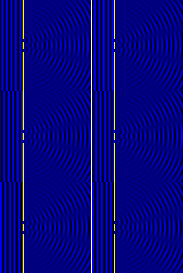
Между интерференцией и дифракцией нет существенного физического различия. Оба явления заключаются в перераспределении светового потока в результате наложения (суперпозиции) волн. По историческим причинам отклонение от закона независимости световых пучков, возникающее в результате суперпозиции когерентных волн, принято называть интерференцией волн. Отклонение от закона прямолинейного распространения света, в свою очередь, принято называть дифракцией волн.


Наблюдение дифракции осуществляется обычно по следующей схеме. На пути световой волны, распространяющейся от некоторого источника, помещается непрозрачная преграда, закрывающая часть волновой поверхности световой волны. За преградой располагается экран, на котором возникает дифракционная картина.
Различают два вида дифракции. Если источник света S и точка наблюдения P расположены от препятствия настолько далеко, что лучи, падающие на препятствие, и лучи, идущие в точку P, образуют практически параллельные пучки, говорят о дифракции в параллельных лучах или о дифракции Фраунгофера. В противном случае говорят о дифракции Френеля. Количественный критерий, позволяющий установить, какой вид дифракции имеет место, определяется величиной безразмерного параметра b2/lλ, где b – характерный размер препятствия, l – расстояние между препятствием и экраном, на котором наблюдается дифракционная картина, λ – длина волны.
Свойства дифракции:
1) Дифракция волн – характерная особенность распространения волн независимо от их природы.
2) Волны могут попадать в область геометрической тени (огибать препятствия, проникать через небольшие отверстия в экранах). Например, звук хорошо слышен за углом дома — звуковая волна его огибает. Дифракцией радиоволн вокруг поверхности Земли объясняется прием радиосигналов в диапазоне длинных и средних радиоволн за пределами прямой видимости излучающей антенны.
3) Дифракция волн зависит от соотношения между длиной волны и размером объекта, вызывающего дифракцию. В пределе при λ→0 законы волновой оптики переходят в законы геометрической оптики. Дифракция обнаруживается в тех случаях, когда размеры огибаемых препятствий соизмеримы с длиной волны.
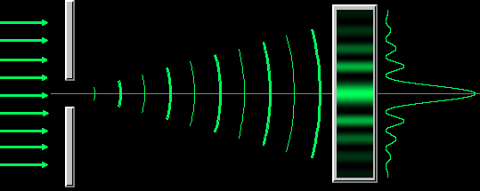
Объяснить явление дифракции можно исходя из принципа Гюйгенса-Френеля.Этот принцип представляет собой правило, объясняющее, как, исходя из положения волнового фронта в данный момент, найти новое положение волнового фронта в последующий момент времени.
Гюйгенс предложил рассматривать каждую точку среды, которой достигла волна, как источник вторичных сферических волн, распространяющихся по всем направлениям со скоростью, присущей данной среде. Поверхность, огибающая вторичные волны, представляет собой фронт волны в данный момент времени.
Френель дополнил изложенный принцип следующим положением: вторичные сферические волны являются когерентными и колебания в любой точке пространства, которой вторичные волны достигнут в момент времени t, представляют собой результат интерференции этих вторичных волн.
Принцип Гюйгенса — Френеля формулируется следующим образом:
Каждый элемент волнового фронта можно рассматривать как центр вторичного возмущения, порождающего вторичные сферические волны, а результирующее световое поле в каждой точке пространства будет определяться интерференцией этих волн.
Дифракция Фраунгофера от одной щели
Дифракция Фраунгофера наблюдается, когда источник света сильно удален от места наблюдения, в результате фронт волны можно считать плоским.
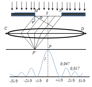
Разность хода двух волн от краев щели равна Δ = b sin φ.
Разобьем MN на отрезки длиной λ/2. Параллельно произвольному направлению луча через точки разбиения (1, 2, 3) проведем линии, которые разделят открытую часть волновой поверхности MN на участки равной ширины – зоны Френеля, параллельные краям щели. По построению ∆ – разность хода лучей от краев зон Френеля равна λ/2. Это означает, что волны, идущие от двух соседних зон при наложении погасят друг друга. Т.о., если на открытой части волновой поверхности для данного направления наблюдения уложится целое четное число зон Френеля, то для данного направления будет наблюдаться min интенсивности, т.к. зоны попарно друг друга погасят.
Четное число зон Френеля — минимум дифракции
m = 1, 2, 3…
Если число зон Френеля целое и нечетное, то в этом направлении будет наблюдаться max:
m = 0, 1, 2, 3…
Дифракционная решетка
Совокупность большого числа щелей и промежутков между ними называется дифракционной решеткой.
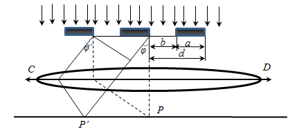
b — ширина щели;
а — ширина промежутка между щелями;
d = a + b — период решетки .

N — число щелей, приходящихся на единицу длины
Дифракционная картина на решетке определяется как интерференция волн, приходящих от всех щелей, т. е. дифракция на решетке — многолучевая интерференция. Поскольку щели разделены одинаковым расстоянием, разности хода лучей, поступающих из двух соседних щелей, будут для направления φ идентичны по всей решетке.
Δ = d sin φ
В областях, в которых существует минимум при одной щели, минимумы будут и в случае N щелей, т. е. условие первичного минимума дифракционной решетки аналогично условию минимума для одной щели:
 — условие главных минимумов.
Условие главных максимумов:

Эти максимумы расположены симметрично относительно центра (k = 0) и главного максимума.
Между основными пиками есть дополнительные очень слабые пики, интенсивность которых значительно меньше, чем у основных пиков (1/22 интенсивности ближайшего главного максимума). Количество дополнительных максимумов равно N — 2, где N — количество штрихов решетки.
Между главными максимумами будут расположены (N-1) дополнительных минимумов.
Разрешающая способность дифракционной решетки
Размер дифракционных изображений очень мал. Например, радиус центрального светлого пятна в фокальной плоскости линзы диаметром D = 5 см с фокусным расстоянием F = 50 см в монохроматическом свете с длиной волны λ = 500 нм приблизительно равен 0,006 мм. Но в высокоточных астрономических приборах реализуется дифракционный предел качества изображений. Вследствие дифракционного размытия изображения двух близких точек объекта могут оказаться неотличимыми от изображения одной точки.

Спектральной разрешающей способностью R решетки, характеризующей возможность разделения с ее помощью двух близких спектральных линий с длинами волн λ и λ + Δλ, называется отношение длины волны λ к минимально возможному значению Δλ

Пусть решетка имеет период d = 10–3 мм, ее длина L = 10 см. Тогда, N = 105 (это хорошая решетка). В спектре 2-го порядка разрешающая способность решетки оказывается равной R = 2·105. Это означает, что минимально разрешимый интервал длин волн в зеленой области спектра (λ = 550 нм) равен Δλ = λ / R ≈ 2,8·10–3 нм.
Действие оптических приборов описывается законами геометрической оптики. Согласно этим законам можно различать с помощью микроскопа сколь угодно малые детали объекта; с помощью телескопа можно установить существование двух звезд при любых малых угловых расстояниях между ними. Однако в действительности это не так, и лишь волновая теория света позволяет разобраться в причинах предела разрешающей способности оптических приборов.
Метод зон Френеля
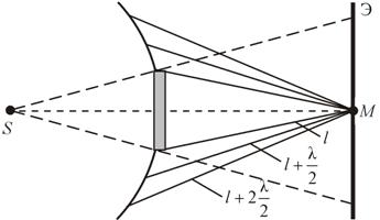
Границей первой (центральной) зоны служат точки поверхности S, находящиеся на расстоянии l + λ/2 от точки M. Точки сферы S, находящиеся на расстояниях l + 2λ/2, l + 3λ/2 , и т.д. от точки M, образуют 2, 3 и т.д. зоны Френеля.
Колебания, возбуждаемые в точке M между двумя соседними зонами, противоположны по фазе, так как разность хода от этих зон до точки M Δ = λ/2.

Поэтому при сложении этих колебаний, они должны взаимно ослаблять друг друга: A = A1 + A2 + A3 +…+ Ai.
где A – амплитуда результирующего колебания, Ai – амплитуда колебаний, возбуждаемая i-й зоной Френеля.
Величина Ai зависит от площади Si зоны и угла αi между нормалью к поверхности и прямой, направленной в точку M.
Площадь одной зоны
Отсюда видно, что площадь зоны Френеля не зависит от номера зоны i. Это значит, что при не слишком больших i площади соседних зон одинаковы.
В то же время с увеличением номера зоны возрастает угол αi и, следовательно, уменьшается интенсивность излучения зоны в направлении точки M, т.е. уменьшается амплитуда Ai. Она уменьшается также из-за увеличения расстояния до точки M.
Отсюда следует, что углы между нормалью к зоне и направлением на точку M у соседних зон примерно равны, т.е. что амплитуды волн, приходящих в точку M от соседних зон, примерно равны.
Приближенно можно считать, что амплитуда колебания Am от некоторой m-й зоны равна среднему арифметическому от амплитуд примыкающих к ней зон, т.е.

Тогда выражение для амплитуды можно записать в виде
Так как площади соседних зон одинаковы, то выражения в скобках равны нулю, значит результирующая амплитуда А = A1 /2.
Интенсивность излучения J ~ A2.
Таким образом, результирующая амплитуда, создаваемая в некоторой точке M всей сферической поверхностью, равна половине амплитуды, создаваемой одной лишь центральной зоной, а интенсивность J = J1/4 .
Так как радиус центральной зоны мал ( r1 = 0,16 мм), следовательно, можно считать, что свет от точки P до точки M распространяется прямолинейно.
Если на пути волны поставить непрозрачный экран с отверстием, оставляющим открытой только центральную зону Френеля, то амплитуда в точке M будет равна A1. Соответственно, интенсивность в точке M будет в 4 раза больше, чем при отсутствии экрана (т.к. J = 4J1 ). Интенсивность света увеличивается, если закрыть все четные зоны.
Таким образом, принцип Гюйгенса–Френеля позволяет объяснить прямолинейное распространение света в однородной среде.
Дифракция на простых объектах
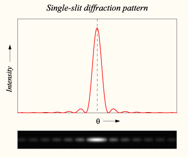
Дифракция на щели
Дифракция от круглого отверстия
Поставим на пути сферической световой волны непрозрачный экран с круглым отверстием радиуса . Экран расположен так, что перпендикуляр, опущенный из S на непрозрачный экран, попадает точно в центр отверстия.
Разобьем открытую часть волновой поверхности на зоны Френеля. Вид дифракционной картины зависит от числа зон Френеля, открываемых отверстием. Когда отверстие открывает нечетное число зон Френеля, то амплитуда (интенсивность) в точке М будет больше, чем при свободном распространении волны; если четное, то амплитуда (интенсивность) будет равна нулю.

Дифракция на круглом отверстии при открытом чётном (слева) и нечётном (справа) числе зон.
Естественно, что если r0>>λ, то никакой дифракционной картины не будет.
Дифракция от диска
Сферическая волна, распространяющаяся от точечного источника S, встречает на своем пути диск.
В центре тени светлое пятно
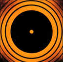
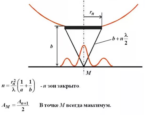
Амплитуда световых колебаний в точке M равна половине амплитуды, обусловленной первой открытой зоной. Если размер диска невелик (охватывает небольшое число зон), то действие первой зоны немногим отличается от действия центральной зоны волнового фронта. Таким образом, освещенность в точке M будет такой же, как и в отсутствие экрана. Вследствие симметрии центральная светлая точка будет окружена кольцами света и тени (вне границ геометрической тени).
Парадоксальное, на первый взгляд, заключение, в силу которого в самом центре геометрической тени может находиться светлая точка, было выдвинуто Пуассоном в 1818 г. и впоследствии было названо его именем. «Пятно Пуассона» подтверждает правильность теории Френеля.


Дифракционная
решётка,
оптический
прибор, представляющий собой совокупность
большого числа параллельных, равноотстоящих
друг от друга штрихов одинаковой формы,
нанесённых на плоскую или вогнутую
оптическую поверхность. Таким образом,
Д. р. представляет собой периодическую
структуру: штрихи с определённым и
постоянным для данной решётки профилем
повторяются через строго одинаковый
промежуток d,
называется периодом Д. р
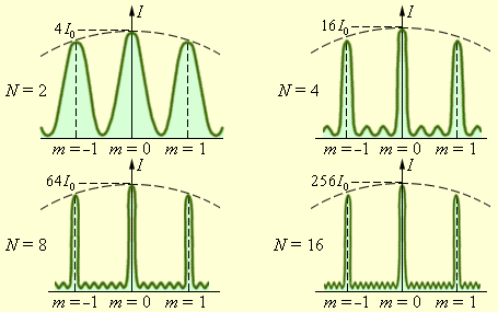
Распределение
интенсивности при дифракции
монохроматического света на решетках
с различным числом щелей. I0
– интенсивность колебаний при дифракции
света на одной щели
при дифракции света на решетке главные
максимумы чрезвычайно узки. Рис. дает
представление о том, как меняется острота
главных максимумов при увеличении числа
щелей решетки.
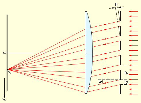
В каждой точке P на экране в фокальной
плоскости линзы соберутся лучи, которые
до линзы были параллельны между собой
и распространялись под определенным
углом θ к направлению падающей волны.
Колебание в точке P является результатом
интерференции вторичных волн, приходящих
в эту точку от разных щелей. Для того,
чтобы в точке P наблюдался интерференционный
максимум, разность хода Δ между волнами,
испущенными соседними щелями, должна
быть равна целому числу длин волн:
|
Здесь d – период
решетки, m – целое число, которое
называется порядком дифракционного
максимума. В тех точках экрана, для
которых это условие выполнено,
располагаются так называемые главные
максимумы дифракционной картины.
В
фокальной плоскости линзы расстояние
ym
от максимума нулевого порядка (m = 0)
до максимума m-го порядка при малых углах
дифракции равно
![]()
где F – фокусное
расстояние.
Следует
обратить внимание на то, что в каждой
точке фокальной плоскости линзы
происходит интерференция N волн,
приходящих в эту точку от N щелей решетки.
Это так называемая многоволновая (или
«многолучевая») интерференция.
Распределение световой энергии в
плоскости наблюдения резко отличается
от того, которое получается в обычных
«двухлучевых» интерференционных схемах.
В главные максимумы все волны приходят
в фазе, потому амплитуда колебаний
возрастает в N раз, а интенсивность в N2
раз по сравнению с колебанием, которое
возбуждает волна только от одной щели.
При смещении из
главных максимумов интенсивность
колебаний быстро спадает. Чтобы N волн
погасили друг друга, разность фаз должна
измениться на 2π / N, а не на π, как
при интерференции двух волн. На рис. 3.10.4
изображена векторная диаграмма колебаний,
возбуждаемых волнами от всех N щелей
при условии, что сдвиг фаз волн от
соседних щелей равен 2π / N, а
соответствующая разность хода равна
λ / N. Вектора, изображающие N
колебаний, образуют в этом случае
замкнутый многоугольник. Таким образом,
при переходе из главного максимума в
соседний минимум разность хода Δ = d sin θ
должна измениться на λ / N. Из этого
условия можно оценить угловую полуширину
δθ главных максимумов:
| |
Здесь
для простоты полагается, что дифракционные
углы достаточно малы. Следовательно,
![]()
где Nd – полный
размер решетки. Это соотношение находится
в полном согласии с теорией дифракции
в параллельных лучах, согласно которой
дифракционная расходимость параллельного
пучка лучей равна отношению длины волны
λ к поперечному размеру препятствия.
| |
Можно
сделать важный вывод: при дифракции
света на решетке главные максимумы
чрезвычайно узки. Рис. 1 дает
представление о том, как меняется острота
главных максимумов при увеличении числа
щелей решетки
06
Принципы Гюйгенса-Френеля. Законы
Френеля. Дифракция Френеля и дифракция
Фраунгофера. Дифракция Френеля на
круглом отверстии и диске. Метод зон
Френеля.
Принцип
Гюйгенса — Френеля —
основной
постулат волновой теории, описывающий
и объясняющий механизм распространения
волн, в частности, световых. Каждый
элемент волнового
фронта
можно рассматривать, как центр вторичного
возмущения, порождающего вторичные
сферические волны, а результирующее
световое поле в каждой точке пространства
будет определяться интерференцией этих
волн.
Дифракция
Фраунгофера
— это дифракция на отверстии, которое
для точки наблюдения открывает заметно
меньше одной зоны Френеля. Это условие
выполнено, если точка наблюдения и
источник света находятся достаточно
далеко от отверстия.
Дифракция Френеля
— это дифракция в случае, когда отверстие
открывает (или препятствие закрывает)
для точки наблюдения несколько зон
Френеля. Если открыто много зон Френеля,
то дифракцией можно пренебречь, и мы
оказываемся в приближении геометрической
оптики.
Метод зон
Френеля. Для
нахождения результата интерференции
вторичных волн Френель предложил метод
разбиения волнового фронта на зоны,
называемые зонами Френеля.
Предположим,
что источник света S (рис. 17.18) точечный
и монохроматический, а среда, в которой
распространяется свет, изотропная.
Волновой фронт в произвольный момент
времени будет иметь форму сферы радиусом
![]()
Каждая
точка на этой сферической поверхности
является вторичным источником волн.
Колебания во всех точках волновой
поверхности происходят с одинаковой
часто-той и в одинаковой фазе. Следовательно,
все эти вторичные источники когерентны.
Для нахождения амплитуды колебаний в
точке М необходимо произвести сложение
когерентных колебаний от всех вторичных
источников на волновой поверхности.
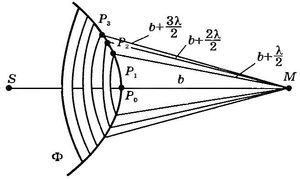
Рис.
17.18
Френель
разбил волновую поверхность Ф на
кольцевые зоны такого размера, чтобы
расстояния от краев зоны до точки М
отличались на
![]()
т.е.
![]()
Так
как разность хода от двух соседних зон
равна
то
колебания от них приходят в точку М в
противоположных фазах и при наложении
эти колебания будут взаимно ослаблять
друг друга. Поэтому амплитуда
результирующего светового колебания
в точке М будет равна
![]()
(17.5)
где
![]()
—
амплитуды колебаний, возбуждаемых 1-й,
2-й, .., m-й зонами. Френель предположил
также, что действие отдельных зон в
точке М зависит от направления
распростронения (от угла
![]()
(рис.
17.19) между нормалью
![]()
к
поверхности зоны и направлением на
точку М). С увеличением
действие
зон убывает и при углах
![]()
амплитуда
возбуждаемых вторичных волн равна 0.
Кроме того, интенсивность излучения в
направлении точки М уменьшается с ростом
и вследствие увеличения расстояния от
зоны до точки М Учитывая оба фактора,
можно записать, что
![]()
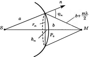
Рис.
17.19
Дифракция
на круглом отверстии.
Сферическая
волна, распространяющаяся из точечного
источника S, встречает на своем пути
экран с круглым отверстием (рис. 17.20).
Вид дифракционной картины зависит от
числа зон Френеля, укладывающихся в
отверстии. Согласно (17.5) и (17.6) в точке B
амплитуда
результирующего колебания
![]()
где знак «плюс»
соответствует нечетным m, а знак «минус»
— четным
m.
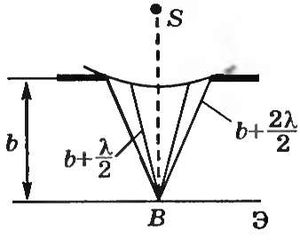
Рис.
17.20
Когда
отверстие открывает нечетное число зон
Френеля, то амплитуда колебаний в точке
В будет больше, чем при отсутствии
экрана. Если в отверстии укладывается
одна зона Френеля, то в точке В амплитуда
![]()
т.е.
вдвое больше, чем в отсутствие непрозрачного
экрана. Если в отверстии укладываются
две зоны Френеля, то их действие в точке
В
практически уничтожает друг друга из-за
интерференции. Таким образом, дифракционная
картина от круглого отверстия вблизи
точки В
будет иметь вид чередующихся темных и
светлых колец с центрами в точке В
(если m — четное, то в центре темное
кольцо, если m — нечетное — светлое
кольцо), причем интенсивность максимумов
убывает с расстоянием от центра картины.
3.
Дифракция
на диске.
Пусть диск (рис. 17.21) закрывает m первых
зон Френеля. Тогда амплитуда результирующего
колебания в точке В
равна
![]()
так как выражения, стоящие в скобках,
равны О.
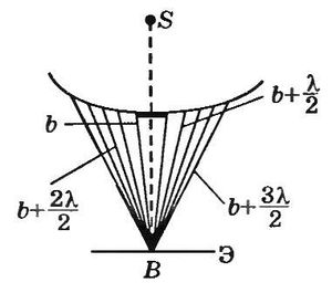
Рис.
17.21
Следовательно,
в точке В
всегда
наблюдается светлое
пятно,
соответствующее половине действия
первой открытой зоны Френеля. Центральный
максимум окружен концентрическими с
ним темными и светлыми кольцами, а
интенсивность убывает с расстоянием
от центра картины.
Соседние файлы в предмете [НЕСОРТИРОВАННОЕ]
- #
- #
- #
- #
- #
- #
- #
- #
- #
- #
- #
Not to be confused with refraction, the change in direction of a wave passing from one medium to another.
Diffraction is defined as the interference or bending of waves around the corners of an obstacle or through an aperture into the region of geometrical shadow of the obstacle/aperture. The diffracting object or aperture effectively becomes a secondary source of the propagating wave. Italian scientist Francesco Maria Grimaldi coined the word diffraction and was the first to record accurate observations of the phenomenon in 1660.[1][2]

Infinitely many points (three shown) along length d project phase contributions from the wavefront, producing a continuously varying intensity θ on the registering plate.
In classical physics, the diffraction phenomenon is described by the Huygens–Fresnel principle that treats each point in a propagating wavefront as a collection of individual spherical wavelets.[3] The characteristic bending pattern is most pronounced when a wave from a coherent source (such as a laser) encounters a slit/aperture that is comparable in size to its wavelength, as shown in the inserted image. This is due to the addition, or interference, of different points on the wavefront (or, equivalently, each wavelet) that travel by paths of different lengths to the registering surface. If there are multiple, closely spaced openings (e.g., a diffraction grating), a complex pattern of varying intensity can result.
These effects also occur when a light wave travels through a medium with a varying refractive index, or when a sound wave travels through a medium with varying acoustic impedance – all waves diffract,[4] including gravitational waves,[5] water waves, and other electromagnetic waves such as X-rays and radio waves. Furthermore, quantum mechanics also demonstrates that matter possesses wave-like properties, and hence, undergoes diffraction (which is measurable at subatomic to molecular levels).[6]
The amount of diffraction depends on the size of the gap. Diffraction is greatest when the size of the gap is similar to the wavelength of the wave. In this case, when the waves pass through the gap they become semi-circular.
History[edit]

Thomas Young’s sketch of two-slit diffraction for water waves, which he presented to the Royal Society in 1803.
The effects of diffraction of light were first carefully observed and characterized by Francesco Maria Grimaldi, who also coined the term diffraction, from the Latin diffringere, ‘to break into pieces’, referring to light breaking up into different directions. The results of Grimaldi’s observations were published posthumously in 1665.[7][8][9] Isaac Newton studied these effects and attributed them to inflexion of light rays. James Gregory (1638–1675) observed the diffraction patterns caused by a bird feather, which was effectively the first diffraction grating to be discovered.[10] Thomas Young performed a celebrated experiment in 1803 demonstrating interference from two closely spaced slits.[11] Explaining his results by interference of the waves emanating from the two different slits, he deduced that light must propagate as waves. Augustin-Jean Fresnel did more definitive studies and calculations of diffraction, made public in 1816[12] and 1818,[13] and thereby gave great support to the wave theory of light that had been advanced by Christiaan Huygens[14] and reinvigorated by Young, against Newton’s particle theory.
Mechanism[edit]
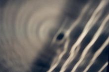
Photograph of single-slit diffraction in a circular ripple tank
In classical physics diffraction arises because of the way in which waves propagate; this is described by the Huygens–Fresnel principle and the principle of superposition of waves. The propagation of a wave can be visualized by considering every particle of the transmitted medium on a wavefront as a point source for a secondary spherical wave. The wave displacement at any subsequent point is the sum of these secondary waves. When waves are added together, their sum is determined by the relative phases as well as the amplitudes of the individual waves so that the summed amplitude of the waves can have any value between zero and the sum of the individual amplitudes. Hence, diffraction patterns usually have a series of maxima and minima.
In the modern quantum mechanical understanding of light propagation through a slit (or slits) every photon has what is known as a wavefunction. The wavefunction is determined by the physical surroundings such as slit geometry, screen distance and initial conditions when the photon is created. In important experiments (A low-intensity double-slit experiment was first performed by G. I. Taylor in 1909, see double-slit experiment) the existence of the photon’s wavefunction was demonstrated. In the quantum approach the diffraction pattern is created by the probability distribution, the observation of light and dark bands is the presence or absence of photons in these areas, where these particles were more or less likely to be detected. The quantum approach has some striking similarities to the Huygens-Fresnel principle; based on that principle, as light travels through slits and boundaries, secondary, point light sources are created near or along these obstacles, and the resulting diffraction pattern is going to be the intensity profile based on the collective interference of all these lights sources that have different optical paths. That is similar to considering the limited regions around the slits and boundaries where photons are more likely to originate from, in the quantum formalism, and calculating the probability distribution. This distribution is directly proportional to the intensity, in the classical formalism.
There are various analytical models which allow the diffracted field to be calculated, including the Kirchhoff-Fresnel diffraction equation which is derived from the wave equation,[15] the Fraunhofer diffraction approximation of the Kirchhoff equation which applies to the far field, the Fresnel diffraction approximation which applies to the near field and the Feynman path integral formulation. Most configurations cannot be solved analytically, but can yield numerical solutions through finite element and boundary element methods.
It is possible to obtain a qualitative understanding of many diffraction phenomena by considering how the relative phases of the individual secondary wave sources vary, and in particular, the conditions in which the phase difference equals half a cycle in which case waves will cancel one another out.
The simplest descriptions of diffraction are those in which the situation can be reduced to a two-dimensional problem. For water waves, this is already the case; water waves propagate only on the surface of the water. For light, we can often neglect one direction if the diffracting object extends in that direction over a distance far greater than the wavelength. In the case of light shining through small circular holes we will have to take into account the full three-dimensional nature of the problem.
-

Computer generated intensity pattern formed on a screen by diffraction from a square aperture.
-
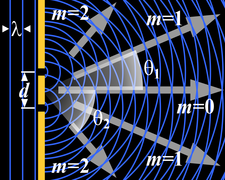
Generation of an interference pattern from two-slit diffraction.
-
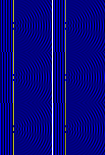
Computational model of an interference pattern from two-slit diffraction.
-
Optical diffraction pattern ( laser), (analogous to X-ray crystallography)
-
Colors seen in a spider web are partially due to diffraction, according to some analyses.[16]
Examples[edit]

Circular waves generated by diffraction from the narrow entrance of a flooded coastal quarry

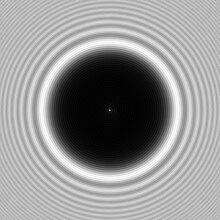
The bright spot (Arago spot) seen in the center of the shadow of a circular obstacle is due to diffraction

Diffraction spikes are diffraction patterns caused due to non-circular aperture in camera or support struts in telescope; In normal vision, diffraction through eyelashes may produce such spikes.

Simulated diffraction spikes in hexagonal telescope mirrors
The effects of diffraction are often seen in everyday life. The most striking examples of diffraction are those that involve light; for example, the closely spaced tracks on a CD or DVD act as a diffraction grating to form the familiar rainbow pattern seen when looking at a disc. This principle can be extended to engineer a grating with a structure such that it will produce any diffraction pattern desired; the hologram on a credit card is an example. Diffraction in the atmosphere by small particles can cause a bright ring to be visible around a bright light source like the sun or the moon. A shadow of a solid object, using light from a compact source, shows small fringes near its edges. The speckle pattern which is observed when laser light falls on an optically rough surface is also a diffraction phenomenon. When deli meat appears to be iridescent, that is diffraction off the meat fibers.[17] All these effects are a consequence of the fact that light propagates as a wave.
Diffraction can occur with any kind of wave. Ocean waves diffract around jetties and other obstacles. Sound waves can diffract around objects, which is why one can still hear someone calling even when hiding behind a tree.[18]
Diffraction can also be a concern in some technical applications; it sets a fundamental limit to the resolution of a camera, telescope, or microscope.
Other examples of diffraction are considered below.
Single-slit diffraction[edit]
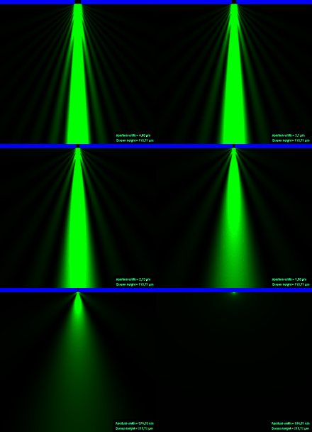
2D Single-slit diffraction with width changing animation
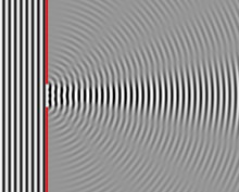
Numerical approximation of diffraction pattern from a slit of width four wavelengths with an incident plane wave. The main central beam, nulls, and phase reversals are apparent.
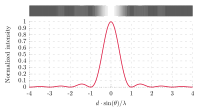
Graph and image of single-slit diffraction.
A long slit of infinitesimal width which is illuminated by light diffracts the light into a series of circular waves and the wavefront which emerges from the slit is a cylindrical wave of uniform intensity, in accordance with Huygens–Fresnel principle.
An illuminated slit that is wider than a wavelength produces interference effects in the space downstream of the slit. Assuming that the slit behaves as though it has a large number of point sources spaced evenly across the width of the slit interference effects can be calculated. The analysis of this system is simplified if we consider light of a single wavelength. If the incident light is coherent, these sources all have the same phase. Light incident at a given point in the space downstream of the slit is made up of contributions from each of these point sources and if the relative phases of these contributions vary by 
We can find the angle at which a first minimum is obtained in the diffracted light by the following reasoning. The light from a source located at the top edge of the slit interferes destructively with a source located at the middle of the slit, when the path difference between them is equal to λ/2. Similarly, the source just below the top of the slit will interfere destructively with the source located just below the middle of the slit at the same angle. We can continue this reasoning along the entire height of the slit to conclude that the condition for destructive interference for the entire slit is the same as the condition for destructive interference between two narrow slits a distance apart that is half the width of the slit. The path difference is approximately 

where
A similar argument can be used to show that if we imagine the slit to be divided into four, six, eight parts, etc., minima are obtained at angles 
where
is an integer other than zero.
There is no such simple argument to enable us to find the maxima of the diffraction pattern. The intensity profile can be calculated using the Fraunhofer diffraction equation as
where
This analysis applies only to the far field (Fraunhofer diffraction), that is, at a distance much larger than the width of the slit.
From the intensity profile above, if 


When the incident angle 
The choice of plus/minus sign depends on the definition of the incident angle 

2-slit (top) and 5-slit diffraction of red laser light

Diffraction of a red laser using a diffraction grating.

A diffraction pattern of a 633 nm laser through a grid of 150 slits
Diffraction grating[edit]
A diffraction grating is an optical component with a regular pattern. The form of the light diffracted by a grating depends on the structure of the elements and the number of elements present, but all gratings have intensity maxima at angles θm which are given by the grating equation
where
The light diffracted by a grating is found by summing the light diffracted from each of the elements, and is essentially a convolution of diffraction and interference patterns.
The figure shows the light diffracted by 2-element and 5-element gratings where the grating spacings are the same; it can be seen that the maxima are in the same position, but the detailed structures of the intensities are different.
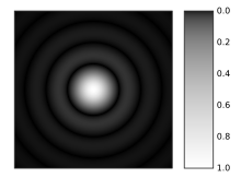
A computer-generated image of an Airy disk.
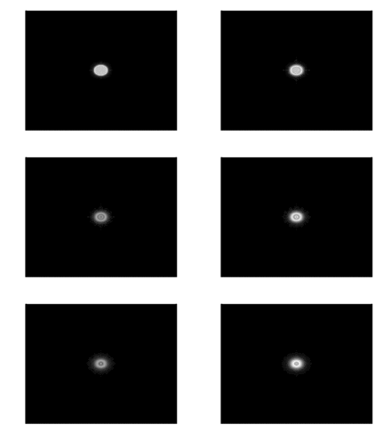
Computer generated light diffraction pattern from a circular aperture of diameter 0.5 micrometre at a wavelength of 0.6 micrometre (red-light) at distances of 0.1 cm – 1 cm in steps of 0.1 cm. One can see the image moving from the Fresnel region into the Fraunhofer region where the Airy pattern is seen.
Circular aperture[edit]
The far-field diffraction of a plane wave incident on a circular aperture is often referred to as the Airy Disk. The variation in intensity with angle is given by
,
where a is the radius of the circular aperture, k is equal to 2π/λ and J1 is a Bessel function. The smaller the aperture, the larger the spot size at a given distance, and the greater the divergence of the diffracted beams.
General aperture[edit]
The wave that emerges from a point source has amplitude 
where 
By direct substitution, the solution to this equation can be readily shown to be the scalar Green’s function, which in the spherical coordinate system (and using the physics time convention 
This solution assumes that the delta function source is located at the origin. If the source is located at an arbitrary source point, denoted by the vector 

Therefore, if an electric field, Einc(x,y) is incident on the aperture, the field produced by this aperture distribution is given by the surface integral:

On the calculation of Fraunhofer region fields
where the source point in the aperture is given by the vector
In the far field, wherein the parallel rays approximation can be employed, the Green’s function,
simplifies to
as can be seen in the figure to the right (click to enlarge).
The expression for the far-zone (Fraunhofer region) field becomes
Now, since
and
the expression for the Fraunhofer region field from a planar aperture now becomes,
Letting,
and
the Fraunhofer region field of the planar aperture assumes the form of a Fourier transform
In the far-field / Fraunhofer region, this becomes the spatial Fourier transform of the aperture distribution. Huygens’ principle when applied to an aperture simply says that the far-field diffraction pattern is the spatial Fourier transform of the aperture shape, and this is a direct by-product of using the parallel-rays approximation, which is identical to doing a plane wave decomposition of the aperture plane fields (see Fourier optics).
Propagation of a laser beam[edit]
The way in which the beam profile of a laser beam changes as it propagates is determined by diffraction. When the entire emitted beam has a planar, spatially coherent wave front, it approximates Gaussian beam profile and has the lowest divergence for a given diameter. The smaller the output beam, the quicker it diverges. It is possible to reduce the divergence of a laser beam by first expanding it with one convex lens, and then collimating it with a second convex lens whose focal point is coincident with that of the first lens. The resulting beam has a larger diameter, and hence a lower divergence. Divergence of a laser beam may be reduced below the diffraction of a Gaussian beam or even reversed to convergence if the refractive index of the propagation media increases with the light intensity.[19] This may result in a self-focusing effect.
When the wave front of the emitted beam has perturbations, only the transverse coherence length (where the wave front perturbation is less than 1/4 of the wavelength) should be considered as a Gaussian beam diameter when determining the divergence of the laser beam. If the transverse coherence length in the vertical direction is higher than in horizontal, the laser beam divergence will be lower in the vertical direction than in the horizontal.
Diffraction-limited imaging[edit]
The ability of an imaging system to resolve detail is ultimately limited by diffraction. This is because a plane wave incident on a circular lens or mirror is diffracted as described above. The light is not focused to a point but forms an Airy disk having a central spot in the focal plane whose radius (as measured to the first null) is
where λ is the wavelength of the light and N is the f-number (focal length f divided by aperture diameter D) of the imaging optics; this is strictly accurate for N≫1 (paraxial case). In object space, the corresponding angular resolution is
where D is the diameter of the entrance pupil of the imaging lens (e.g., of a telescope’s main mirror).
Two point sources will each produce an Airy pattern – see the photo of a binary star. As the point sources move closer together, the patterns will start to overlap, and ultimately they will merge to form a single pattern, in which case the two point sources cannot be resolved in the image. The Rayleigh criterion specifies that two point sources are considered «resolved» if the separation of the two images is at least the radius of the Airy disk, i.e. if the first minimum of one coincides with the maximum of the other.
Thus, the larger the aperture of the lens compared to the wavelength, the finer the resolution of an imaging system. This is one reason astronomical telescopes require large objectives, and why microscope objectives require a large numerical aperture (large aperture diameter compared to working distance) in order to obtain the highest possible resolution.
Speckle patterns[edit]
The speckle pattern seen when using a laser pointer is another diffraction phenomenon. It is a result of the superposition of many waves with different phases, which are produced when a laser beam illuminates a rough surface. They add together to give a resultant wave whose amplitude, and therefore intensity, varies randomly.
Babinet’s principle[edit]
Babinet’s principle is a useful theorem stating that the diffraction pattern from an opaque body is identical to that from a hole of the same size and shape, but with differing intensities. This means that the interference conditions of a single obstruction would be the same as that of a single slit.
«Knife edge»[edit]
The knife-edge effect or knife-edge diffraction is a truncation of a portion of the incident radiation that strikes a sharp well-defined obstacle, such as a mountain range or the wall of a building.
The knife-edge effect is explained by Huygens–Fresnel principle, which states that a well-defined obstruction to an electromagnetic wave acts as a secondary source, and creates a new wavefront. This new wavefront propagates into the geometric shadow area of the obstacle.
Knife-edge diffraction is an outgrowth of the «half-plane problem», originally solved by Arnold Sommerfeld using a plane wave spectrum formulation. A generalization of the half-plane problem is the «wedge problem», solvable as a boundary value problem in cylindrical coordinates. The solution in cylindrical coordinates was then extended to the optical regime by Joseph B. Keller, who introduced the notion of diffraction coefficients through his geometrical theory of diffraction (GTD). Pathak and Kouyoumjian extended the (singular) Keller coefficients via the uniform theory of diffraction (UTD).
-

Diffraction on a sharp metallic edge
-

Diffraction on a soft aperture, with a gradient of conductivity over the image width
Patterns[edit]

The upper half of this image shows a diffraction pattern of He-Ne laser beam on an elliptic aperture. The lower half is its 2D Fourier transform approximately reconstructing the shape of the aperture.
Several qualitative observations can be made of diffraction in general:
- The angular spacing of the features in the diffraction pattern is inversely proportional to the dimensions of the object causing the diffraction. In other words: The smaller the diffracting object, the ‘wider’ the resulting diffraction pattern, and vice versa. (More precisely, this is true of the sines of the angles.)
- The diffraction angles are invariant under scaling; that is, they depend only on the ratio of the wavelength to the size of the diffracting object.
- When the diffracting object has a periodic structure, for example in a diffraction grating, the features generally become sharper. The third figure, for example, shows a comparison of a double-slit pattern with a pattern formed by five slits, both sets of slits having the same spacing, between the center of one slit and the next.
Particle diffraction[edit]
According to quantum theory every particle exhibits wave properties. In particular, massive particles can interfere with themselves and therefore diffract. Diffraction of electrons and neutrons stood as one of the powerful arguments in favor of quantum mechanics. The wavelength associated with a particle is the de Broglie wavelength
where h is Planck’s constant and p is the momentum of the particle (mass × velocity for slow-moving particles).
For most macroscopic objects, this wavelength is so short that it is not meaningful to assign a wavelength to them. A sodium atom traveling at about 30,000 m/s would have a De Broglie wavelength of about 50 pico meters.
Because the wavelength for even the smallest of macroscopic objects is extremely small, diffraction of matter waves is only visible for small particles, like electrons, neutrons, atoms and small molecules. The short wavelength of these matter waves makes them ideally suited to study the atomic crystal structure of solids and large molecules like proteins.
Relatively larger molecules like buckyballs were also shown to diffract.[20]
Bragg diffraction[edit]
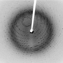
Following Bragg’s law, each dot (or reflection) in this diffraction pattern forms from the constructive interference of X-rays passing through a crystal. The data can be used to determine the crystal’s atomic structure.
Diffraction from a three-dimensional periodic structure such as atoms in a crystal is called Bragg diffraction.
It is similar to what occurs when waves are scattered from a diffraction grating. Bragg diffraction is a consequence of interference between waves reflecting from different crystal planes.
The condition of constructive interference is given by Bragg’s law:
where
- λ is the wavelength,
- d is the distance between crystal planes,
- θ is the angle of the diffracted wave.
- and m is an integer known as the order of the diffracted beam.
Bragg diffraction may be carried out using either electromagnetic radiation of very short wavelength like X-rays or matter waves like neutrons (and electrons) whose wavelength is on the order of (or much smaller than) the atomic spacing.[21] The pattern produced gives information of the separations of crystallographic planes d, allowing one to deduce the crystal structure. Diffraction contrast, in electron microscopes and x-topography devices in particular, is also a powerful tool for examining individual defects and local strain fields in crystals.
Coherence[edit]
The description of diffraction relies on the interference of waves emanating from the same source taking different paths to the same point on a screen. In this description, the difference in phase between waves that took different paths is only dependent on the effective path length. This does not take into account the fact that waves that arrive at the screen at the same time were emitted by the source at different times. The initial phase with which the source emits waves can change over time in an unpredictable way. This means that waves emitted by the source at times that are too far apart can no longer form a constant interference pattern since the relation between their phases is no longer time independent.[22]: 919
The length over which the phase in a beam of light is correlated, is called the coherence length. In order for interference to occur, the path length difference must be smaller than the coherence length. This is sometimes referred to as spectral coherence, as it is related to the presence of different frequency components in the wave. In the case of light emitted by an atomic transition, the coherence length is related to the lifetime of the excited state from which the atom made its transition.[23]: 71–74 [24]: 314–316
If waves are emitted from an extended source, this can lead to incoherence in the transversal direction. When looking at a cross section of a beam of light, the length over which the phase is correlated is called the transverse coherence length. In the case of Young’s double slit experiment, this would mean that if the transverse coherence length is smaller than the spacing between the two slits, the resulting pattern on a screen would look like two single slit diffraction patterns.[23]: 74–79
In the case of particles like electrons, neutrons, and atoms, the coherence length is related to the spatial extent of the wave function that describes the particle.[25]: 107
Applications[edit]
Diffraction before destruction[edit]
A new way to image single biological particles has emerged over the last few years, utilising the bright X-rays generated by X-ray free electron lasers. These femtosecond-duration pulses will allow for the (potential) imaging of single biological macromolecules. Due to these short pulses, radiation damage can be outrun, and diffraction patterns of single biological macromolecules will be able to be obtained.[26][27]
See also[edit]
- Angle-sensitive pixel
- Atmospheric diffraction
- Brocken spectre
- Cloud iridescence
- Coherent diffraction imaging
- Diffraction from slits
- Diffraction spike
- Diffraction vs. interference
- Diffractometer
- Dynamical theory of diffraction
- Fraunhofer diffraction
- Fresnel imager
- Fresnel number
- Fresnel zone
- Point spread function
- Powder diffraction
- Quasioptics
- Refraction
- Reflection
- Schaefer–Bergmann diffraction
- Thinned-array curse
- X-ray scattering techniques
References[edit]
- ^ Francesco Maria Grimaldi, Physico mathesis de lumine, coloribus, et iride, aliisque annexis libri duo (Bologna («Bonomia»), Italy: Vittorio Bonati, 1665), page 2 Archived 2016-12-01 at the Wayback Machine:
Original : Nobis alius quartus modus illuxit, quem nunc proponimus, vocamusque; diffractionem, quia advertimus lumen aliquando diffringi, hoc est partes eius multiplici dissectione separatas per idem tamen medium in diversa ulterius procedere, eo modo, quem mox declarabimus.
Translation : It has illuminated for us another, fourth way, which we now make known and call «diffraction» [i.e., shattering], because we sometimes observe light break up; that is, that parts of the compound [i.e., the beam of light], separated by division, advance farther through the medium but in different [directions], as we will soon show.
- ^ Cajori, Florian «A History of Physics in its Elementary Branches, including the evolution of physical laboratories.» Archived 2016-12-01 at the Wayback Machine MacMillan Company, New York 1899
- ^ Wireless Communications: Principles and Practice, Prentice Hall communications engineering and emerging technologies series, T. S. Rappaport, Prentice Hall, 2002 pg 126
- ^ Suryanarayana, C.; Norton, M. Grant (29 June 2013). X-Ray Diffraction: A Practical Approach. Springer Science & Business Media. p. 14. ISBN 978-1-4899-0148-4. Retrieved 7 January 2023.
- ^ Kokkotas, Kostas D. (2003). «Gravitational Wave Physics». Encyclopedia of Physical Science and Technology: 67–85. doi:10.1016/B0-12-227410-5/00300-8. ISBN 9780122274107.
- ^ Juffmann, Thomas; Milic, Adriana; Müllneritsch, Michael; Asenbaum, Peter; Tsukernik, Alexander; Tüxen, Jens; Mayor, Marcel; Cheshnovsky, Ori; Arndt, Markus (25 March 2012). «Real-time single-molecule imaging of quantum interference». Nature Nanotechnology. 7 (5): 297–300. arXiv:1402.1867. Bibcode:2012NatNa…7..297J. doi:10.1038/nnano.2012.34. ISSN 1748-3395. PMID 22447163. S2CID 5918772.
- ^ Francesco Maria Grimaldi, Physico-mathesis de lumine, coloribus, et iride, aliisque adnexis … [The physical mathematics of light, color, and the rainbow, and other things appended …] (Bologna («Bonomia»), (Italy): Vittorio Bonati, 1665), pp. 1–11 Archived 2016-12-01 at the Wayback Machine: «Propositio I. Lumen propagatur seu diffunditur non solum directe, refracte, ac reflexe, sed etiam alio quodam quarto modo, diffracte.» (Proposition 1. Light propagates or spreads not only in a straight line, by refraction, and by reflection, but also by a somewhat different fourth way: by diffraction.) On p. 187, Grimaldi also discusses the interference of light from two sources: «Propositio XXII. Lumen aliquando per sui communicationem reddit obscuriorem superficiem corporis aliunde, ac prius illustratam.» (Proposition 22. Sometimes light, as a result of its transmission, renders dark a body’s surface, [which had been] previously illuminated by another [source].)
- ^ Jean Louis Aubert (1760). Memoires pour l’histoire des sciences et des beaux arts. Paris: Impr. de S. A. S.; Chez E. Ganeau. pp. 149.
grimaldi diffraction 0–1800.
- ^ Sir David Brewster (1831). A Treatise on Optics. London: Longman, Rees, Orme, Brown & Green and John Taylor. pp. 95.
- ^ Letter from James Gregory to John Collins, dated 13 May 1673. Reprinted in: Correspondence of Scientific Men of the Seventeenth Century …, ed. Stephen Jordan Rigaud (Oxford, England: Oxford University Press, 1841), vol. 2, pp. 251–255, especially p. 254 Archived 2016-12-01 at the Wayback Machine.
- ^ Thomas Young (1 January 1804). «The Bakerian Lecture: Experiments and calculations relative to physical optics». Philosophical Transactions of the Royal Society of London. 94: 1–16. Bibcode:1804RSPT…94….1Y. doi:10.1098/rstl.1804.0001. S2CID 110408369.. (Note: This lecture was presented before the Royal Society on 24 November 1803.)
- ^ Fresnel, Augustin-Jean (1816), «Mémoire sur la diffraction de la lumière» («Memoir on the diffraction of light»), Annales de Chimie et de Physique, vol. 1, pp. 239–81 (March 1816); reprinted as «Deuxième Mémoire…» («Second Memoir…») in Oeuvres complètes d’Augustin Fresnel, vol. 1 (Paris: Imprimerie Impériale, 1866), pp. 89–122. (Revision of the «First Memoir» submitted on 15 October 1815.)
- ^ Fresnel, Augustin-Jean (1818), «Mémoire sur la diffraction de la lumière» («Memoir on the diffraction of light»), deposited 29 July 1818, «crowned» 15 March 1819, published in Mémoires de l’Académie Royale des Sciences de l’Institut de France, vol. V (for 1821 & 1822, printed 1826), pp. 339–475; reprinted in Oeuvres complètes d’Augustin Fresnel, vol. 1 (Paris: Imprimerie Impériale, 1866), pp. 247–364; partly translated as «Fresnel’s prize memoir on the diffraction of light», in H. Crew (ed.), The Wave Theory of Light: Memoirs by Huygens, Young and Fresnel, American Book Company, 1900, pp. 81–144. (First published, as extracts only, in Annales de Chimie et de Physique, vol. 11 (1819), pp. 246–96, 337–78.)
- ^ Christiaan Huygens, Traité de la lumiere … Archived 2016-06-16 at the Wayback Machine (Leiden, Netherlands: Pieter van der Aa, 1690), Chapter 1. From p. 15 Archived 2016-12-01 at the Wayback Machine: «J’ay donc monstré de quelle façon l’on peut concevoir que la lumiere s’etend successivement par des ondes spheriques, … « (I have thus shown in what manner one can imagine that light propagates successively by spherical waves, … ) (Note: Huygens published his Traité in 1690; however, in the preface to his book, Huygens states that in 1678 he first communicated his book to the French Royal Academy of Sciences.)
- ^ Baker, B.B. & Copson, E.T. (1939), The Mathematical Theory of Huygens’ Principle, Oxford, pp. 36–40.
- ^ Dietrich Zawischa. «Optical effects on spider webs». Retrieved 21 September 2007.
- ^ Arumugam, Nadia (9 September 2013). «Food Explainer: Why Is Some Deli Meat Iridescent?». Slate. The Slate Group. Archived from the original on 10 September 2013. Retrieved 9 September 2013.
- ^
Andrew Norton (2000). Dynamic fields and waves of physics. CRC Press. p. 102. ISBN 978-0-7503-0719-2. - ^ Chiao, R. Y.; Garmire, E.; Townes, C. H. (1964). «Self-Trapping of Optical Beams». Physical Review Letters. 13 (15): 479–482. Bibcode:1964PhRvL..13..479C. doi:10.1103/PhysRevLett.13.479.
- ^ Brezger, B.; Hackermüller, L.; Uttenthaler, S.; Petschinka, J.; Arndt, M.; Zeilinger, A. (February 2002). «Matter–Wave Interferometer for Large Molecules» (reprint). Physical Review Letters. 88 (10): 100404. arXiv:quant-ph/0202158. Bibcode:2002PhRvL..88j0404B. doi:10.1103/PhysRevLett.88.100404. PMID 11909334. S2CID 19793304. Archived (PDF) from the original on 13 August 2007. Retrieved 30 April 2007.
- ^ John M. Cowley (1975) Diffraction physics (North-Holland, Amsterdam) ISBN 0-444-10791-6
- ^ Halliday, David; Resnick, Robert; Walker, Jerl (2005), Fundamental of Physics (7th ed.), USA: John Wiley and Sons, Inc., ISBN 978-0-471-23231-5
- ^ a b Grant R. Fowles (1975). Introduction to Modern Optics. Courier Corporation. ISBN 978-0-486-65957-2.
- ^ Hecht, Eugene (2002), Optics (4th ed.), United States of America: Addison Wesley, ISBN 978-0-8053-8566-3
- ^ Ayahiko Ichimiya; Philip I. Cohen (13 December 2004). Reflection High-Energy Electron Diffraction. Cambridge University Press. ISBN 978-0-521-45373-8. Archived from the original on 16 July 2017.
- ^ Neutze, Richard; Wouts, Remco; van der Spoel, David; Weckert, Edgar; Hajdu, Janos (August 2000). «Potential for biomolecular imaging with femtosecond X-ray pulses». Nature. 406 (6797): 752–757. Bibcode:2000Natur.406..752N. doi:10.1038/35021099. ISSN 1476-4687. PMID 10963603. S2CID 4300920.
- ^ Chapman, Henry N.; Caleman, Carl; Timneanu, Nicusor (17 July 2014). «Diffraction before destruction». Philosophical Transactions of the Royal Society B: Biological Sciences. 369 (1647): 20130313. doi:10.1098/rstb.2013.0313. PMC 4052855. PMID 24914146.
External links[edit]
- The Feynman Lectures on Physics Vol. I Ch. 30: Diffraction
- «Scattering and diffraction». Crystallography. International Union of Crystallography.
Not to be confused with refraction, the change in direction of a wave passing from one medium to another.
Diffraction is defined as the interference or bending of waves around the corners of an obstacle or through an aperture into the region of geometrical shadow of the obstacle/aperture. The diffracting object or aperture effectively becomes a secondary source of the propagating wave. Italian scientist Francesco Maria Grimaldi coined the word diffraction and was the first to record accurate observations of the phenomenon in 1660.[1][2]

Infinitely many points (three shown) along length d project phase contributions from the wavefront, producing a continuously varying intensity θ on the registering plate.
In classical physics, the diffraction phenomenon is described by the Huygens–Fresnel principle that treats each point in a propagating wavefront as a collection of individual spherical wavelets.[3] The characteristic bending pattern is most pronounced when a wave from a coherent source (such as a laser) encounters a slit/aperture that is comparable in size to its wavelength, as shown in the inserted image. This is due to the addition, or interference, of different points on the wavefront (or, equivalently, each wavelet) that travel by paths of different lengths to the registering surface. If there are multiple, closely spaced openings (e.g., a diffraction grating), a complex pattern of varying intensity can result.
These effects also occur when a light wave travels through a medium with a varying refractive index, or when a sound wave travels through a medium with varying acoustic impedance – all waves diffract,[4] including gravitational waves,[5] water waves, and other electromagnetic waves such as X-rays and radio waves. Furthermore, quantum mechanics also demonstrates that matter possesses wave-like properties, and hence, undergoes diffraction (which is measurable at subatomic to molecular levels).[6]
The amount of diffraction depends on the size of the gap. Diffraction is greatest when the size of the gap is similar to the wavelength of the wave. In this case, when the waves pass through the gap they become semi-circular.
History[edit]

Thomas Young’s sketch of two-slit diffraction for water waves, which he presented to the Royal Society in 1803.
The effects of diffraction of light were first carefully observed and characterized by Francesco Maria Grimaldi, who also coined the term diffraction, from the Latin diffringere, ‘to break into pieces’, referring to light breaking up into different directions. The results of Grimaldi’s observations were published posthumously in 1665.[7][8][9] Isaac Newton studied these effects and attributed them to inflexion of light rays. James Gregory (1638–1675) observed the diffraction patterns caused by a bird feather, which was effectively the first diffraction grating to be discovered.[10] Thomas Young performed a celebrated experiment in 1803 demonstrating interference from two closely spaced slits.[11] Explaining his results by interference of the waves emanating from the two different slits, he deduced that light must propagate as waves. Augustin-Jean Fresnel did more definitive studies and calculations of diffraction, made public in 1816[12] and 1818,[13] and thereby gave great support to the wave theory of light that had been advanced by Christiaan Huygens[14] and reinvigorated by Young, against Newton’s particle theory.
Mechanism[edit]

Photograph of single-slit diffraction in a circular ripple tank
In classical physics diffraction arises because of the way in which waves propagate; this is described by the Huygens–Fresnel principle and the principle of superposition of waves. The propagation of a wave can be visualized by considering every particle of the transmitted medium on a wavefront as a point source for a secondary spherical wave. The wave displacement at any subsequent point is the sum of these secondary waves. When waves are added together, their sum is determined by the relative phases as well as the amplitudes of the individual waves so that the summed amplitude of the waves can have any value between zero and the sum of the individual amplitudes. Hence, diffraction patterns usually have a series of maxima and minima.
In the modern quantum mechanical understanding of light propagation through a slit (or slits) every photon has what is known as a wavefunction. The wavefunction is determined by the physical surroundings such as slit geometry, screen distance and initial conditions when the photon is created. In important experiments (A low-intensity double-slit experiment was first performed by G. I. Taylor in 1909, see double-slit experiment) the existence of the photon’s wavefunction was demonstrated. In the quantum approach the diffraction pattern is created by the probability distribution, the observation of light and dark bands is the presence or absence of photons in these areas, where these particles were more or less likely to be detected. The quantum approach has some striking similarities to the Huygens-Fresnel principle; based on that principle, as light travels through slits and boundaries, secondary, point light sources are created near or along these obstacles, and the resulting diffraction pattern is going to be the intensity profile based on the collective interference of all these lights sources that have different optical paths. That is similar to considering the limited regions around the slits and boundaries where photons are more likely to originate from, in the quantum formalism, and calculating the probability distribution. This distribution is directly proportional to the intensity, in the classical formalism.
There are various analytical models which allow the diffracted field to be calculated, including the Kirchhoff-Fresnel diffraction equation which is derived from the wave equation,[15] the Fraunhofer diffraction approximation of the Kirchhoff equation which applies to the far field, the Fresnel diffraction approximation which applies to the near field and the Feynman path integral formulation. Most configurations cannot be solved analytically, but can yield numerical solutions through finite element and boundary element methods.
It is possible to obtain a qualitative understanding of many diffraction phenomena by considering how the relative phases of the individual secondary wave sources vary, and in particular, the conditions in which the phase difference equals half a cycle in which case waves will cancel one another out.
The simplest descriptions of diffraction are those in which the situation can be reduced to a two-dimensional problem. For water waves, this is already the case; water waves propagate only on the surface of the water. For light, we can often neglect one direction if the diffracting object extends in that direction over a distance far greater than the wavelength. In the case of light shining through small circular holes we will have to take into account the full three-dimensional nature of the problem.
-

Computer generated intensity pattern formed on a screen by diffraction from a square aperture.
-

Generation of an interference pattern from two-slit diffraction.
-

Computational model of an interference pattern from two-slit diffraction.
-
Optical diffraction pattern ( laser), (analogous to X-ray crystallography)
-
Colors seen in a spider web are partially due to diffraction, according to some analyses.[16]
Examples[edit]

Circular waves generated by diffraction from the narrow entrance of a flooded coastal quarry


The bright spot (Arago spot) seen in the center of the shadow of a circular obstacle is due to diffraction

Diffraction spikes are diffraction patterns caused due to non-circular aperture in camera or support struts in telescope; In normal vision, diffraction through eyelashes may produce such spikes.

Simulated diffraction spikes in hexagonal telescope mirrors
The effects of diffraction are often seen in everyday life. The most striking examples of diffraction are those that involve light; for example, the closely spaced tracks on a CD or DVD act as a diffraction grating to form the familiar rainbow pattern seen when looking at a disc. This principle can be extended to engineer a grating with a structure such that it will produce any diffraction pattern desired; the hologram on a credit card is an example. Diffraction in the atmosphere by small particles can cause a bright ring to be visible around a bright light source like the sun or the moon. A shadow of a solid object, using light from a compact source, shows small fringes near its edges. The speckle pattern which is observed when laser light falls on an optically rough surface is also a diffraction phenomenon. When deli meat appears to be iridescent, that is diffraction off the meat fibers.[17] All these effects are a consequence of the fact that light propagates as a wave.
Diffraction can occur with any kind of wave. Ocean waves diffract around jetties and other obstacles. Sound waves can diffract around objects, which is why one can still hear someone calling even when hiding behind a tree.[18]
Diffraction can also be a concern in some technical applications; it sets a fundamental limit to the resolution of a camera, telescope, or microscope.
Other examples of diffraction are considered below.
Single-slit diffraction[edit]

2D Single-slit diffraction with width changing animation

Numerical approximation of diffraction pattern from a slit of width four wavelengths with an incident plane wave. The main central beam, nulls, and phase reversals are apparent.

Graph and image of single-slit diffraction.
A long slit of infinitesimal width which is illuminated by light diffracts the light into a series of circular waves and the wavefront which emerges from the slit is a cylindrical wave of uniform intensity, in accordance with Huygens–Fresnel principle.
An illuminated slit that is wider than a wavelength produces interference effects in the space downstream of the slit. Assuming that the slit behaves as though it has a large number of point sources spaced evenly across the width of the slit interference effects can be calculated. The analysis of this system is simplified if we consider light of a single wavelength. If the incident light is coherent, these sources all have the same phase. Light incident at a given point in the space downstream of the slit is made up of contributions from each of these point sources and if the relative phases of these contributions vary by 
We can find the angle at which a first minimum is obtained in the diffracted light by the following reasoning. The light from a source located at the top edge of the slit interferes destructively with a source located at the middle of the slit, when the path difference between them is equal to λ/2. Similarly, the source just below the top of the slit will interfere destructively with the source located just below the middle of the slit at the same angle. We can continue this reasoning along the entire height of the slit to conclude that the condition for destructive interference for the entire slit is the same as the condition for destructive interference between two narrow slits a distance apart that is half the width of the slit. The path difference is approximately 

where
A similar argument can be used to show that if we imagine the slit to be divided into four, six, eight parts, etc., minima are obtained at angles 
where
is an integer other than zero.
There is no such simple argument to enable us to find the maxima of the diffraction pattern. The intensity profile can be calculated using the Fraunhofer diffraction equation as
where
This analysis applies only to the far field (Fraunhofer diffraction), that is, at a distance much larger than the width of the slit.
From the intensity profile above, if 


When the incident angle 
The choice of plus/minus sign depends on the definition of the incident angle 

2-slit (top) and 5-slit diffraction of red laser light

Diffraction of a red laser using a diffraction grating.

A diffraction pattern of a 633 nm laser through a grid of 150 slits
Diffraction grating[edit]
A diffraction grating is an optical component with a regular pattern. The form of the light diffracted by a grating depends on the structure of the elements and the number of elements present, but all gratings have intensity maxima at angles θm which are given by the grating equation
where
The light diffracted by a grating is found by summing the light diffracted from each of the elements, and is essentially a convolution of diffraction and interference patterns.
The figure shows the light diffracted by 2-element and 5-element gratings where the grating spacings are the same; it can be seen that the maxima are in the same position, but the detailed structures of the intensities are different.

A computer-generated image of an Airy disk.

Computer generated light diffraction pattern from a circular aperture of diameter 0.5 micrometre at a wavelength of 0.6 micrometre (red-light) at distances of 0.1 cm – 1 cm in steps of 0.1 cm. One can see the image moving from the Fresnel region into the Fraunhofer region where the Airy pattern is seen.
Circular aperture[edit]
The far-field diffraction of a plane wave incident on a circular aperture is often referred to as the Airy Disk. The variation in intensity with angle is given by
,
where a is the radius of the circular aperture, k is equal to 2π/λ and J1 is a Bessel function. The smaller the aperture, the larger the spot size at a given distance, and the greater the divergence of the diffracted beams.
General aperture[edit]
The wave that emerges from a point source has amplitude 
where 
By direct substitution, the solution to this equation can be readily shown to be the scalar Green’s function, which in the spherical coordinate system (and using the physics time convention 
This solution assumes that the delta function source is located at the origin. If the source is located at an arbitrary source point, denoted by the vector 

Therefore, if an electric field, Einc(x,y) is incident on the aperture, the field produced by this aperture distribution is given by the surface integral:

On the calculation of Fraunhofer region fields
where the source point in the aperture is given by the vector
In the far field, wherein the parallel rays approximation can be employed, the Green’s function,
simplifies to
as can be seen in the figure to the right (click to enlarge).
The expression for the far-zone (Fraunhofer region) field becomes
Now, since
and
the expression for the Fraunhofer region field from a planar aperture now becomes,
Letting,
and
the Fraunhofer region field of the planar aperture assumes the form of a Fourier transform
In the far-field / Fraunhofer region, this becomes the spatial Fourier transform of the aperture distribution. Huygens’ principle when applied to an aperture simply says that the far-field diffraction pattern is the spatial Fourier transform of the aperture shape, and this is a direct by-product of using the parallel-rays approximation, which is identical to doing a plane wave decomposition of the aperture plane fields (see Fourier optics).
Propagation of a laser beam[edit]
The way in which the beam profile of a laser beam changes as it propagates is determined by diffraction. When the entire emitted beam has a planar, spatially coherent wave front, it approximates Gaussian beam profile and has the lowest divergence for a given diameter. The smaller the output beam, the quicker it diverges. It is possible to reduce the divergence of a laser beam by first expanding it with one convex lens, and then collimating it with a second convex lens whose focal point is coincident with that of the first lens. The resulting beam has a larger diameter, and hence a lower divergence. Divergence of a laser beam may be reduced below the diffraction of a Gaussian beam or even reversed to convergence if the refractive index of the propagation media increases with the light intensity.[19] This may result in a self-focusing effect.
When the wave front of the emitted beam has perturbations, only the transverse coherence length (where the wave front perturbation is less than 1/4 of the wavelength) should be considered as a Gaussian beam diameter when determining the divergence of the laser beam. If the transverse coherence length in the vertical direction is higher than in horizontal, the laser beam divergence will be lower in the vertical direction than in the horizontal.
Diffraction-limited imaging[edit]
The ability of an imaging system to resolve detail is ultimately limited by diffraction. This is because a plane wave incident on a circular lens or mirror is diffracted as described above. The light is not focused to a point but forms an Airy disk having a central spot in the focal plane whose radius (as measured to the first null) is
where λ is the wavelength of the light and N is the f-number (focal length f divided by aperture diameter D) of the imaging optics; this is strictly accurate for N≫1 (paraxial case). In object space, the corresponding angular resolution is
where D is the diameter of the entrance pupil of the imaging lens (e.g., of a telescope’s main mirror).
Two point sources will each produce an Airy pattern – see the photo of a binary star. As the point sources move closer together, the patterns will start to overlap, and ultimately they will merge to form a single pattern, in which case the two point sources cannot be resolved in the image. The Rayleigh criterion specifies that two point sources are considered «resolved» if the separation of the two images is at least the radius of the Airy disk, i.e. if the first minimum of one coincides with the maximum of the other.
Thus, the larger the aperture of the lens compared to the wavelength, the finer the resolution of an imaging system. This is one reason astronomical telescopes require large objectives, and why microscope objectives require a large numerical aperture (large aperture diameter compared to working distance) in order to obtain the highest possible resolution.
Speckle patterns[edit]
The speckle pattern seen when using a laser pointer is another diffraction phenomenon. It is a result of the superposition of many waves with different phases, which are produced when a laser beam illuminates a rough surface. They add together to give a resultant wave whose amplitude, and therefore intensity, varies randomly.
Babinet’s principle[edit]
Babinet’s principle is a useful theorem stating that the diffraction pattern from an opaque body is identical to that from a hole of the same size and shape, but with differing intensities. This means that the interference conditions of a single obstruction would be the same as that of a single slit.
«Knife edge»[edit]
The knife-edge effect or knife-edge diffraction is a truncation of a portion of the incident radiation that strikes a sharp well-defined obstacle, such as a mountain range or the wall of a building.
The knife-edge effect is explained by Huygens–Fresnel principle, which states that a well-defined obstruction to an electromagnetic wave acts as a secondary source, and creates a new wavefront. This new wavefront propagates into the geometric shadow area of the obstacle.
Knife-edge diffraction is an outgrowth of the «half-plane problem», originally solved by Arnold Sommerfeld using a plane wave spectrum formulation. A generalization of the half-plane problem is the «wedge problem», solvable as a boundary value problem in cylindrical coordinates. The solution in cylindrical coordinates was then extended to the optical regime by Joseph B. Keller, who introduced the notion of diffraction coefficients through his geometrical theory of diffraction (GTD). Pathak and Kouyoumjian extended the (singular) Keller coefficients via the uniform theory of diffraction (UTD).
-

Diffraction on a sharp metallic edge
-

Diffraction on a soft aperture, with a gradient of conductivity over the image width
Patterns[edit]

The upper half of this image shows a diffraction pattern of He-Ne laser beam on an elliptic aperture. The lower half is its 2D Fourier transform approximately reconstructing the shape of the aperture.
Several qualitative observations can be made of diffraction in general:
- The angular spacing of the features in the diffraction pattern is inversely proportional to the dimensions of the object causing the diffraction. In other words: The smaller the diffracting object, the ‘wider’ the resulting diffraction pattern, and vice versa. (More precisely, this is true of the sines of the angles.)
- The diffraction angles are invariant under scaling; that is, they depend only on the ratio of the wavelength to the size of the diffracting object.
- When the diffracting object has a periodic structure, for example in a diffraction grating, the features generally become sharper. The third figure, for example, shows a comparison of a double-slit pattern with a pattern formed by five slits, both sets of slits having the same spacing, between the center of one slit and the next.
Particle diffraction[edit]
According to quantum theory every particle exhibits wave properties. In particular, massive particles can interfere with themselves and therefore diffract. Diffraction of electrons and neutrons stood as one of the powerful arguments in favor of quantum mechanics. The wavelength associated with a particle is the de Broglie wavelength
where h is Planck’s constant and p is the momentum of the particle (mass × velocity for slow-moving particles).
For most macroscopic objects, this wavelength is so short that it is not meaningful to assign a wavelength to them. A sodium atom traveling at about 30,000 m/s would have a De Broglie wavelength of about 50 pico meters.
Because the wavelength for even the smallest of macroscopic objects is extremely small, diffraction of matter waves is only visible for small particles, like electrons, neutrons, atoms and small molecules. The short wavelength of these matter waves makes them ideally suited to study the atomic crystal structure of solids and large molecules like proteins.
Relatively larger molecules like buckyballs were also shown to diffract.[20]
Bragg diffraction[edit]

Following Bragg’s law, each dot (or reflection) in this diffraction pattern forms from the constructive interference of X-rays passing through a crystal. The data can be used to determine the crystal’s atomic structure.
Diffraction from a three-dimensional periodic structure such as atoms in a crystal is called Bragg diffraction.
It is similar to what occurs when waves are scattered from a diffraction grating. Bragg diffraction is a consequence of interference between waves reflecting from different crystal planes.
The condition of constructive interference is given by Bragg’s law:
where
- λ is the wavelength,
- d is the distance between crystal planes,
- θ is the angle of the diffracted wave.
- and m is an integer known as the order of the diffracted beam.
Bragg diffraction may be carried out using either electromagnetic radiation of very short wavelength like X-rays or matter waves like neutrons (and electrons) whose wavelength is on the order of (or much smaller than) the atomic spacing.[21] The pattern produced gives information of the separations of crystallographic planes d, allowing one to deduce the crystal structure. Diffraction contrast, in electron microscopes and x-topography devices in particular, is also a powerful tool for examining individual defects and local strain fields in crystals.
Coherence[edit]
The description of diffraction relies on the interference of waves emanating from the same source taking different paths to the same point on a screen. In this description, the difference in phase between waves that took different paths is only dependent on the effective path length. This does not take into account the fact that waves that arrive at the screen at the same time were emitted by the source at different times. The initial phase with which the source emits waves can change over time in an unpredictable way. This means that waves emitted by the source at times that are too far apart can no longer form a constant interference pattern since the relation between their phases is no longer time independent.[22]: 919
The length over which the phase in a beam of light is correlated, is called the coherence length. In order for interference to occur, the path length difference must be smaller than the coherence length. This is sometimes referred to as spectral coherence, as it is related to the presence of different frequency components in the wave. In the case of light emitted by an atomic transition, the coherence length is related to the lifetime of the excited state from which the atom made its transition.[23]: 71–74 [24]: 314–316
If waves are emitted from an extended source, this can lead to incoherence in the transversal direction. When looking at a cross section of a beam of light, the length over which the phase is correlated is called the transverse coherence length. In the case of Young’s double slit experiment, this would mean that if the transverse coherence length is smaller than the spacing between the two slits, the resulting pattern on a screen would look like two single slit diffraction patterns.[23]: 74–79
In the case of particles like electrons, neutrons, and atoms, the coherence length is related to the spatial extent of the wave function that describes the particle.[25]: 107
Applications[edit]
Diffraction before destruction[edit]
A new way to image single biological particles has emerged over the last few years, utilising the bright X-rays generated by X-ray free electron lasers. These femtosecond-duration pulses will allow for the (potential) imaging of single biological macromolecules. Due to these short pulses, radiation damage can be outrun, and diffraction patterns of single biological macromolecules will be able to be obtained.[26][27]
See also[edit]
- Angle-sensitive pixel
- Atmospheric diffraction
- Brocken spectre
- Cloud iridescence
- Coherent diffraction imaging
- Diffraction from slits
- Diffraction spike
- Diffraction vs. interference
- Diffractometer
- Dynamical theory of diffraction
- Fraunhofer diffraction
- Fresnel imager
- Fresnel number
- Fresnel zone
- Point spread function
- Powder diffraction
- Quasioptics
- Refraction
- Reflection
- Schaefer–Bergmann diffraction
- Thinned-array curse
- X-ray scattering techniques
References[edit]
- ^ Francesco Maria Grimaldi, Physico mathesis de lumine, coloribus, et iride, aliisque annexis libri duo (Bologna («Bonomia»), Italy: Vittorio Bonati, 1665), page 2 Archived 2016-12-01 at the Wayback Machine:
Original : Nobis alius quartus modus illuxit, quem nunc proponimus, vocamusque; diffractionem, quia advertimus lumen aliquando diffringi, hoc est partes eius multiplici dissectione separatas per idem tamen medium in diversa ulterius procedere, eo modo, quem mox declarabimus.
Translation : It has illuminated for us another, fourth way, which we now make known and call «diffraction» [i.e., shattering], because we sometimes observe light break up; that is, that parts of the compound [i.e., the beam of light], separated by division, advance farther through the medium but in different [directions], as we will soon show.
- ^ Cajori, Florian «A History of Physics in its Elementary Branches, including the evolution of physical laboratories.» Archived 2016-12-01 at the Wayback Machine MacMillan Company, New York 1899
- ^ Wireless Communications: Principles and Practice, Prentice Hall communications engineering and emerging technologies series, T. S. Rappaport, Prentice Hall, 2002 pg 126
- ^ Suryanarayana, C.; Norton, M. Grant (29 June 2013). X-Ray Diffraction: A Practical Approach. Springer Science & Business Media. p. 14. ISBN 978-1-4899-0148-4. Retrieved 7 January 2023.
- ^ Kokkotas, Kostas D. (2003). «Gravitational Wave Physics». Encyclopedia of Physical Science and Technology: 67–85. doi:10.1016/B0-12-227410-5/00300-8. ISBN 9780122274107.
- ^ Juffmann, Thomas; Milic, Adriana; Müllneritsch, Michael; Asenbaum, Peter; Tsukernik, Alexander; Tüxen, Jens; Mayor, Marcel; Cheshnovsky, Ori; Arndt, Markus (25 March 2012). «Real-time single-molecule imaging of quantum interference». Nature Nanotechnology. 7 (5): 297–300. arXiv:1402.1867. Bibcode:2012NatNa…7..297J. doi:10.1038/nnano.2012.34. ISSN 1748-3395. PMID 22447163. S2CID 5918772.
- ^ Francesco Maria Grimaldi, Physico-mathesis de lumine, coloribus, et iride, aliisque adnexis … [The physical mathematics of light, color, and the rainbow, and other things appended …] (Bologna («Bonomia»), (Italy): Vittorio Bonati, 1665), pp. 1–11 Archived 2016-12-01 at the Wayback Machine: «Propositio I. Lumen propagatur seu diffunditur non solum directe, refracte, ac reflexe, sed etiam alio quodam quarto modo, diffracte.» (Proposition 1. Light propagates or spreads not only in a straight line, by refraction, and by reflection, but also by a somewhat different fourth way: by diffraction.) On p. 187, Grimaldi also discusses the interference of light from two sources: «Propositio XXII. Lumen aliquando per sui communicationem reddit obscuriorem superficiem corporis aliunde, ac prius illustratam.» (Proposition 22. Sometimes light, as a result of its transmission, renders dark a body’s surface, [which had been] previously illuminated by another [source].)
- ^ Jean Louis Aubert (1760). Memoires pour l’histoire des sciences et des beaux arts. Paris: Impr. de S. A. S.; Chez E. Ganeau. pp. 149.
grimaldi diffraction 0–1800.
- ^ Sir David Brewster (1831). A Treatise on Optics. London: Longman, Rees, Orme, Brown & Green and John Taylor. pp. 95.
- ^ Letter from James Gregory to John Collins, dated 13 May 1673. Reprinted in: Correspondence of Scientific Men of the Seventeenth Century …, ed. Stephen Jordan Rigaud (Oxford, England: Oxford University Press, 1841), vol. 2, pp. 251–255, especially p. 254 Archived 2016-12-01 at the Wayback Machine.
- ^ Thomas Young (1 January 1804). «The Bakerian Lecture: Experiments and calculations relative to physical optics». Philosophical Transactions of the Royal Society of London. 94: 1–16. Bibcode:1804RSPT…94….1Y. doi:10.1098/rstl.1804.0001. S2CID 110408369.. (Note: This lecture was presented before the Royal Society on 24 November 1803.)
- ^ Fresnel, Augustin-Jean (1816), «Mémoire sur la diffraction de la lumière» («Memoir on the diffraction of light»), Annales de Chimie et de Physique, vol. 1, pp. 239–81 (March 1816); reprinted as «Deuxième Mémoire…» («Second Memoir…») in Oeuvres complètes d’Augustin Fresnel, vol. 1 (Paris: Imprimerie Impériale, 1866), pp. 89–122. (Revision of the «First Memoir» submitted on 15 October 1815.)
- ^ Fresnel, Augustin-Jean (1818), «Mémoire sur la diffraction de la lumière» («Memoir on the diffraction of light»), deposited 29 July 1818, «crowned» 15 March 1819, published in Mémoires de l’Académie Royale des Sciences de l’Institut de France, vol. V (for 1821 & 1822, printed 1826), pp. 339–475; reprinted in Oeuvres complètes d’Augustin Fresnel, vol. 1 (Paris: Imprimerie Impériale, 1866), pp. 247–364; partly translated as «Fresnel’s prize memoir on the diffraction of light», in H. Crew (ed.), The Wave Theory of Light: Memoirs by Huygens, Young and Fresnel, American Book Company, 1900, pp. 81–144. (First published, as extracts only, in Annales de Chimie et de Physique, vol. 11 (1819), pp. 246–96, 337–78.)
- ^ Christiaan Huygens, Traité de la lumiere … Archived 2016-06-16 at the Wayback Machine (Leiden, Netherlands: Pieter van der Aa, 1690), Chapter 1. From p. 15 Archived 2016-12-01 at the Wayback Machine: «J’ay donc monstré de quelle façon l’on peut concevoir que la lumiere s’etend successivement par des ondes spheriques, … « (I have thus shown in what manner one can imagine that light propagates successively by spherical waves, … ) (Note: Huygens published his Traité in 1690; however, in the preface to his book, Huygens states that in 1678 he first communicated his book to the French Royal Academy of Sciences.)
- ^ Baker, B.B. & Copson, E.T. (1939), The Mathematical Theory of Huygens’ Principle, Oxford, pp. 36–40.
- ^ Dietrich Zawischa. «Optical effects on spider webs». Retrieved 21 September 2007.
- ^ Arumugam, Nadia (9 September 2013). «Food Explainer: Why Is Some Deli Meat Iridescent?». Slate. The Slate Group. Archived from the original on 10 September 2013. Retrieved 9 September 2013.
- ^
Andrew Norton (2000). Dynamic fields and waves of physics. CRC Press. p. 102. ISBN 978-0-7503-0719-2. - ^ Chiao, R. Y.; Garmire, E.; Townes, C. H. (1964). «Self-Trapping of Optical Beams». Physical Review Letters. 13 (15): 479–482. Bibcode:1964PhRvL..13..479C. doi:10.1103/PhysRevLett.13.479.
- ^ Brezger, B.; Hackermüller, L.; Uttenthaler, S.; Petschinka, J.; Arndt, M.; Zeilinger, A. (February 2002). «Matter–Wave Interferometer for Large Molecules» (reprint). Physical Review Letters. 88 (10): 100404. arXiv:quant-ph/0202158. Bibcode:2002PhRvL..88j0404B. doi:10.1103/PhysRevLett.88.100404. PMID 11909334. S2CID 19793304. Archived (PDF) from the original on 13 August 2007. Retrieved 30 April 2007.
- ^ John M. Cowley (1975) Diffraction physics (North-Holland, Amsterdam) ISBN 0-444-10791-6
- ^ Halliday, David; Resnick, Robert; Walker, Jerl (2005), Fundamental of Physics (7th ed.), USA: John Wiley and Sons, Inc., ISBN 978-0-471-23231-5
- ^ a b Grant R. Fowles (1975). Introduction to Modern Optics. Courier Corporation. ISBN 978-0-486-65957-2.
- ^ Hecht, Eugene (2002), Optics (4th ed.), United States of America: Addison Wesley, ISBN 978-0-8053-8566-3
- ^ Ayahiko Ichimiya; Philip I. Cohen (13 December 2004). Reflection High-Energy Electron Diffraction. Cambridge University Press. ISBN 978-0-521-45373-8. Archived from the original on 16 July 2017.
- ^ Neutze, Richard; Wouts, Remco; van der Spoel, David; Weckert, Edgar; Hajdu, Janos (August 2000). «Potential for biomolecular imaging with femtosecond X-ray pulses». Nature. 406 (6797): 752–757. Bibcode:2000Natur.406..752N. doi:10.1038/35021099. ISSN 1476-4687. PMID 10963603. S2CID 4300920.
- ^ Chapman, Henry N.; Caleman, Carl; Timneanu, Nicusor (17 July 2014). «Diffraction before destruction». Philosophical Transactions of the Royal Society B: Biological Sciences. 369 (1647): 20130313. doi:10.1098/rstb.2013.0313. PMC 4052855. PMID 24914146.
External links[edit]
- The Feynman Lectures on Physics Vol. I Ch. 30: Diffraction
- «Scattering and diffraction». Crystallography. International Union of Crystallography.
5.5. Дифракционная решетка
Широкое распространение в научном эксперименте и технике получили дифракционные решетки, которые представляют собой множество параллельных, расположенных на равных расстояниях одинаковых щелей, разделенных равными по ширине непрозрачными промежутками. Дифракционные решетки изготавливаются с помощью делительной машины, наносящей штрихи (царапины) на стекле или другом прозрачном материале. Там, где проведена царапина, материал становится непрозрачным, а промежутки между ними остаются прозрачными и фактически играют роль щелей.
Рассмотрим сначала дифракцию света от решетки на примере двух щелей. (При увеличении числа щелей дифракционные максимумы становятся лишь более узкими, более яркими и отчетливыми.)
Пусть а — ширина щели, a b — ширина непрозрачного промежутка (рис. 5.6).

Рис. 5.6. Дифракция от двух щелей
Период дифракционной решетки — это расстояние между серединами соседних щелей:

Разность хода двух крайних лучей равна

Если разность хода равна нечетному числу полуволн

то свет, посылаемый двумя щелями, вследствие интерференции волн будет взаимно гаситься. Условие минимумов имеет вид

Эти минимумы называются дополнительными.
Если разность хода равна четному числу полуволн

то волны, посылаемые каждой щелью, будет взаимно усиливать друг друга. Условие интерференционных максимумов с учетом (5.36) имеет вид

Это формула для главных максимумов дифракционной решетки.
Кроме того, в тех направлениях, в которых ни одна из щелей не распространяет свет, он не будет распространяться и при двух щелях, то есть главные минимумы решетки будут наблюдаться в направлениях, определяемых условием (5.21) для одной щели:

Если дифракционная решетка состоит из N щелей (современные решетки, применяемые в приборах для спектрального анализа, имеют до 200 000 штрихов, и период d = 0.8 мкм, то есть порядка 12 000 штрихов на 1 см), то условием главных минимумов является, как и в случае двух щелей, соотношение (5.41), условием главных максимумов — соотношение (5.40), а условие дополнительных минимумов имеет вид

Здесь k’ может принимать все целочисленные значения, кроме 0, N, 2N, . . Следовательно, в случае N щелей между двумя главными максимумами располагается (N–1) дополнительных минимумов, разделенных вторичными максимумами, создающими относительно слабый фон.
Положение главных максимумов зависит от длины волны l. Поэтому при пропускании через решетку белого света все максимумы, кроме центрального, разлагаются в спектр, фиолетовый конец которого обращен к центру дифракционной картины, а красный — наружу. Таким образом, дифракционная решетка представляет собой спектральный прибор. Заметим, что в то время как спектральная призма сильнее всего отклоняет фиолетовые лучи, дифракционная решетка, наоборот, сильнее отклоняет красные лучи.
Важной характеристикой всякого спектрального прибора является разрешающая способность.
Разрешающая способность спектрального прибора — это безразмерная величина
Дифракция света
В рамках геометрической оптики, распространение луча в оптически однородной среде — прямолинейное, однако в природе существует ряд явлений, где можно наблюдать отклонение от этого условия.
Дифракция – явление огибания световыми волнами встреченных препятствий. В школьной физике изучаются две дифракционные системы (системы, при прохождении луча в которых наблюдается дифракция):
- дифракция на щели (прямоугольном отверстии)
- дифракция на решётке (набор равноотстоящих друг от друга щелей)
Дифракция на щели — дифракция на прямоугольном отверстии (рис. 1).

Рис. 1. Дифракция на щели
Пусть дана плоскость со щелью, шириной , на которую под прямым углом падает пучок света А. Большинство света проходит на экран, однако часть лучей дифрагирует на краях щели (т.е. отклоняется от своего первоначального направления). Далее эти лучи интерферируют друг с другом с образованием дифракционной картины на экране (чередование ярких и тёмных областей). Рассмотрение законов интерференции достаточно сложно, поэтому ограничимся основными выводами.
Полученная дифракционная картина на экране состоит из чередующихся областей с дифракционными максимумами (максимально светлыми областями) и дифракционными минимумами (максимально тёмными областями). Эта картина симметрична относительно центрального светового пучка. Положение максимумов и минимумов описывается углом относительно вертикали, под которым они видны, и зависит от размера щели и длины волны падающего излучения. Положение этих областей можно найти используя ряд соотношений:
- для дифракционных максимумов
- где
- — ширина щели,
- — угол между вертикалью и направлением на максимум,
- — порядок максимума (счётчик),
- — длина волны света.
Нулевым максимумом дифракции называется центральная точка на экране под щелью (рис. 1).
- для дифракционных минимумов
- где
- — ширина щели,
- — угол между вертикалью и направлением на минимум,
- — порядок минимума (счётчик),
- — длина волны света.
Вывод: по условиям задачи необходимо выяснить: максимум или минимум дифракции необходимо найти и использовать соответствующее соотношение (1) или (2).
Дифракция на дифракционной решётке.
Дифракционной решёткой называется система, состоящая из чередующихся щелей, равноотстоящих друг от друга (рис. 2).

Рис. 2. Дифракционная решётка (лучи)
Так же, как и для щели, на экране после дифракционной решётки будет наблюдаться дифракционная картина: чередование светлых и тёмных областей. Вся картина есть результат интерференции световых лучей друг с другом, однако на картину от одной щели будет воздействовать лучи от других щелей. Тогда дифракционная картина должна зависеть от количества щелей, их размеров и близкорасположенности.
Введём новое понятие — постоянная дифракционной решётки:
- где
- — постоянная дифракционной решётки,
- — расстояние между щелями,
- — ширина щели.
Тогда положения максимумов и минимумов дифракции:
- для главных дифракционных максимумов (рис. 3)
- где
- — постоянная дифракционной решётки,
- — угол между вертикалью и направлением на максимум.
- — порядок максимума (счётчик),

Рис. 3. Дифракционная решётка (максимумы)
- для дифракционных минимумов
- где
- — ширина щели,
- — угол между вертикалью и направлением на минимум,
- — порядок минимума (счётчик),
- — длина волны света.
Отдельным вопросом задач на дифракцию является вопрос о наибольшем количестве максимумов, которые можно наблюдать в текущей системе. Наибольший угол, под которым можно наблюдать максимум — , тогда, исходя из (4):
Главное помнить, что число максимумов — число, т.е. от полученного ответа необходимо брать только целую часть.
Вывод: по условиям задачи необходимо выяснить: максимум или минимум дифракции необходимо найти и использовать соответствующее соотношение (4) или (5).
Общий вывод: задачи на дифракцию должны содержать в себе словосочетания, связанные с «дифракцией». Далее разбираемся с объектом: щель или дифракционная решётка и используем соответствующие соотношения для минимума или максимума.
Уравнение максимумов интерференции для дифракционной решетки
Дифракция — явление отклонения световых волн от прямолинейного распространения при прохождении света мимо края препятствия. При этом лучи могут попадать в область геометрической тени от препятствия.

Между интерференцией и дифракцией нет существенного физического различия. Оба явления заключаются в перераспределении светового потока в результате наложения (суперпозиции) волн. По историческим причинам отклонение от закона независимости световых пучков, возникающее в результате суперпозиции когерентных волн, принято называть интерференцией волн . Отклонение от закона прямолинейного распространения света, в свою очередь, принято называть дифракцией волн .


Наблюдение дифракции осуществляется обычно по следующей схеме. На пути световой волны, распространяющейся от некоторого источника, помещается непрозрачная преграда, закрывающая часть волновой поверхности световой волны. За преградой располагается экран, на котором возникает дифракционная картина.
Различают два вида дифракции. Если источник света S и точка наблюдения P расположены от препятствия настолько далеко, что лучи, падающие на препятствие, и лучи, идущие в точку P, образуют практически параллельные пучки, говорят о дифракции в параллельных лучах или о дифракции Фраунгофера . В противном случае говорят о дифракции Френеля . Количественный критерий, позволяющий установить, какой вид дифракции имеет место, определяется величиной безразмерного параметра b 2 /lλ, где b – характерный размер препятствия, l – расстояние между препятствием и экраном, на котором наблюдается дифракционная картина, λ – длина волны.
Свойства дифракции:
1) Дифракция волн – характерная особенность распространения волн независимо от их природы.
2) Волны могут попадать в область геометрической тени (огибать препятствия, проникать через небольшие отверстия в экранах). Например, звук хорошо слышен за углом дома — звуковая волна его огибает. Дифракцией радиоволн вокруг поверхности Земли объясняется прием радиосигналов в диапазоне длинных и средних радиоволн за пределами прямой видимости излучающей антенны.
3) Дифракция волн зависит от соотношения между длиной волны и размером объекта, вызывающего дифракцию. В пределе при λ→0 законы волновой оптики переходят в законы геометрической оптики. Дифракция обнаруживается в тех случаях, когда размеры огибаемых препятствий соизмеримы с длиной волны.

Объяснить явление дифракции можно исходя из принципа Гюйгенса-Френеля .Этот принцип представляет собой правило, объясняющее, как, исходя из положения волнового фронта в данный момент, найти новое положение волнового фронта в последующий момент времени.
Гюйгенс предложил рассматривать каждую точку среды, которой достигла волна, как источник вторичных сферических волн, распространяющихся по всем направлениям со скоростью, присущей данной среде . Поверхность, огибающая вторичные волны, представляет собой фронт волны в данный момент времени.
Френель дополнил изложенный принцип следующим положением: вторичные сферические волны являются когерентными и колебания в любой точке пространства, которой вторичные волны достигнут в момент времени t, представляют собой результат интерференции этих вторичных волн .
Принцип Гюйгенса — Френеля формулируется следующим образом:
Каждый элемент волнового фронта можно рассматривать как центр вторичного возмущения, порождающего вторичные сферические волны, а результирующее световое поле в каждой точке пространства будет определяться интерференцией этих волн.
Дифракция Фраунгофера от одной щели
Дифракция Фраунгофера наблюдается, когда источник света сильно удален от места наблюдения, в результате фронт волны можно считать плоским.

Разность хода двух волн от краев щели равна Δ = b sin φ .
Разобьем MN на отрезки длиной λ/2. Параллельно произвольному направлению луча через точки разбиения (1, 2, 3) проведем линии, которые разделят открытую часть волновой поверхности MN на участки равной ширины – зоны Френеля, параллельные краям щели. По построению ∆ – разность хода лучей от краев зон Френеля равна λ/2. Это означает, что волны, идущие от двух соседних зон при наложении погасят друг друга. Т.о., если на открытой части волновой поверхности для данного направления наблюдения уложится целое четное число зон Френеля, то для данного направления будет наблюдаться min интенсивности, т.к. зоны попарно друг друга погасят.
Четное число зон Френеля — минимум дифракции
Если число зон Френеля целое и нечетное, то в этом направлении будет наблюдаться max:
Дифракционная решетка
Совокупность большого числа щелей и промежутков между ними называется дифракционной решеткой.

а — ширина промежутка между щелями;

N — число щелей, приходящихся на единицу длины
Дифракционная картина на решетке определяется как интерференция волн, приходящих от всех щелей, т. е. дифракция на решетке — многолучевая интерференция. Поскольку щели разделены одинаковым расстоянием, разности хода лучей, поступающих из двух соседних щелей, будут для направления φ идентичны по всей решетке.
В областях, в которых существует минимум при одной щели, минимумы будут и в случае N щелей, т. е. условие первичного минимума дифракционной решетки аналогично условию минимума для одной щели:
 — условие главных минимумов.
Условие главных максимумов :

Эти максимумы расположены симметрично относительно центра (k = 0) и главного максимума.
Между основными пиками есть дополнительные очень слабые пики, интенсивность которых значительно меньше, чем у основных пиков (1/22 интенсивности ближайшего главного максимума). Количество дополнительных максимумов равно N — 2, где N — количество штрихов решетки.
Между главными максимумами будут расположены (N-1) дополнительных минимумов.
Разрешающая способность дифракционной решетки
Размер дифракционных изображений очень мал. Например, радиус центрального светлого пятна в фокальной плоскости линзы диаметром D = 5 см с фокусным расстоянием F = 50 см в монохроматическом свете с длиной волны λ = 500 нм приблизительно равен 0,006 мм. Но в высокоточных астрономических приборах реализуется дифракционный предел качества изображений. Вследствие дифракционного размытия изображения двух близких точек объекта могут оказаться неотличимыми от изображения одной точки.

Спектральной разрешающей способностью R решетки, характеризующей возможность разделения с ее помощью двух близких спектральных линий с длинами волн λ и λ + Δλ, называется отношение длины волны λ к минимально возможному значению Δλ

Пусть решетка имеет период d = 10 –3 мм, ее длина L = 10 см. Тогда, N = 10 5 (это хорошая решетка). В спектре 2-го порядка разрешающая способность решетки оказывается равной R = 2·10 5 . Это означает, что минимально разрешимый интервал длин волн в зеленой области спектра (λ = 550 нм) равен Δλ = λ / R ≈ 2,8·10 –3 нм.
Действие оптических приборов описывается законами геометрической оптики. Согласно этим законам можно различать с помощью микроскопа сколь угодно малые детали объекта; с помощью телескопа можно установить существование двух звезд при любых малых угловых расстояниях между ними. Однако в действительности это не так, и лишь волновая теория света позволяет разобраться в причинах предела разрешающей способности оптических приборов.
Метод зон Френеля
Границей первой (центральной) зоны служат точки поверхности S, находящиеся на расстоянии l + λ/2 от точки M. Точки сферы S, находящиеся на расстояниях l + 2λ/2, l + 3λ/2 , и т.д. от точки M , образуют 2, 3 и т.д. зоны Френеля.
Колебания, возбуждаемые в точке M между двумя соседними зонами, противоположны по фазе, так как разность хода от этих зон до точки M Δ = λ/2.

Поэтому при сложении этих колебаний, они должны взаимно ослаблять друг друга: A = A1 + A2 + A3 +. + Ai.
где A – амплитуда результирующего колебания, Ai – амплитуда колебаний, возбуждаемая i-й зоной Френеля.
Величина Ai зависит от площади Si зоны и угла αi между нормалью к поверхности и прямой, направленной в точку M.
Площадь одной зоны
Отсюда видно, что площадь зоны Френеля не зависит от номера зоны i. Это значит, что при не слишком больших i площади соседних зон одинаковы.
В то же время с увеличением номера зоны возрастает угол αi и, следовательно, уменьшается интенсивность излучения зоны в направлении точки M, т.е. уменьшается амплитуда Ai. Она уменьшается также из-за увеличения расстояния до точки M .
Отсюда следует, что углы между нормалью к зоне и направлением на точку M у соседних зон примерно равны, т.е. что амплитуды волн, приходящих в точку M от соседних зон, примерно равны.
Приближенно можно считать, что амплитуда колебания A m от некоторой m -й зоны равна среднему арифметическому от амплитуд примыкающих к ней зон, т.е.

Тогда выражение для амплитуды можно записать в виде
Так как площади соседних зон одинаковы, то выражения в скобках равны нулю, значит результирующая амплитуда А = A1 /2.
Интенсивность излучения J
Таким образом, результирующая амплитуда, создаваемая в некоторой точке M всей сферической поверхностью, равна половине амплитуды, создаваемой одной лишь центральной зоной, а интенсивность J = J1/4 .
Так как радиус центральной зоны мал ( r1 = 0,16 мм), следовательно, можно считать, что свет от точки P до точки M распространяется прямолинейно.
Если на пути волны поставить непрозрачный экран с отверстием, оставляющим открытой только центральную зону Френеля, то амплитуда в точке M будет равна A1. Соответственно, интенсивность в точке M будет в 4 раза больше, чем при отсутствии экрана (т.к. J = 4J1 ). Интенсивность света увеличивается, если закрыть все четные зоны.
Таким образом, принцип Гюйгенса–Френеля позволяет объяснить прямолинейное распространение света в однородной среде.
Дифракция на простых объектах
Дифракция на щели

Дифракция от круглого отверстия
Поставим на пути сферической световой волны непрозрачный экран с круглым отверстием радиуса . Экран расположен так, что перпендикуляр, опущенный из S на непрозрачный экран, попадает точно в центр отверстия.
Разобьем открытую часть волновой поверхности на зоны Френеля. Вид дифракционной картины зависит от числа зон Френеля, открываемых отверстием. К огда отверстие открывает нечетное число зон Френеля, то амплитуда (интенсивность) в точке М будет больше, чем при свободном распространении волны; если четное, то амплитуда (интенсивность) будет равна нулю.

Дифракция на круглом отверстии при открытом чётном (слева) и не чётном (справа) числе зон.
Естественно, что если r0>>λ, то никакой дифракционной картины не будет.
Дифракция от диска
Сферическая волна, распространяющаяся от точечного источника S, встречает на своем пути диск.
В центре тени светлое пятно

Амплитуда световых колебаний в точке M равна половине амплитуды, обусловленной первой открытой зоной. Если размер диска невелик (охватывает небольшое число зон), то действие первой зоны немногим отличается от действия центральной зоны волнового фронта. Таким образом, освещенность в точке M будет такой же, как и в отсутствие экрана. Вследствие симметрии центральная светлая точка будет окружена кольцами света и тени (вне границ геометрической тени).
Парадоксальное, на первый взгляд, заключение, в силу которого в самом центре геометрической тени может находиться светлая точка, было выдвинуто Пуассоном в 1818 г. и впоследствии было названо его именем. «Пятно Пуассона» подтверждает правильность теории Френеля.
источники:
http://www.abitur.by/fizika/teoreticheskie-osnovy-fiziki/optika/volnovaya-optika/difrakciya-sveta/
http://light-fizika.ru/index.php/11-klass?layout=edit&id=152

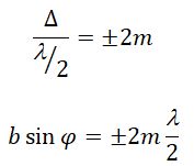
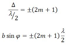
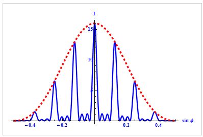
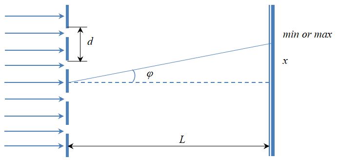


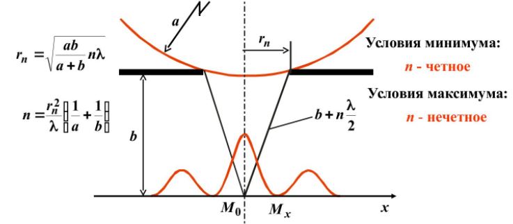


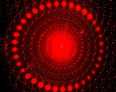
![Colors seen in a spider web are partially due to diffraction, according to some analyses.[16]](https://upload.wikimedia.org/wikipedia/commons/thumb/2/26/Diffraction_pattern_in_spiderweb.JPG/270px-Diffraction_pattern_in_spiderweb.JPG)


![{displaystyle I(theta )=I_{0},operatorname {sinc} ^{2}left[{frac {dpi }{lambda }}(sin theta pm sin theta _{i})right]}](https://wikimedia.org/api/rest_v1/media/math/render/svg/71bd3665f2b7d4923ef1b73aa29087bf566ff80f)


