Протокол TCP/IP или как работает Интернет для чайников:
В основе работы глобальной сети Интернет лежит набор (стек) протоколов TCP/IP — это простой набор хорошо известных правил обмена информацией.
Вам приходилось наблюдать панику и полную беспомощность бухгалтера при смене версии офисного софта — при малейшем изменении последовательности кликов мышки, требуемых для выполнения привычных действий? Или приходилось видеть человека, впадающего в ступор при изменении интерфейса рабочего стола? Вот для того, чтобы не быть лохом необходимо понимание сути. Основе информации дают вам возможность чувствовать себя уверенно и свободно — быстро решать проблемы, грамотно формулировать вопросы и нормально общаться с техподдержкой.
Принципы работы интернет-протоколов TCP/IP по своей сути просты и напоминают работу советской почты:
Сначала вы пишете письмо, затем кладете его в конверт, заклеиваете, на обратной стороне конверта пишете адреса отправителя и получателя, а потом относите в ближайшее почтовое отделение. Далее письмо проходит через цепочку почтовых отделений до ближайшего почтового отделения получателя, откуда оно тетей-почтальоном доставляется до по указанному адресу получателя и опускается в его почтовый ящик (с номером его квартиры) или вручается лично. Когда получатель письма захочет вам ответить, то он в своем ответном письме поменяет местами адреса получателя и отправителя, и письмо отправиться к вам по той же цепочке, но в обратном направлении.
Адрес отправителя:
От кого: Иванов Иван Иванович
Откуда: Ивантеевка, ул. Большая , д. 8, кв. 25

Адрес получателя:
Кому: Петров Петр Петрович
Куда: Москва, Усачевский переулок, д. 105, кв. 110
Рассмотрим взаимодействие компьютеров и приложений в сети Интернет, да и в локальной сети тоже. Аналогия с обычной почтой будет почти полной.
Каждый компьютер (он же: узел, хост) в рамках сети Интернет тоже имеет уникальный адрес, который называется IP (Internet Pointer), например: 195.34.32.116. IP адрес состоит из четырех десятичных чисел (от 0 до 255), разделенных точкой. Но знать только IP адрес компьютера еще недостаточно, т.к. в конечном счете обмениваются информацией не компьютеры сами по себе, а приложения, работающие на них. А на компьютере может одновременно работать сразу несколько приложений (например почтовый сервер, веб-сервер и пр.). Для доставки обычного бумажного письма недостаточно знать только адрес дома — необходимо еще знать номер квартиры. Также и каждое программное приложение имеет подобный номер, именуемый номером порта. Большинство серверных приложений имеют стандартные номера, например: почтовый сервис привязан к порту с номером 25 (еще говорят: «слушает» порт, принимает на него сообщения), веб-сервис привязан к порту 80, FTP — к порту 21 и так далее. Таким образом имеем следующую практически полную аналогию с нашим обычным почтовым адресом: «адрес дома» = «IP компьютера», а «номер квартиры» = «номер порта»
Адрес отправителя (Source address):
IP: 82.146.49.55
Port: 2049
Адрес получателя (Destination address):
IP: 195.34.32.116
Port: 53
Данные пакета:
…
Конечно же в пакетах также присутствует служебная информация, но для понимания сути это не важно.
Комбинация «IP адрес и номер порта» — называется «сокет».
В нашем примере мы с сокета 82.146.49.55:2049 посылаем пакет на сокет 195.34.32.116:53, т.е. пакет пойдет на компьютер, имеющий IP адрес 195.34.32.116, на порт 53. А порту 53 соответствует сервер распознавания имен (DNS-сервер), который примет этот пакет. Зная адрес отправителя, этот сервер сможет после обработки нашего запроса сформировать ответный пакет, который пойдет в обратном направлении на сокет отправителя 82.146.49.55:2049, который для DNS сервера будет являться сокетом получателя.
Как правило взаимодействие осуществляется по схеме «клиент-сервер»: «клиент» запрашивает какую-либо информацию (например страницу сайта), сервер принимает запрос, обрабатывает его и посылает результат. Номера портов серверных приложений общеизвестны, например: почтовый SMTP сервер «слушает» 25-й порт, POP3 сервер, обеспечивающий чтение почты из ваших почтовых ящиков «слушает» 110-порт, веб-сервер — 80-й порт и пр. Большинство программ на домашнем компьютере являются клиентами — например почтовый клиент Outlook, веб-обозреватели IE, FireFox и пр. Номера портов на клиенте не фиксированные как у сервера, а назначаются операционной системой динамически. Фиксированные серверные порты как правило имеют номера до 1024 (но есть исключения), а клиентские начинаются после 1024.
IP — это адрес компьютера (узла, хоста) в сети, а порт — номер конкретного приложения, работающего на этом компьютере. Однако человеку запоминать цифровые IP адреса трудно — куда удобнее работать с буквенными именами. Ведь намного легче запомнить слово, чем набор цифр. Так и сделано — любой цифровой IP адрес можно связать с буквенно-цифровым именем. В результате например вместо 82.146.49.55 можно использовать имя www.ofnet.ru. А преобразованием доменного имени в цифровой IP адрес занимается сервис доменных имен — DNS (Domain Name System).
Набираем в адресной строке браузера доменное имя www.yandex.ru и жмем
. Далее операционная система производит следующие действия:
— Отправляется запрос (точнее пакет с запросом) DNS серверу на сокет 195.34.32.116:53.
Порт 53 соответствует DNS-серверу — приложению, занимающемуся распознаванием имен. А DNS-сервер, обработав наш запрос, возвращает IP-адрес, который соответствует введенному имени. Диалог следующий: Какой IP адрес соответствует имени www.yandex.ru? Ответ: 82.146.49.55.
— Далее наш компьютер устанавливает соединение с портом 80 компьютера 82.146.49.55 и посылает запрос (пакет с запросом) на получение страницы www.yandex.ru. 80-й порт соответствует веб-серверу. В адресной строке браузера 80-й порт не пишется, т.к. используется по умолчанию, но его можно и явно указать после двоеточия — http://www.yandex.ru:80.
— Приняв от нас запрос, веб-сервер обрабатывает его и в нескольких пакетах посылает нам страницу в на языке HTML — языке разметки текста, который понимает браузер. Наш браузер, получив страницу, отображает ее. В результате мы видим на экране главную страницу этого сайта.
Зачем мне это знать?
Например, вы заметили странное поведение своего компьютера — непонятная сетевая активность, тормоза и пр. Что делать? Открываем консоль (нажимаем кнопку «Пуск» — «Выполнить» — набираем cmd — «Ок»). В консоли набираем команду netstat -an и жмем
. Эта утилита отобразит список установленных соединений между сокетами нашего компьютера и сокетами удаленных узлов.
Если мы видим в колонке «Внешний адрес» какие-то чужие IP адреса, а через двоеточие 25-й порт, что это может означать? (Помните, что 25-й порт соответствует почтовому серверу?) Это означает то, что ваш компьютер установил соединение с каким-то почтовым сервером (серверами) и шлет через него какие-то письма. И если ваш почтовый клиент (Outlook например) в это время не запущен, да если еще таких соединений на 25-й порт много, то, вероятно, в вашем компьютере завелся вирус, который рассылает от вашего имени спам или пересылает номера ваших кредитных карточек вкупе с паролями злоумышленникам.
Также понимание принципов работы Интернета необходимо для правильной настройки файерволла (брандмауэра) — программа (часто поставляется вместе с антивирусом), предназначенна для фильтрации пакетов «своих» и «вражеских». Например, ваш фаерволл сообщает, что некто хочет установить соединение с каким-либо портом вашего компьютера. Разрешить или запретить?
Все эти знания крайне полезны при общении с техподдержкой — список портов, с которыми вам придется столкнуться:
135-139 — эти порты используются Windows для доступа к общим ресурсам компьютера — папкам, принтерам. Не открывайте эти порты наружу, т.е. в районную локальную сеть и Интернет. Их следует закрыть фаерволлом. Также если в локальной сети вы не видите ничего в сетевом окружении или вас не видят, то вероятно это связано с тем, что фаерволл заблокировал эти порты. Таким образом для локальной сети эти порты должны быть открыты, а для Интернета закрыты.
21 — порт FTP сервера.
25 — порт почтового SMTP сервера. Через него ваш почтовый клиент отправляет письма. IP адрес SMTP сервера и его порт (25-й) следует указать в настройках вашего почтового клиента.
110 — порт POP3 сервера. Через него ваш почтовый клиент забирает письма из вашего почтового ящика. IP адрес POP3 сервера и его порт (110-й) также следует указать в настройках вашего почтового клиента.
80 — порт WEB-сервера.
3128, 8080 — прокси-серверы (настраиваются в параметрах браузера).
Несколько специальных IP адресов:
127.0.0.1 — это localhost, адрес локальной системы, т.е. локальный адрес вашего компьютера.
0.0.0.0 — так обозначаются все IP-адреса.
192.168.xxx.xxx — адреса, которые можно произвольно использовать в локальных сетях, в глобальной сети Интернет они не используются. Они уникальны только в рамках локальной сети. Адреса из этого диапазона вы можете использовать по своему усмотрению, например, для построения домашней или офисной сети.
Что такое маска подсети и шлюз по умолчанию, он же роутер и маршрутизатор? Эти параметры задаются в настройках сетевых подключений. Компьютеры объединяются в локальные сети. В локальной сети компьютеры напрямую «видят» только друг друга. Локальные сети соединяются друг с другом через шлюзы (роутеры, маршрутизаторы). Маска подсети предназначена для определения — принадлежит ли компьютер-получатель к этой же локальной сети или нет. Если компьютер-получатель принадлежит этой же сети, что и компьютер-отправитель, то пакет передается ему напрямую, в противном случае пакет отправляется на шлюз по умолчанию, который далее, по известным ему маршрутам, передает пакет в другую сеть, т.е. в другое почтовое отделение (по аналогии с бумажной почтой). Итак:
TCP/IP — это название набора сетевых протоколов. На самом деле передаваемый пакет проходит несколько уровней. (Как на почте: сначала вы пишете писмо, потом помещаете в конверт с адресом, затем на почте на нем ставится штамп и т.д.).
IP протокол — это протокол так называемого сетевого уровня. Задача этого уровня — доставка ip-пакетов от компьютера отправителя к компьютеру получателю. Помимо собственно данных, пакеты этого уровня имеют ip-адрес отправителя и ip-адрес получателя. Номера портов на сетевом уровне не используются. Какому порту=приложению адресован этот пакет, был ли этот пакет доставлен или был потерян, на этом уровне неизвестно — это не его задача, это задача транспортного уровня.
TCP и UDP — это протоколы так называемого транспортного уровня. Транспортный уровень находится над сетевым. На этом уровне к пакету добавляется порт отправителя и порт получателя.
TCP — это протокол с установлением соединения и с гарантированной доставкой пакетов. Сначала производится обмен специальными пакетами для установления соединения, происходит что-то вроде рукопожатия (-Привет. -Привет. -Поболтаем? -Давай.). Далее по этому соединению туда и обратно посылаются пакеты (идет беседа), причем с проверкой, дошел ли пакет до получателя. Если пакет не дошел, то он посылается повторно («повтори, не расслышал»).
UDP — это протокол без установления соединения и с негарантированной доставкой пакетов. (Типа: крикнул что-нибудь, а услышат тебя или нет — неважно).
Над транспортным уровнем находится прикладной уровень. На этом уровне работают такие протоколы, как http, ftp и пр. Например HTTP и FTP — используют надежный протокол TCP, а DNS-сервер работает через ненадежный протокол UDP.
Как посмотреть текущие соединения? — с помощью команды netstat -an (параметр n указывает выводить IP адреса вместо доменных имен). Запускается эта команда следующим образом: «Пуск» — «Выполнить» — набираем cmd — «Ок». В появившейся консоли (черное окно) набираем команду netstat -an и жмем
. Результатом будет список установленных соединений между сокетами нашего компьютера и удаленных узлов. Например получаем:
В этом примере 0.0.0.0:135 — означает, что наш компьютер на всех своих IP адресах слушает (LISTENING) 135-й порт и готов принимать на него соединения от кого угодно (0.0.0.0:0) по протоколу TCP.
91.76.65.216:139 — наш компьютер слушает 139-й порт на своем IP-адресе 91.76.65.216.
Третья строка означает, что сейчас установлено (ESTABLISHED) соединение между нашей машиной (91.76.65.216:1719) и удаленной (212.58.226.20:80). Порт 80 означает, что наша машина обратилась с запросом к веб-серверу (у меня, действительно, открыты страницы в браузере).

(с) Вольные сокращения статьи мои.
(с) Дубровин Борис полный оригинал статьи
Cтек протоколов TCP/IP широко распространен. Он используется в качестве основы для глобальной сети интернет. Разбираемся в основных понятиях и принципах работы стека.
Стек протоколов TCP/IP (Transmission Control Protocol/Internet Protocol, протокол управления передачей/протокол интернета) — сетевая модель, описывающая процесс передачи цифровых данных. Она названа по двум главным протоколам, по этой модели построена глобальная сеть интернет. Сейчас это кажется невероятным, но в 1970-х информация не могла быть передана из одной сети в другую. Чтобы обеспечить такую возможность, был разработан стек интернет-протоколов, известный как TCP/IP.
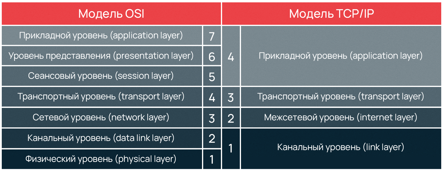
Разработка сетевой модели осуществлялась при содействии Министерства обороны США, поэтому иногда модель TCP/IP называют DoD (Department of Defence) модель. Если вы знакомы с моделью OSI, то вам будет проще понять построение модели TCP/IP, потому что обе модели имеют деление на уровни, внутри которых действуют определенные протоколы и выполняются собственные функции. Мы разделили статью на смысловые части, чтобы было проще понять, как устроена модель TCP/IP:
Уровневая модель TCP/IP
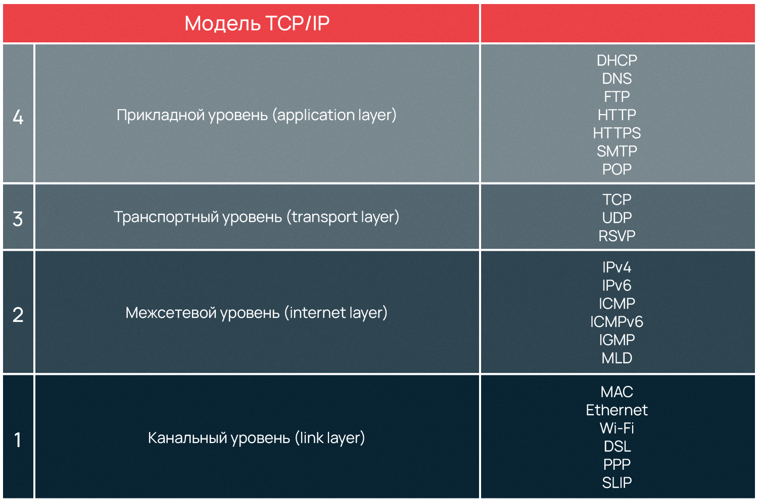
Выше мы уже упоминали, что модель TCP/IP разделена на уровни, как и OSI, но отличие двух моделей в количестве уровней. Документами, определяющими сертификацию модели, являются RFC 1122 и RFC1123. Эти стандарты описывают четыре уровня абстракции модели TCP/IP: прикладной, транспортный, межсетевой и канальный. Существуют и другие версии описания модели, в том числе включающие иное количество уровней и их наименований. Однако в этой статье мы придерживаемся оригинальной версии и далее рассмотрим четыре уровня модели.
Канальный уровень (link layer)
Предназначение канального уровня — дать описание тому, как происходит обмен информацией на уровне сетевых устройств, определить, как информация будет передаваться от одного устройства к другому. Информация здесь кодируется, делится на пакеты и отправляется по нужному каналу, т.е. среде передачи.
Этот уровень также вычисляет максимальное расстояние, на которое пакеты возможно передать, частоту сигнала, задержку ответа и т.д. Все это — физические свойства среды передачи информации. На канальном уровне самым распространенным протоколом является Ethernet, который мы рассмотрим в конце статьи.
Межсетевой уровень (internet layer)
Глобальная сеть интернет состоит из множества локальных сетей, взаимодействующих между собой. Межсетевой уровень используется, чтобы описать обеспечение такого взаимодействия.
Межсетевое взаимодействие — это основной принцип построения интернета. Локальные сети по всему миру объединены в глобальную, а передачу данных между этими сетями осуществляют магистральные и пограничные маршрутизаторы.
Именно на межсетевом уровне функционирует протокол IP, позволивший объединить разные сети в глобальную. Как и протокол TCP, он дал название модели, рассматриваемой в статье.
Маска подсети и IP-адреса
Маска подсети помогает маршрутизатору понять, как и куда передавать пакет. Подсетью может являться любая сеть со своими протоколами. Маршрутизатор передает пакет напрямую, если получатель находится в той же подсети, что и отправитель. Если же подсети получателя и отправителя различаются, пакет передается на второй маршрутизатор, со второго на третий и далее по цепочке, пока не достигнет получателя.
Протокол IP (Internet Protocol) используется маршрутизатором, чтобы определить, к какой подсети принадлежит получатель. Свой уникальный IP-адрес есть у каждого сетевого устройства, при этом в глобальной сети не может существовать два устройства с одинаковым IP. Протокол имеет две действующие версии, первая из которых — IPv4 (IP version 4, версии 4) — была описана в 1981 году.
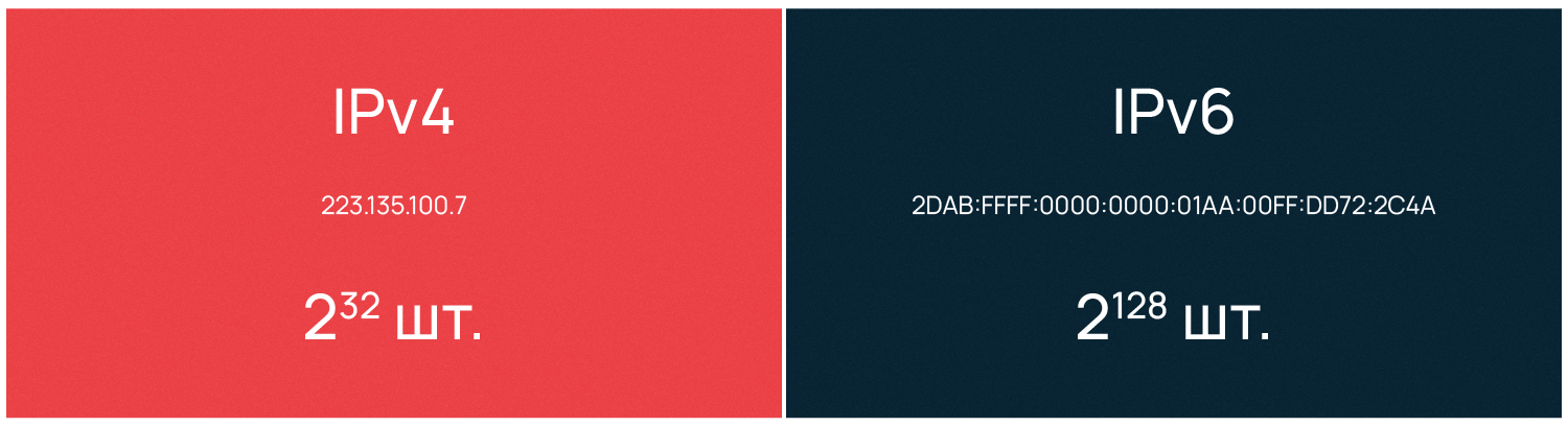
IPv4 предусматривает назначение каждому устройству 32-битного IP-адреса, что ограничивало максимально возможное число уникальных адресов 4 миллиардами (2^32). В более привычном для человека десятичном виде IPv4 выглядит как четыре блока (октета) чисел от 0 до 255, разделенных тремя точками. Первый октет IP-адреса означает класс сети, классов всего 5: A, B, C, D, E. Gри этом адреса сети D являются мультикастовыми, а сети E вообще не используются.
Рассмотрим, например, IPv4 адрес класса С 223.135.100.7. Первые три октета определяют класс и номер сети, а последний означает номер конечного устройства. Например, если необходимо отправить информацию с компьютера номер 7 с IPv4 адресом 223.135.100.7 на компьютер номер 10 в той же подсети, то адрес компьютера получателя будет следующий: 223.135.100.10.
В связи с быстрым ростом сети интернет остро вставала необходимость увеличения числа возможных IP-адресов. В 1995 году впервые был описан протокол IPv6 (IP version 6, версии 6), который использует 128-битные адреса и позволяет назначить уникальные адреса для 2^128 устройств.
IPv6 имеет вид восьми блоков по четыре шестнадцатеричных значения, а каждый блок разделяется двоеточием. IPv6 выглядит следующим образом:
2dab:ffff:0000:0000:01aa:00ff:dd72:2c4a.
Так как IPv6 адреса длинные, их разрешается сокращать по определенным правилам, которые также описываются RFC:
- Для написания адреса используются строчные буквы латинского алфавита: a, b, c, d, e, f.
- Ведущие нули допускается не указывать — например, в адресе выше :00ff: можно записать как :ff:.
- Группы нулей, идущие подряд, тоже допустимо сокращать и заменять на двойное двоеточие. На примере выше это выглядит так: 2dab:аааа::01aa:00ff:dd72:2c4a. Допускается делать не больше одного подобного сокращения в адресе IPv6 на наибольшей последовательности нулей. Если одинаково длинных последовательностей несколько — на самой левой из них.
IP предназначен для определения адресата и доставки ему информации. Он предоставляет услугу для вышестоящих уровней, но не гарантирует целостность доставляемой информации.
IP способен инкапсулировать другие протоколы, предоставлять место, куда они могут быть встроены. К таким протоколам, например, относятся ICMP (межсетевой протокол управляющих сообщений) и IGMP (межсетевой протокол группового управления). Информация о том, какой протокол инкапсулируется, отражается в заголовке IP-пакета. Так, ICMP будет обозначен числом 1, а IGMP будет обозначен числом 2.
ICMP
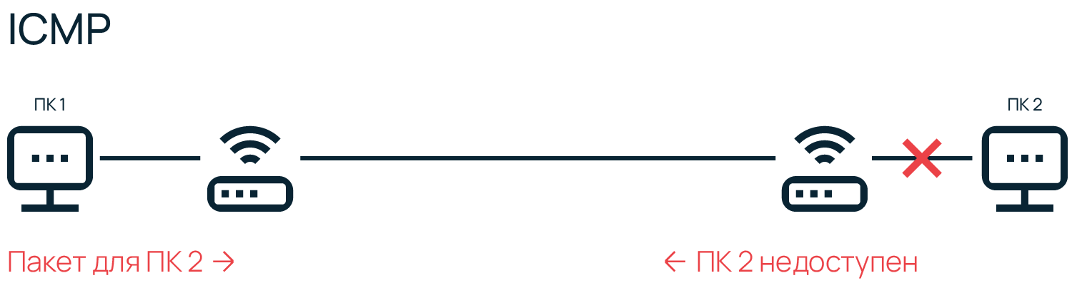
ICMP в основном используется устройствами в сети для доставки сообщений об ошибках и операционной информации, сообщающей об успехе или ошибке при связи с другим устройством. Например, именно с использованием ICMP осуществляется передача отчетов о недоступности устройств в сети. Кроме того, ICMP используется при диагностике сети — к примеру, в эксплуатации утилит ping или traceroute.
ICMP не передает какие-либо данные, что отличает его от протоколов, работающих на транспортном уровне — таких как TCP и UDP. ICMP, аналогично IP, работает на межсетевом уровне и фактически является неотъемлемой частью при реализации модели TCP/IP. Стоит отметить, что для разных версий IP используются и разные версии протокола ICMP.
Транспортный уровень (transport layer)
Постоянные резиденты транспортного уровня — протоколы TCP и UDP, они занимаются доставкой информации.
TCP (протокол управления передачей) — надежный, он обеспечивает передачу информации, проверяя дошла ли она, насколько полным является объем полученной информации и т.д. TCP дает возможность двум конечным устройствам производить обмен пакетами через предварительно установленное соединение. Он предоставляет услугу для приложений, повторно запрашивает потерянную информацию, устраняет дублирующие пакеты, регулируя загруженность сети. TCP гарантирует получение и сборку информации у адресата в правильном порядке.
UDP (протокол пользовательских датаграмм) — ненадежный, он занимается передачей автономных датаграмм. UDP не гарантирует, что всех датаграммы дойдут до получателя. Датаграммы уже содержат всю необходимую информацию, чтобы дойти до получателя, но они все равно могут быть потеряны или доставлены в порядке отличном от порядка при отправлении.
UDP обычно не используется, если требуется надежная передача информации. Использовать UDP имеет смысл там, где потеря части информации не будет критичной для приложения, например, в видеоиграх или потоковой передаче видео. UDP необходим, когда делать повторный запрос сложно или неоправданно по каким-то причинам.
Протоколы транспортного уровня не интерпретируют информацию, полученную с верхнего или нижних уровней, они служат только как канал передачи, но есть исключения. RSVP (Resource Reservation Protocol, протокол резервирования сетевых ресурсов) может использоваться, например, роутерами или сетевыми экранами в целях анализа трафика и принятия решений о его передаче или отклонении в зависимости от содержимого.
Прикладной уровень (application layer)
В модели TCP/IP отсутствуют дополнительные промежуточные уровни (представления и сеансовый) в отличие от OSI. Функции форматирования и представления данных делегированы библиотекам и программным интерфейсам приложений (API) — своего рода базам знаний, содержащим сведения о том, как приложения взаимодействуют между собой. Когда службы или приложения обращаются к библиотеке или API, те в ответ предоставляют набор действий, необходимых для выполнения задачи и полную инструкцию, каким образом эти действия нужно выполнять.
Протоколы прикладного уровня действуют для большинства приложений, они предоставляют услуги пользователю или обмениваются данными с «коллегами» с нижних уровней по уже установленным соединениям. Здесь для большинства приложений созданы свои протоколы. Например, браузеры используют HTTP для передачи гипертекста по сети, почтовые клиенты — SMTP для передачи почты, FTP-клиенты — протокол FTP для передачи файлов, службы DHCP — протокол назначения IP-адресов DHCP и так далее.
Сети в Selectel
Узнайте, как устроена сетевая архитектура крупного провайдера.
Узнать
Зачем нужен порт и что означает термин «сокет»
Приложения прикладного уровня, общаются также с предыдущим, транспортным, но они видят его протоколы как «черные ящики». Для приема-передачи информации они могут работать, например, с TCP или UDP, но понимают только конечный адрес в виде IP и порта, а не принцип их работы.
Как говорилось ранее, IP-адрес присваивается каждому конечному устройству протоколом межсетевого уровня. Но обмен данными происходит не между конечными устройствами, а между приложениями, установленными на них. Чтобы получить доступ к тому или иному сетевому приложению недостаточно только IP-адреса, поэтому для идентификации приложений применяют также порты. Комбинация IP-адреса и порта называется сокетом, или гнездом (socket).
Кроме собственных протоколов, приложения на прикладном уровне зачастую имеют и фиксированный номер порта для обращения к сети. Администрация адресного пространства интернет (IANA), занимающаяся выделением диапазонов IP-адресов, отвечает еще за назначение сетевым приложениям портов.
Так почтовые приложения, которые общаются по SMTP-протоколу, используют порт 25, по протоколу POP3 — порт 110, браузеры при работе по HTTP — порт 80, FTP-клиенты — порт 21. Порт всегда записывается после IP и отделяется от него двоеточием, выглядит это, например, так: 192.168.1.1:80.
Что такое DNS и для чего используется эта служба
Чтобы не запоминать числовые адреса интернет-серверов была создана DNS — служба доменных имен. DNS всегда слушает на 53 порту и преобразует буквенные имена сетевых доменов в числовые IP-адреса и наоборот. Служба DNS позволяет не запоминать IP — компьютер самостоятельно посылает запрос «какой IP у selectel.ru?» на 53 порт DNS-сервера, полученного от поставщика услуг интернет.
DNS-сервер дает компьютеру ответ «IP для selectel.ru — XXX.XXX.XXX.XXX». Затем, компьютер устанавливает соединение с веб-сервером полученного IP, который слушает на порту 80 для HTTP-протокола и на порту 443 для HTTPS. В браузере порт не отображается в адресной строке, а используется по умолчанию, но, по сути, полный адрес сайта Selectel выглядит вот так: https://selectel.ru:443.
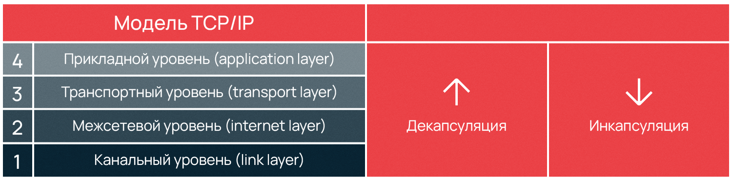
Для обеспечения корректной работы протоколов различных уровней в сетевых моделях используется специальный метод — инкапсуляция. Суть этого метода заключается в добавлении заголовка протокола текущего уровня к данным, полученным от протокола вышестоящего уровня. Процесс, обратный описанному, называется декапсуляцией. Оба процесса осуществляются на компьютерах получателя и отправителя данных попеременно, это позволяет долго не удерживать одну сторону канала занятой, оставляя время на передачу информации другому компьютеру.
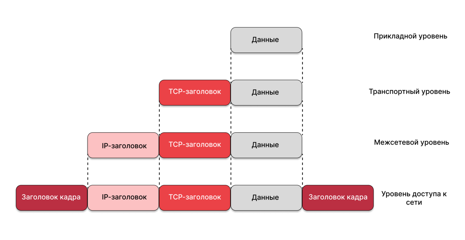
Стек протоколов, снова канальный уровень
О канальном уровне модели TCP/IP мы рассказали меньше всего. Давайте вернемся еще раз к началу, чтобы рассмотреть инкапсуляцию протоколов и что значит «стек».
Большинству пользователей знаком протокол Ethernet. В сети, по стандарту Ethernet, устройства отправителя и адресата имеют определенный MAC-адрес — идентификатор «железа». MAC-адрес инкапсулируется в Ethernet вместе с типом передаваемых данных и самими данными. Фрагмент данных, составленных в соответствии с Ethernet, называется фреймом, или кадром (frame).
MAC-адрес каждого устройства уникален, и двух «железок» с одинаковым адресом не должно существовать. Совпадение может привести к сетевым проблемам. Таким образом, при получении кадра сетевой адаптер занимается извлечением полученной информации и ее дальнейшей обработкой.
После ознакомления с уровневой структурой модели становится понятно, что информация не может передаваться между двумя компьютерами напрямую. Сначала кадры передаются на межсетевой уровень, где компьютеру отправителя и компьютеру получателя назначается уникальный IP. После чего, на транспортном уровне, информация передается в виде TCP-фреймов либо UDP-датаграмм.
На каждом этапе, подобно снежному кому, к уже имеющейся информации добавляется служебная информация, например, порт на прикладном уровне, необходимый для идентификации сетевого приложения. Добавление служебной информации к основной обеспечивают разные протоколы — сначала Ethernet, поверх него IP, еще выше TCP, над ним порт, означающий приложение с делегированным ему протоколом. Такая вложенность называется стеком, названным TCP/IP по двум главным протоколам модели.
Point-to-Point протоколы
Отдельно расскажем о Point-to-Point (от точки к точке, двухточечный) протоколе, также известном как PPP. PPP уникален по своим функциям, он применяется для коммуникации между двумя маршрутизаторами без участия хоста или какой-либо сетевой структуры в промежутке. При необходимости PPP обеспечивает аутентификацию, шифрование, а также сжатие данных. Он широко используется при построении физических сетей, например, кабельных телефонных, сотовых телефонных, сетей по кабелю последовательной передачи и транк-линий (когда один маршрутизатор подключают к другому для увеличения размера сети).
У PPP есть два подвида — PPPoE (PPP по Ethernet) и PPPoA (PPP через асинхронный способ передачи данных — ATM), интернет-провайдеры часто их используют для DSL соединений.
PPP и его старший аналог SLIP (протокол последовательной межсетевой связи) формально относятся к межсетевому уровню TCP/IP, но в силу особого принципа работы, иногда выделяются в отдельную категорию. Преимущество PPP в том, что для установки соединения не требуется сетевая инфраструктура, а необходимость маршрутизаторов отпадает. Эти факторы обуславливают специфику использования PPP протоколов.
Заключение
Стек TCP/IP регламентирует взаимодействие разных уровней. Ключевым понятием здесь являются протоколы, формирующие стек, встраиваясь друг в друга с целью передать данные. Рассмотренная модель по сравнению с OSI имеет более простую архитектуру.
Сама модель остается неизменной, в то время как стандарты протоколов могут обновляться, что еще дальше упрощает работу с TCP/IP. Благодаря всем преимуществам стек TCP/IP получил широкое распространение и использовался сначала в качестве основы для создания глобальной сети, а после для описания работы интернета.
В основе работы глобальной сети Интернет лежит набор (стек) протоколов TCP/IP. Но эти термины лишь на первый взгляд кажутся сложными. На самом деле стек протоколов TCP/IP — это простой набор правил обмена информацией, и правила эти на самом деле вам хорошо известны, хоть вы, вероятно, об этом и не догадываетесь. Да, все именно так, по существу в принципах, лежащих в основе протоколов TCP/IP, нет ничего нового: все новое — это хорошо забытое старое.
Человек может учиться двумя путями:
- Через тупое формальное зазубривание шаблонных способов решения типовых задач (чему сейчас в основном и учат в школе). Такое обучение малоэффективно. Наверняка вам приходилось наблюдать панику и полную беспомощность бухгалтера при смене версии офисного софта — при малейшем изменении последовательности кликов мышки, требуемых для выполнения привычных действий. Или приходилось видеть человека, впадающего в ступор при изменении интерфейса рабочего стола?
- Через понимание сути проблем, явлений, закономерностей. Через понимание принципов построения той или иной системы. В этом случае обладание энциклопедическими знаниями не играет большой роли — недостающую информацию легко найти. Главное — знать, что искать. А для этого необходимо не формальное знание предмета, а понимание сути.
В этой статье я предлагаю пойти вторым путем, так как понимание принципов, лежащих в основе работы Интернета, даст вам возможность чувствовать себя в Интернете уверенно и свободно — быстро решать возникающие проблемы, грамотно формулировать проблемы и уверенно общаться с техподдержкой.
Итак, начнем.
Принципы работы интернет-протоколов TCP/IP по своей сути очень просты и сильно напоминают работу нашей советской почты.
Вспомните, как работает наша обычная почта. Сначала вы на листке пишете письмо, затем кладете его в конверт, заклеиваете, на обратной стороне конверта пишете адреса отправителя и получателя, а потом относите в ближайшее почтовое отделение. Далее письмо проходит через цепочку почтовых отделений до ближайшего почтового отделения получателя, откуда оно тетей-почтальоном доставляется до по указанному адресу получателя и опускается в его почтовый ящик (с номером его квартиры) или вручается лично. Все, письмо дошло до получателя. Когда получатель письма захочет вам ответить, то он в своем ответном письме поменяет местами адреса получателя и отправителя, и письмо отправиться к вам по той же цепочке, но в обратном направлении.
На конверте письма будет написано примерно следующее:
Адрес отправителя: От кого: Иванов Иван Иванович Откуда: Ивантеевка, ул. Большая , д. 8, кв. 25 Адрес получателя: Кому: Петров Петр Петрович Куда: Москва, Усачевский переулок, д. 105, кв. 110
Теперь мы готовы рассмотреть взаимодействие компьютеров и приложений в сети Интернет (да и в локальной сети тоже). Обратите внимание, что аналогия с обычной почтой будет почти полной.
Каждый компьютер (он же: узел, хост) в рамках сети Интернет тоже имеет уникальный адрес, который называется IP-адрес (Internet Protocol Address), например: 195.34.32.116. IP адрес состоит из четырех десятичных чисел (от 0 до 255), разделенных точкой. Но знать только IP адрес компьютера еще недостаточно, т.к. в конечном счете обмениваются информацией не компьютеры сами по себе, а приложения, работающие на них. А на компьютере может одновременно работать сразу несколько приложений (например почтовый сервер, веб-сервер и пр.). Для доставки обычного бумажного письма недостаточно знать только адрес дома — необходимо еще знать номер квартиры. Также и каждое программное приложение имеет подобный номер, именуемый номером порта. Большинство серверных приложений имеют стандартные номера, например: почтовый сервис привязан к порту с номером 25 (еще говорят: «слушает» порт, принимает на него сообщения), веб-сервис привязан к порту 80, FTP — к порту 21 и так далее.
Таким образом имеем следующую практически полную аналогию с нашим обычным почтовым адресом:
"адрес дома" = "IP компьютера"
"номер квартиры" = "номер порта"
В компьютерных сетях, работающих по протоколам TCP/IP, аналогом бумажного письма в конверте является пакет, который содержит собственно передаваемые данные и адресную информацию — адрес отправителя и адрес получателя, например:
Адрес отправителя (Source address):
IP: 82.146.49.55
Port: 2049

Адрес получателя (Destination address):
IP: 195.34.32.116
Port: 53

Данные пакета:
...
Конечно же в пакетах также присутствует служебная информация, но для понимания сути это не важно.
Обратите внимание, комбинация: «IP адрес и номер порта» — называется «сокет».
В нашем примере мы с сокета 82.146.49.55:2049 посылаем пакет на сокет 195.34.32.116:53, т.е. пакет пойдет на компьютер, имеющий IP адрес 195.34.32.116, на порт 53. А порту 53 соответствует сервер распознавания имен (DNS-сервер), который примет этот пакет. Зная адрес отправителя, этот сервер сможет после обработки нашего запроса сформировать ответный пакет, который пойдет в обратном направлении на сокет отправителя 82.146.49.55:2049, который для DNS сервера будет являться сокетом получателя.
Как правило взаимодействие осуществляется по схеме «клиент-сервер»: «клиент» запрашивает какую-либо информацию (например страницу сайта), сервер принимает запрос, обрабатывает его и посылает результат. Номера портов серверных приложений общеизвестны, например: почтовый SMTP сервер «слушает» 25-й порт, POP3 сервер, обеспечивающий чтение почты из ваших почтовых ящиков «слушает» 110-порт, веб-сервер — 80-й порт и пр.
Большинство программ на домашнем компьютере являются клиентами — например почтовый клиент Outlook, веб-обозреватели IE, FireFox и пр.
Номера портов на клиенте не фиксированные как у сервера, а назначаются операционной системой динамически. Фиксированные серверные порты как правило имеют номера до 1024 (но есть исключения), а клиентские начинаются после 1024.
Повторение — мать учения: IP — это адрес компьютера (узла, хоста) в сети, а порт — номер конкретного приложения, работающего на этом компьютере.
Однако человеку запоминать цифровые IP адреса трудно — куда удобнее работать с буквенными именами. Ведь намного легче запомнить слово, чем набор цифр. Так и сделано — любой цифровой IP адрес можно связать с буквенно-цифровым именем. В результате например вместо 82.146.49.55 можно использовать имя www.ofnet.ru. А преобразованием доменного имени в цифровой IP адрес занимается сервис доменных имен — DNS (Domain Name System).
Рассмотрим подробнее, как это работает. Ваш провайдер явно (на бумажке, для ручной настройки соединения) или неявно (через автоматическую настройку соединения) предоставляет вам IP адрес сервера имен (DNS). На компьютере с этим IP адресом работает приложение (сервер имен), которое знает все доменные имена в Интернете и соответствующие им цифровые IP адреса. DNS-сервер «слушает» 53-й порт, принимает на него запросы и выдает ответы, например:
Запрос от нашего компьютера: "Какой IP адрес соответствует имени www.ofnet.ru?"
Ответ сервера: "82.146.49.55."
Теперь рассмотрим, что происходит, когда в своем браузере вы набираете доменное имя (URL) этого сайта (www.ofnet.ru) и, нажав <enter>, в ответ от веб-сервера получаете страницу этого сайта.
Например:
IP адрес нашего компьютера: 91.76.65.216
Браузер: Internet Explorer (IE),
DNS сервер (стрима): 195.34.32.116 (у вас может быть другой), Страница, которую мы хотим открыть: www.ofnet.ru.
Набираем в адресной строке браузера доменное имя www.ofnet.ru и жмем <enter>. Далее операционная система производит примерно следующие действия:
Отправляется запрос (точнее пакет с запросом) DNS серверу на сокет 195.34.32.116:53. Как было рассмотренно выше, порт 53 соответствует DNS-серверу — приложению, занимающемуся распознаванием имен. А DNS-сервер, обработав наш запрос, возвращает IP-адрес, который соответствует введенному имени.
Диалог примерно следующий:
- Какой IP адрес соответствует имени www.ofnet.ru?
- 82.146.49.55.
Далее наш компьютер устанавливает соединение с портом 80 компьютера 82.146.49.55 и посылает запрос (пакет с запросом) на получение страницы www.ofnet.ru. 80-й порт соответствует веб-серверу. В адресной строке браузера 80-й порт как правило не пишется, т.к. используется по умолчанию, но его можно и явно указать после двоеточия — http://www.ofnet.ru:80.
Приняв от нас запрос, веб-сервер обрабатывает его и в нескольких пакетах посылает нам страницу в на языке HTML — языке разметки текста, который понимает браузер.
Наш браузер, получив страницу, отображает ее. В результате мы видим на экране главную страницу этого сайта.
Зачем эти принципы надо понимать?
Например, вы заметили странное поведение своего компьютера — непонятная сетевая активность, тормоза и пр. Что делать? Открываем консоль (нажимаем кнопку «Пуск» — «Выполнить» — набираем cmd — «Ок»). В консоли набираем команду netstat -anи жмем <Enter>. Эта утилита отобразит список установленных соединений между сокетами нашего компьютера и сокетами удаленных узлов. Если мы видим в колонке «Внешний адрес» какие-то чужие IP адреса, а через двоеточие 25-й порт, что это может означать? (Помните, что 25-й порт соответствует почтовому серверу?) Это означает то, что ваш компьютер установил соединение с каким-то почтовым сервером (серверами) и шлет через него какие-то письма. И если ваш почтовый клиент (Outlook например) в это время не запущен, да если еще таких соединений на 25-й порт много, то, вероятно, в вашем компьютере завелся вирус, который рассылает от вашего имени спам или пересылает номера ваших кредитных карточек вкупе с паролями злоумышленникам.
Также понимание принципов работы Интернета необходимо для правильной настройки файерволла (проще говоря брандмауэра :)). Эта программа (которая часто поставляется вместе с антивирусом), предназначенна для фильтрации пакетов — «своих» и «вражеских». Своих пропускать, чужих не пущать. Например, если ваш фаерволл сообщает вам, что некто хочет установить соединение с каким-либо портом вашего компьютера. Разрешить или запретить?
Ну и самое главное — эти знания крайне полезны при общении с техподдержкой.
Напоследок приведу список портов, с которыми вам, вероятно, придется столкнуться:
135-139 — эти порты используются Windows для доступа к общим ресурсам компьютера — папкам, принтерам. Не открывайте эти порты наружу, т.е. в районную локальную сеть и Интернет. Их следует закрыть фаерволлом. Также если в локальной сети вы не видите ничего в сетевом окружении или вас не видят, то вероятно это связано с тем, что фаерволл заблокировал эти порты. Таким образом для локальной сети эти порты должны быть открыты, а для Интернета закрыты.

21 — порт FTP сервера.

25 — порт почтового SMTP сервера. Через него ваш почтовый клиент отправляет письма. IP адрес SMTP сервера и его порт (25-й) следует указать в настройках вашего почтового клиента.

110 — порт POP3 сервера. Через него ваш почтовый клиент забирает письма из вашего почтового ящика. IP адрес POP3 сервера и его порт (110-й) также следует указать в настройках вашего почтового клиента.

80 — порт WEB-сервера.

3128, 8080 — прокси-серверы (настраиваются в параметрах браузера).
Несколько специальных IP адресов:
127.0.0.1 — это localhost, адрес локальной системы, т.е. локальный адрес вашего компьютера.
0.0.0.0 - так обозначаются все IP-адреса.
192.168.xxx.xxx — адреса, которые можно произвольно использовать в локальных сетях, в глобальной сети Интернет они не используются. Они уникальны только в рамках локальной сети. Адреса из этого диапазона вы можете использовать по своему усмотрению, например, для построения домашней или офисной сети.
Что такое маска подсети и шлюз по умолчанию (роутер, маршрутизатор)?
(Эти параметры задаются в настройках сетевых подключений).
Все просто. Компьютеры объединяются в локальные сети. В локальной сети компьютеры напрямую «видят» только друг друга. Локальные сети соединяются друг с другом через шлюзы (роутеры, маршрутизаторы). Маска подсети предназначена для определения — принадлежит ли компьютер-получатель к этой же локальной сети или нет. Если компьютер-получатель принадлежит этой же сети, что и компьютер-отправитель, то пакет передается ему напрямую, в противном случае пакет отправляется на шлюз по умолчанию, который далее, по известным ему маршрутам, передает пакет в другую сеть, т.е. в другое почтовое отделение (по аналогии с советской почтой).
Напоследок рассмотрим что же означают непонятные термины:
TCP/IP — это название набора сетевых протоколов. На самом деле передаваемый пакет проходит несколько уровней. (Как на почте: сначала вы пишете писмо, потом помещаете в конверт с адресом, затем на почте на нем ставится штамп и т.д.).
IP протокол — это протокол так называемого сетевого уровня. Задача этого уровня — доставка ip-пакетов от компьютера отправителя к компьютеру получателю. По-мимо собственно данных, пакеты этого уровня имеют ip-адрес отправителя и ip-адрес получателя. Номера портов на сетевом уровне не используются. Какому порту, т.е. приложению адресован этот пакет, был ли этот пакет доставлен или был потерян, на этом уровне неизвестно — это не его задача, это задача транспортного уровня.
TCP и UDP — это протоколы так называемого транспортного уровня. Транспортный уровень находится над сетевым. На этом уровне к пакету добавляется порт отправителя и порт получателя.
TCP — это протокол с установлением соединения и с гарантированной доставкой пакетов. Сначала производится обмен специальными пакетами для установления соединения, происходит что-то вроде рукопожатия (-Привет. -Привет. -Поболтаем? -Давай.). Далее по этому соединению туда и обратно посылаются пакеты (идет беседа), причем с проверкой, дошел ли пакет до получателя. Если пакет не дошел, то он посылается повторно («повтори, не расслышал»).
UDP — это протокол без установления соединения и с негарантированной доставкой пакетов. (Типа: крикнул что-нибудь, а услышат тебя или нет — неважно).
Над транспортным уровнем находится прикладной уровень. На этом уровне работают такие протоколы, как http, ftp и пр. Например HTTP и FTP — используют надежный протокол TCP, а DNS-сервер работает через ненадежный протокол UDP.
Как посмотреть текущие соединения?
Текущие соединения можно посмотреть с помощью команды
netstat -an
(параметр n указывает выводить IP адреса вместо доменных имен).
Запускается эта команда следующим образом:
«Пуск» — «Выполнить» — набираем cmd — «Ок». В появившейся консоли (черное окно) набираем команду netstat -an и жмем <Enter>. Результатом будет список установленных соединений между сокетами нашего компьютера и удаленных узлов.
Например получаем:
Активные подключения
| Имя | Локальный адрес | Внешний адрес | Состояние |
| TCP | 0.0.0.0:135 | 0.0.0.0:0 | LISTENING |
| TCP | 91.76.65.216:139 | 0.0.0.0:0 | LISTENING |
| TCP | 91.76.65.216:1719 | 212.58.226.20:80 | ESTABLISHED |
| TCP | 91.76.65.216:1720 | 212.58.226.20:80 | ESTABLISHED |
| TCP | 91.76.65.216:1723 | 212.58.227.138:80 | CLOSE_WAIT |
| TCP | 91.76.65.216:1724 | 212.58.226.8:80 | ESTABLISHED |
...
В этом примере 0.0.0.0:135 — означает, что наш компьютер на всех своих IP адресах слушает (LISTENING) 135-й порт и готов принимать на него соединения от кого угодно (0.0.0.0:0) по протоколу TCP.
91.76.65.216:139 — наш компьютер слушает 139-й порт на своем IP-адресе 91.76.65.216.
Третья строка означает, что сейчас установлено (ESTABLISHED) соединение между нашей машиной (91.76.65.216:1719) и удаленной (212.58.226.20:80). Порт 80 означает, что наша машина обратилась с запросом к веб-серверу (у меня, действительно, открыты страницы в браузере).
В следующих статьях мы рассмотрим, как применять эти знания, например общаясь с техподдержкой.
Начальные сведения о портах TCP/IP
Протокол TCP/IP представляет собой фундамент Internet, с помощью которого компьютеры отправляют и принимают информацию из любой точки земного шара, независимо от географического положения. Обратиться к компьютеру с TCP/IP в другой стране так же просто, как к компьютеру, который находится в соседней комнате. Процедура доступа в обоих случаях идентична, хотя для соединения с машиной в другой стране может потребоваться на несколько миллисекунд больше. В результате граждане любой страны могут без труда делать покупки в Amazon.com; однако из-за логической близости усложняется задача информационной защиты: любой владелец подключенного к Internet компьютера в любой точке мира может попытаться установить несанкционированное соединение с любой другой машиной.
Обязанность ИТ-специалистов — установить брандмауэры и системы обнаружения подозрительного трафика. В ходе анализа пакетов извлекается информация об IP-адресах отправителя и назначения и задействованных сетевых портах. Значение сетевых портов не уступает IP-адресам; это важнейшие критерии для отделения полезного трафика от фальшивых и вредных посылок, поступающих в сеть и исходящих из нее. Основная часть сетевого трафика Internet состоит из пакетов TCP и UDP, которые содержат информацию о сетевых портах, используемых компьютерами для того, чтобы направлять трафик от одного приложения в другое. Необходимое условие безопасности брандмауэра и сети — исчерпывающее понимание администратором принципов использования этих портов компьютерами и сетевыми устройствами.
Изучаем порты
Знание основных принципов работы сетевых портов пригодится любому системному администратору. Имея базовые знания об устройстве портов TCP и UDP, администратор может самостоятельно выполнить диагностику отказавшего сетевого приложения или защитить компьютер, которому предстоит обратиться в Internet, не вызывая сетевого инженера или консультанта по брандмауэрам.
В первой части данной статьи (состоящей из двух частей) дается описание основных понятий, необходимых для рассмотрения сетевых портов. Будет показано место сетевых портов в общей сетевой модели и роль сетевых портов и NAT (Network Address Translation — трансляция сетевых адресов) брандмауэра в соединениях компьютеров компании с Internet. И наконец, будут указаны точки сети, в которых удобно идентифицировать и фильтровать сетевой трафик по соответствующим сетевым портам. Во второй части рассматриваются некоторые порты, используемые широко распространенными приложениями и операционными системами, и рассказывается о некоторых инструментах для поиска открытых портов сети.
Краткий обзор сетевых протоколов
TCP/IP — набор сетевых протоколов, через которые компьютеры устанавливают связь друг с другом. Набор TCP/IP — не более чем фрагменты программного кода, установленные в операционной системе и открывающие доступ к этим протоколам. TCP/IP является стандартом, поэтому приложения TCP/IP на компьютере Windows должны успешно обмениваться данными с аналогичным приложением на машине UNIX. В начальный период развития сетей, в 1983 г., инженеры разработали семиуровневую модель взаимодействия OSI для описания процессов сетевого обмена компьютеров, от кабеля до приложения. Модель OSI состоит из физического, канального, сетевого, транспортного, сеансового представления данных и прикладного уровней. Администраторы, постоянно работающие с Internet и TCP/IP, в основном имеют дело с сетевым, транспортным и прикладным уровнями, но для успешной диагностики необходимо знать и другие уровни. Несмотря на солидный возраст модели OSI, ею по-прежнему пользуются многие специалисты. Например, когда сетевой инженер говорит о коммутаторах уровней 1 или 2, а поставщик брандмауэров — о контроле на уровне 7, они имеют в виду уровни, определенные в модели OSI.
В данной статье рассказывается о сетевых портах, расположенных на уровне 4 — транспортном. В наборе TCP/IP эти порты используются протоколами TCP и UDP. Но прежде чем перейти к подробному описанию одного уровня, необходимо кратко ознакомиться с семью уровнями OSI и той ролью, которую они выполняют в современных сетях TCP/IP.
Уровни 1 и 2: физические кабели и адреса MAC
Уровень 1, физический, представляет собственно среду, в которой распространяется сигнал, — например, медный кабель, волоконно-оптический кабель или радиосигналы (в случае Wi-Fi). Уровень 2, канальный, описывает формат данных для передачи в физической среде. На уровне 2 пакеты организуются в кадры и могут быть реализованы базовые функции управления потоком данных и обработки ошибок. Стандарт IEEE 802.3, более известный как Ethernet,— самый распространенный стандарт уровня 2 для современных локальных сетей. Обычный сетевой коммутатор — устройство уровня 2, с помощью которого несколько компьютеров физически подключаются и обмениваются данными друг с другом. Иногда два компьютера не могут установить соединение друг с другом, хотя IP-адреса кажутся корректными: причиной неполадки могут быть ошибки в кэше протокола преобразования адресов ARP (Address Resolution Protocol), что свидетельствует о неисправности на уровне 2. Кроме того, некоторые беспроводные точки доступа (Access Point, AP) обеспечивают фильтрацию адресов MAC, разрешающую соединение с беспроводной AP только сетевым адаптерам с конкретным MAC-адресом.
Уровни 3 и 4: IP-адреса и сетевые порты
Уровень 3, сетевой, поддерживает маршрутизацию. В TCP/IP маршрутизация реализована в IP. IP-адрес пакета принадлежат уровню 3. Сетевые маршрутизаторы — устройства уровня 3, которые анализируют IP-адреса пакетов и пересылают пакеты другому маршрутизатору или доставляют пакеты в локальные компьютеры. Если в сети обнаружен подозрительный пакет, то в первую очередь следует проверить IP-адрес пакета, чтобы установить место происхождения пакета.
Вместе с сетевым уровнем 4-й уровень (транспортный) — хорошая отправная точка для диагностики сетевых неисправностей. В Internet уровень 4 содержит протоколы TCP и UDP и информацию о сетевом порте, который связывает пакет с конкретным приложением. Сетевой стек компьютера использует связь сетевого порта TCP или UDP с приложением, чтобы направить сетевой трафик в это приложение. Например, TCP-порт 80 связан с приложением Web-сервера. Такое соответствие портов с приложениями известно как служба.
TCP и UDP различаются. В сущности, TCP обеспечивает надежное соединение для обмена данными между двумя приложениями. Прежде чем начать обмен данными, два приложения должны установить связь, выполнив трехшаговый процесс установления сязи TCP. Для протокола UDP в большей степени характерен подход «активизировать и забыть». Надежность связи для приложений TCP обеспечивается протоколом, а приложению UDP приходится самостоятельно проверять надежность соединения.
Сетевой порт представляет собой число от 1 до 65535, указанное и известное обоим приложениям, между которыми устанавливается связь. Например, клиент, как правило, посылает незашифрованный запрос в сервер по целевому адресу на TCP-порт 80. Обычно компьютер посылает запрос DNS на DNS-сервер по целевому адресу на UDP-порт 53. Клиент и сервер имеют IP-адрес источника и назначения, а также сетевой порт источника и назначения, которые могут различаться. Исторически все номера портов ниже 1024 получили название «известных номеров портов» и зарегистрированы в организации IANA (Internet Assigned Numbers Authority). В некоторых операционных системах только системные процессы могут использовать порты этого диапазона. Кроме того, организации могут зарегистрировать в IANA порты с 1024 по 49151-й, чтобы связать порт со своим приложением. Такая регистрация обеспечивает структуру, которая помогает избежать конфликтов между приложениями, стремящимися использовать порт с одним номером. Однако в целом ничто не мешает приложению запросить конкретный порт, если он не занят другой активной программой.
Исторически сложилось так, что сервер может прослушивать порты с малыми номерами, а клиент — инициировать соединение от порта с большим номером (выше 1024). Например, Web-клиент может открыть соединение с Web-сервером через порт назначения 80, но ассоциировать произвольно выбранный порт-источник, например TCP-порт 1025. Отвечая клиенту, Web-сервер адресует пакет клиенту с портом-источником 80 и портом назначения 1025. Комбинация IP-адреса и порта называется сокетом (socket), она должна быть уникальной в компьютере. По этой причине при организации Web-сервера с двумя отдельными Web-сайтами на одном компьютере необходимо использовать несколько IP-адресов, например address1:80 и address2:80, или настроить Web-сервер на прослушивание нескольких сетевых портов, таких как address1:80 и address1:81. Некоторые Web-серверы обеспечивают работу нескольких Web-сайтов через один порт, запрашивая хост-заголовок, но в действительности эта функция выполняется приложением Web-сервера на более высоком уровне 7.
По мере того как в операционных системах и приложениях появлялись сетевые функции, программисты начали использовать порты с номерами выше 1024, без регистрации всех приложений в IANA. Выполнив в Internet поиск для любого сетевого порта, как правило, удается быстро найти информацию о приложениях, которые используют этот порт. Или же можно провести поиск по словам Well Known Ports и отыскать множество сайтов со списками наиболее типичных портов.
При блокировании сетевых приложений компьютера или устранении изъянов в брандмауэре основная часть работы приходится на классификацию и фильтрацию IP-адресов уровня 3, а также протоколов и сетевых портов уровня 4. Чтобы быстро отличать легальный и подозрительный трафик, следует научиться распознавать 20 наиболее широко используемых на предприятии портов TCP и UDP.
Умение распознавать сетевые порты и знакомство с ними не ограничивается назначением правил для брандмауэра. Например, в некоторых исправлениях для системы безопасности Microsoft описана процедура закрытия портов NetBIOS. Эта мера позволяет ограничить распространение «червей», проникающих через уязвимые места операционной системы. Зная, как и где следует закрыть эти порты, можно уменьшить угрозу безопасности сети во время подготовки к развертыванию важного исправления.
И сразу к уровню 7
В настоящее время редко приходится слышать об уровне 5 (сеансовом) и уровне 6 (представления данных), но уровень 7 (прикладной) — горячая тема среди поставщиков брандмауэров. Новейшая тенденция в развитии сетевых брандмауэров — контроль на уровне 7, который описывает методы, используемые для анализа работы приложения с сетевыми протоколами. Анализируя полезную информацию сетевого пакета, брандмауэр может определить законность проходящего через него трафика. Например, Web-запрос содержит оператор GET внутри пакета уровня 4 (TCP-порт 80). Если в брандмауэре реализованы функции уровня 7, то можно проверить корректность оператора GET. Другой пример — многие одноранговые (P2P) программы обмена файлами могут захватить порт 80. В результате постороннее лицо может настроить программу на использование порта по собственному выбору — скорее всего, порта, который должен оставаться открытым в данном брандмауэре. Если сотрудникам компании нужен выход в Internet, необходимо открыть порт 80, но, чтобы отличить законный Web-трафик от трафика P2P, направленного кем-то в порт 80, брандмауэр должен обеспечивать контроль на уровне 7.
Роль брандмауэра
Описав сетевые уровни, можно перейти к описанию механизма связи между сетевыми приложениями через брандмауэры, уделив особое внимание используемым при этом сетевым портам. В следующем примере клиентский браузер устанавливает связь с Web-сервером по другую сторону брандмауэра, подобно тому как сотрудник компании обращается к Web-серверу в Internet.
Большинство Internet-брандмауэров работает на уровнях 3 и 4, чтобы исследовать, а затем разрешить или блокировать входящий и исходящий сетевой трафик. В целом администратор составляет списки управления доступом (ACL), которые определяют IP-адреса и сетевые порты блокируемого или разрешенного трафика. Например, чтобы обратиться в Web, нужно запустить браузер и нацелить его на Web-узел. Компьютер инициирует исходящее соединение, посылая последовательность IP-пакетов, состоящих из заголовка и полезной информации. Заголовок содержит информацию о маршруте и другие атрибуты пакета. Правила брандмауэра часто составляются с учетом информации о маршруте и обычно содержат IP-адреса источника и места назначения (уровень 3) и протокола пакета (уровень 4). При перемещениях по Web IP-адрес назначения принадлежит Web-серверу, а протокол и порт назначения (по умолчанию) — TCP 80. IP-адрес источника представляет собой адрес компьютера, с которого пользователь выходит в Web, а порт источника — обычно динамически назначаемое число, превышающее 1024. Полезная информация не зависит от заголовка и генерируется приложением пользователя; в данном случае это запрос Web-серверу на предоставление Web-страницы.
Брандмауэр анализирует исходящий трафик и разрешает его в соответствии с правилами брандмауэра. Многие компании разрешают весь исходящий трафик из своей сети. Такой подход упрощает настройку и развертывание, но из-за отсутствия контроля данных, покидающих сеть, снижается безопасность. Например, «троянский конь» может заразить компьютер в сети предприятия и посылать информацию с этого компьютера другому компьютеру в Internet. Имеет смысл составить списки управления доступом для блокирования такой исходящей информации.
В отличие от принятого во многих брандмауэрах подхода к исходящему трафику, большинство из них настроено на блокирование входящего трафика. Как правило, брандмауэры разрешают входящий трафик только в двух случаях. Первый — трафик, поступающий в ответ на исходящий запрос, посланный ранее пользователем. Например, если указать в браузере адрес Web-страницы, то брандмауэр пропускает в сеть программный код HTML и другие компоненты Web-страницы. Второй случай — размещение в Internet внутренней службы, такой как почтовый сервер, Web- или FTP-узел. Размещение такой службы обычно называется трансляцией порта или публикацией сервера. Реализация трансляции порта у разных поставщиков брандмауэров различна, но в основе лежит единый принцип. Администратор определяет службу, такую как TCP-порт 80 для Web-сервера и внутренний сервер для размещения службы. Если пакеты поступают в брандмауэр через внешний интерфейс, соответствующий данной службе, то механизм трансляции портов пересылает их на конкретный компьютер сети, скрытый за брандмауэром. Трансляция порта используется в сочетании со службой NAT, описанной ниже.
Основы NAT
Благодаря NAT многочисленные компьютеры компании могут совместно занимать небольшое пространство общедоступных IP-адресов. DHCP-сервер компании может выделять IP-адрес из одного из блоков частных, Internet-немаршрутизируемых IP-адресов, определенных в документе Request for Comments (RFC) № 1918. Несколько компаний также могут совместно использовать одно пространство частных IP-адресов. Примеры частных IP-подсетей — 10.0.0.0/8, 172.16.0.0/12 и 192.168.0.0/16. Маршрутизаторы Internet блокируют любые пакеты, направляемые в один из частных адресов. NAT — функция брандмауэра, с помощью которой компании, в которых используются частные IP-адреса, устанавливают связь с другими компьютерами в Internet. Брандмауэру известно, как транслировать входящий и исходящий трафик для частных внутренних IP-адресов, чтобы каждый компьютер имел доступ в Internet.
На рис. 1 показана базовая схема NAT-соединения между клиентом и Web-сервером. На этапе 1 трафик, направляемый в Internet с компьютера корпоративной сети, поступает на внутренний интерфейс брандмауэра. Брандмауэр получает пакет и делает запись в таблице отслеживания соединений, которая управляет преобразованием адресов. Затем брандмауэр подменяет частный адрес источника пакета собственным внешним общедоступным IP-адресом и посылает пакет по месту назначения в Internet (этап 2). Компьютер назначения получает пакет и передает ответ в брандмауэр (этап 3). Получив этот пакет, брандмауэр отыскивает отправителя исходного пакета в таблице отслеживания соединений, заменяет IP-адрес назначения на соответствующий частный IP-адрес и передает пакет на исходный компьютер (этап 4). Поскольку брандмауэр посылает пакеты от имени всех внутренних компьютеров, он изменяет исходный сетевой порт, и данная информация хранится в таблице отслеживания соединений брандмауэра. Это необходимо, чтобы исходящие сокеты оставались уникальными.
Важно понимать принципы работы NAT, так как NAT изменяет IP-адрес и сетевые порты пакетов трафика. Такое понимание помогает в диагностике неисправностей. Например, становится понятным, почему один трафик может иметь разные IP-адреса и сетевые порты на внешнем и внутреннем интерфейсах брандмауэра.
Сначала фундамент, потом структура
Понимание основных принципов организации сети со стороны приложения, брандмауэра и порта необходимо не только сетевым инженерам. Сегодня редко встречается компьютерная система, не подключенная к сети, и даже системным администраторам гораздо проще решать свои проблемы, понимая хотя бы основы использования сетевых портов для связи приложений через Internet.
Во второй части статьи будет рассмотрен инструментарий для обнаружения приложений в сети путем анализа задействованных сетевых портов. Чтобы отыскать приложения, открывающие порты на прослушивание и доступные по сети, компьютер опрашивается через сеть (сканирование портов) и локально (хост-сканирование). Кроме того, просматривая журналы брандмауэра, можно исследовать сетевой трафик, который пересекает границу сети, и заглянуть в различные сетевые порты, используемые приложениями Windows и UNIX.
Джеф Феллинг — Директор по информационной безопасности компании Quantive. Автор книги IT Administrator?s Top 10 Introductory Scripts for Windows (издательство Charles River Media). jeff@blackstatic.com
Локальный адрес
В терминологии
TCP/IP под локальным адресом понимается
такой тип адреса, который используется
средствами базовой технологии для
доставки данных в пределах подсети,
являющейся элементом составной интерсети.
В разных подсетях допустимы разные
сетевые технологии, разные стеки
протоколов, поэтому при создании стека
TCP/IP предполагалось наличие разных типов
локальных адресов. Если подсетью
интерсети является локальная сеть, то
локальный адрес — это МАС-адрес (Media
Access Control).
МАС-адрес
назначается сетевым адаптерам и сетевым
интерфейсам маршрутизаторов. МАС-адреса
назначаются производителями оборудования
и являются уникальными, так как управляются
централизованно. Для всех существующих
технологий локальных сетей МАС-адрес
имеет формат 6 байт, например
11-A0-17-3D-BC-01.
-
Стек
протоколов TCP/IP – сетевые адреса
Сетевой адрес
Протокол
IP может работать и над протоколами более
высокого уровня, например над протоколом
IPX или Х.25. В этом случае локальными
адресами для протокола IP соответственно
будут адреса IPX и Х.25. Следует учесть,
что компьютер в локальной сети может
иметь несколько локальных адресов даже
при одном сетевом адаптере. Некоторые
сетевые устройства не имеют локальных
адресов. Например, к таким устройствам
относятся глобальные порты маршрутизаторов,
предназначенные для соединений типа
«точка-точка».
IP-адреса
представляют собой основной тип адресов,
на основании которых сетевой уровень
передает пакеты между сетями.
IP-адрес –
это уникальная 32-разрядная последовательность
двоичных цифр, с помощью которых компьютер
однозначно идентифицируется в IP-сети.
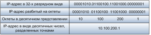
Для
удобства работы с IP-адресами 32-разрядную
последовательность обычно разделяют
на 4 части по 8 бит (октеты), каждый октет
переводят в десятичное число и при
записи разделяют эти числа точками. В
таком виде IP-адреса занимают гораздо
меньше места и намного легче запоминаются,
в соответствии с таблицей.
IP-адрес
назначается администратором во время
конфигурирования компьютеров и
маршрутизаторов. IP-адрес состоит из
двух частей: номера сети и номера узла.
Номер сети может быть выбран администратором
произвольно, либо назначен по рекомендации
специального подразделения Internet
(Internet Network Information Center, InterNIC), если сеть
должна работать как составная часть
Internet. Обычно поставщики услуг Internet
получают диапазоны адресов у подразделений
InterNIC, а затем распределяют их между
своими абонентами. Но¬мер узла в протоколе
IP назначается независимо от локального
адреса узла. Маршрутизатор по определению
входит сразу в несколько сетей. Поэтому
каждый порт маршрутизатора имеет
собственный IP-адрес. Конечный узел также
может входить в несколько IP-сетей. В
этом случае компьютер должен иметь
несколько IP-адресов, по числу сетевых
связей. Таким образом, IP-адрес характеризует
не отдельный компьютер или маршрутизатор,
а одно сетевое соединение.
-
Стек
протоколов TCP/IP – формат адреса
Стек
протоколов TCP/IP
Это
стандартизованный набор сетевых
протоколов. В настоящее время — это
основной набор протоколов взаимодействия
в Интернете. Более подробно об этом
стеке протоколов и не только о нем можно
прочитать в этой статье.
В
состав стека протоколов TCP/IP входят два
основных протокола: IP, TCP и несколько
вспомогательных протоколов.
-
Протокол
IP (Internet Protocol) —
основной протокол сетевого уровня.
Определяет способ адресации на сетевом
уровне. -
Протокол
TCP (Transmission Control Protocol)
— протокол, обеспечивающий гарантированную
доставку данных.
Как
работают эти протоколы?
Протокол
IP задает формат адреса узла (поэтому
адреса компьютеров называются IP-адресами)
и доставляет пакет данных.
Однако,
на одном узле (компьютере сети) может
функционировать параллельно несколько
программ, которым требуется доступ к
сети. Следовательно, данные внутри
компьютерной системы должны распределяться
между программами. Поэтому, при передаче
данных по сети недостаточно просто
адресовать конкретный узел. Необходимо
также идентифицировать программу-получателя,
что невозможно осуществить средствами
протокола IP.
Другой
серьезной проблемой IP является
невозможность передачи больших массивов
данных. Протокол IP разбивает передаваемые
данные на пакеты, каждый из которых
передается в сеть независимо от других.
В случае если какие-либо пакеты потерялись,
то модуль IP на принимающей стороне не
сможет обнаружить потерю, т.е. целостность
данных будет нарушена.
Для
решения этих проблем разработан протокол
TCP.
Каждой
программе назначается номер TCP- порта
в соответствии с ее функциональным
назначением на основе определенных
стандартов. Порт можно рассматривать
как ячейку в почтовом отделении связи.
Протокол IP определяет только адрес
почтового отделения, а протокол TCP
положит конверт в нужную ячейку.
Таким
образом, стек протоколов IP и TCP обеспечивают
полную адресацию:
-
Номер
TCP-порта позволяет однозначно
идентифицировать программу на компьютере
сети, -
Компьютер
в сети однозначно определяется
IP-адресом.
Следовательно,
комбинация IP-адреса и номера порта
позволяет однозначно идентифицировать
программу в сети. Такой комбинированный
адрес называется сокетом (socket).
Дополнительно
к этому, протокол TCP обеспечивает
гарантированную доставку данных. Это
обеспечивается тем, что принимающий
компьютер подтверждает успешный прием
данных. Если передающий компьютер не
получает подтверждения, он пытается
произвести повторную передачу.
IP-адреса,
IP-сети. Подсети и маски подсетей
Более
подробно об этом читаем в
этой статье.
IP-адреса
Каждый
компьютер в локальной сети имеет свой
уникальный адрес, так же как человек
имеет свой почтовый адрес. Именно по
этим адресам компьютеры находят друг
друга в сети. Двух одинаковых адресов
в одной сети быть не должно. Формат
адреса стандартный и определен протоколом
IP.
IP-адрес
компьютера записывается в 32 разрядах
(4 октета). Каждый октет содержит десятичное
число от 0 до 255 (в двоичном виде запись
представляет последовательность 0 и
1). IP-адрес представляет собой четыре
числа, разделяемых точкой. Например,
компьютер с IP-адресом 192.168.3.24. Общее
число IP-адресов составляет 4,2 млрд., все
адреса уникальны.
IP-адрес
может быть присвоен не только компьютеру,
но и другим сетевым устройствам, например,
принт-серверу или маршрутизатору.
Поэтому все устройства в сети принято
называть узлами или хостами.
Одно
и тоже физическое устройство (компьютер
или др.) может иметь несколько IP-адресов.
Например, если в компьютер установлено
несколько сетевых адаптеров, то каждый
адаптер должен иметь свой уникальный
IP-адрес. Такие компьютеры используются
для соединения нескольких локальных
сетей и называются маршрутизаторами.
Соседние файлы в предмете [НЕСОРТИРОВАННОЕ]
- #
- #
14.03.20151.54 Mб17DIPLOM_Podshivalova[1].rtf
- #
- #
- #
- #
- #
- #
- #
- #
- #
| Communication protocol | |
| Developer(s) | Vint Cerf and Bob Kahn |
|---|---|
| Introduction | 1974 |
| Based on | Transmission Control Program |
| OSI layer | 4 |
| RFC(s) | RFC 9293 |
The Transmission Control Protocol (TCP) is one of the main protocols of the Internet protocol suite. It originated in the initial network implementation in which it complemented the Internet Protocol (IP). Therefore, the entire suite is commonly referred to as TCP/IP. TCP provides reliable, ordered, and error-checked delivery of a stream of octets (bytes) between applications running on hosts communicating via an IP network. Major internet applications such as the World Wide Web, email, remote administration, and file transfer rely on TCP, which is part of the Transport Layer of the TCP/IP suite. SSL/TLS often runs on top of TCP.
TCP is connection-oriented, and a connection between client and server is established before data can be sent. The server must be listening (passive open) for connection requests from clients before a connection is established. Three-way handshake (active open), retransmission, and error detection adds to reliability but lengthens latency. Applications that do not require reliable data stream service may use the User Datagram Protocol (UDP) instead, which provides a connectionless datagram service that prioritizes time over reliability. TCP employs network congestion avoidance. However, there are vulnerabilities in TCP, including denial of service, connection hijacking, TCP veto, and reset attack.
Historical origin[edit]
In May 1974, Vint Cerf and Bob Kahn described an internetworking protocol for sharing resources using packet switching among network nodes.[1] The authors had been working with Gérard Le Lann to incorporate concepts from the French CYCLADES project into the new network.[2] The specification of the resulting protocol, RFC 675 (Specification of Internet Transmission Control Program), was written by Vint Cerf, Yogen Dalal, and Carl Sunshine, and published in December 1974. It contains the first attested use of the term internet, as a shorthand for internetwork.[3]
A central control component of this model was the Transmission Control Program that incorporated both connection-oriented links and datagram services between hosts. The monolithic Transmission Control Program was later divided into a modular architecture consisting of the Transmission Control Protocol and the Internet Protocol. This resulted in a networking model that became known informally as TCP/IP, although formally it was variously referred to as the Department of Defense (DOD) model, and ARPANET model, and eventually also as the Internet Protocol Suite.
In 2004, Vint Cerf and Bob Kahn received the Turing Award for their foundational work on TCP/IP.[4][5]
Network function[edit]
The Transmission Control Protocol provides a communication service at an intermediate level between an application program and the Internet Protocol. It provides host-to-host connectivity at the transport layer of the Internet model. An application does not need to know the particular mechanisms for sending data via a link to another host, such as the required IP fragmentation to accommodate the maximum transmission unit of the transmission medium. At the transport layer, TCP handles all handshaking and transmission details and presents an abstraction of the network connection to the application typically through a network socket interface.
At the lower levels of the protocol stack, due to network congestion, traffic load balancing, or unpredictable network behaviour, IP packets may be lost, duplicated, or delivered out of order. TCP detects these problems, requests re-transmission of lost data, rearranges out-of-order data and even helps minimize network congestion to reduce the occurrence of the other problems. If the data still remains undelivered, the source is notified of this failure. Once the TCP receiver has reassembled the sequence of octets originally transmitted, it passes them to the receiving application. Thus, TCP abstracts the application’s communication from the underlying networking details.
TCP is used extensively by many internet applications, including the World Wide Web (WWW), email, File Transfer Protocol, Secure Shell, peer-to-peer file sharing, and streaming media.
TCP is optimized for accurate delivery rather than timely delivery and can incur relatively long delays (on the order of seconds) while waiting for out-of-order messages or re-transmissions of lost messages. Therefore, it is not particularly suitable for real-time applications such as voice over IP. For such applications, protocols like the Real-time Transport Protocol (RTP) operating over the User Datagram Protocol (UDP) are usually recommended instead.[6]
TCP is a reliable byte stream delivery service which guarantees that all bytes received will be identical and in the same order as those sent. Since packet transfer by many networks is not reliable, TCP achieves this using a technique known as positive acknowledgement with re-transmission. This requires the receiver to respond with an acknowledgement message as it receives the data. The sender keeps a record of each packet it sends and maintains a timer from when the packet was sent. The sender re-transmits a packet if the timer expires before receiving the acknowledgement. The timer is needed in case a packet gets lost or corrupted.[6]
While IP handles actual delivery of the data, TCP keeps track of segments — the individual units of data transmission that a message is divided into for efficient routing through the network. For example, when an HTML file is sent from a web server, the TCP software layer of that server divides the file into segments and forwards them individually to the internet layer in the network stack. The internet layer software encapsulates each TCP segment into an IP packet by adding a header that includes (among other data) the destination IP address. When the client program on the destination computer receives them, the TCP software in the transport layer re-assembles the segments and ensures they are correctly ordered and error-free as it streams the file contents to the receiving application.
TCP segment structure[edit]
Transmission Control Protocol accepts data from a data stream, divides it into chunks, and adds a TCP header creating a TCP segment. The TCP segment is then encapsulated into an Internet Protocol (IP) datagram, and exchanged with peers.[7]
The term TCP packet appears in both informal and formal usage, whereas in more precise terminology segment refers to the TCP protocol data unit (PDU), datagram[8]: 5–6 to the IP PDU, and frame to the data link layer PDU:
Processes transmit data by calling on the TCP and passing buffers of data as arguments. The TCP packages the data from these buffers into segments and calls on the internet module [e.g. IP] to transmit each segment to the destination TCP.[9]
A TCP segment consists of a segment header and a data section. The segment header contains 10 mandatory fields, and an optional extension field (Options, pink background in table). The data section follows the header and is the payload data carried for the application. The length of the data section is not specified in the segment header; it can be calculated by subtracting the combined length of the segment header and IP header from the total IP datagram length specified in the IP header.
| Offsets | Octet | 0 | 1 | 2 | 3 | ||||||||||||||||||||||||||||
|---|---|---|---|---|---|---|---|---|---|---|---|---|---|---|---|---|---|---|---|---|---|---|---|---|---|---|---|---|---|---|---|---|---|
| Octet | Bit | 7 | 6 | 5 | 4 | 3 | 2 | 1 | 0 | 7 | 6 | 5 | 4 | 3 | 2 | 1 | 0 | 7 | 6 | 5 | 4 | 3 | 2 | 1 | 0 | 7 | 6 | 5 | 4 | 3 | 2 | 1 | 0 |
| 0 | 0 | Source port | Destination port | ||||||||||||||||||||||||||||||
| 4 | 32 | Sequence number | |||||||||||||||||||||||||||||||
| 8 | 64 | Acknowledgment number (if ACK set) | |||||||||||||||||||||||||||||||
| 12 | 96 | Data offset | Reserved 0 0 0 | NS | CWR | ECE | URG | ACK | PSH | RST | SYN | FIN | Window Size | ||||||||||||||||||||
| 16 | 128 | Checksum | Urgent pointer (if URG set) | ||||||||||||||||||||||||||||||
| 20 | 160 | Options (if data offset > 5. Padded at the end with «0» bits if necessary.) | |||||||||||||||||||||||||||||||
| ⋮ | ⋮ | ||||||||||||||||||||||||||||||||
| 60 | 480 |
- Source port (16 bits)
- Identifies the sending port.
- Destination port (16 bits)
- Identifies the receiving port.
- Sequence number (32 bits)
- Has a dual role:
- If the SYN flag is set (1), then this is the initial sequence number. The sequence number of the actual first data byte and the acknowledged number in the corresponding ACK are then this sequence number plus 1.
- If the SYN flag is clear (0), then this is the accumulated sequence number of the first data byte of this segment for the current session.
- Acknowledgment number (32 bits)
- If the ACK flag is set then the value of this field is the next sequence number that the sender of the ACK is expecting. This acknowledges receipt of all prior bytes (if any). The first ACK sent by each end acknowledges the other end’s initial sequence number itself, but no data.
- Data offset (4 bits)
- Specifies the size of the TCP header in 32-bit words. The minimum size header is 5 words and the maximum is 15 words thus giving the minimum size of 20 bytes and maximum of 60 bytes, allowing for up to 40 bytes of options in the header. This field gets its name from the fact that it is also the offset from the start of the TCP segment to the actual data.
- Reserved (3 bits)
- For future use and should be set to zero.
- Flags (9 bits)
- Contains 9 1-bit flags (control bits) as follows:
- NS (1 bit): ECN-nonce — concealment protection[a]
- CWR (1 bit): Congestion window reduced (CWR) flag is set by the sending host to indicate that it received a TCP segment with the ECE flag set and had responded in congestion control mechanism.[b]
- ECE (1 bit): ECN-Echo has a dual role, depending on the value of the SYN flag. It indicates:
-
- If the SYN flag is set (1), that the TCP peer is ECN capable.
- If the SYN flag is clear (0), that a packet with Congestion Experienced flag set (ECN=11) in the IP header was received during normal transmission.[b] This serves as an indication of network congestion (or impending congestion) to the TCP sender.
- URG (1 bit): Indicates that the Urgent pointer field is significant
- ACK (1 bit): Indicates that the Acknowledgment field is significant. All packets after the initial SYN packet sent by the client should have this flag set.
- PSH (1 bit): Push function. Asks to push the buffered data to the receiving application.
- RST (1 bit): Reset the connection
- SYN (1 bit): Synchronize sequence numbers. Only the first packet sent from each end should have this flag set. Some other flags and fields change meaning based on this flag, and some are only valid when it is set, and others when it is clear.
- FIN (1 bit): Last packet from sender
- Window size (16 bits)
- The size of the receive window, which specifies the number of window size units[c] that the sender of this segment is currently willing to receive.[d] (See § Flow control and § Window scaling.)
- Checksum (16 bits)
- The 16-bit checksum field is used for error-checking of the TCP header, the payload and an IP pseudo-header. The pseudo-header consists of the source IP address, the destination IP address, the protocol number for the TCP protocol (6) and the length of the TCP headers and payload (in bytes).
- Urgent pointer (16 bits)
- If the URG flag is set, then this 16-bit field is an offset from the sequence number indicating the last urgent data byte.
- Options (Variable 0–320 bits, in units of 32 bits)
- The length of this field is determined by the data offset field. Options have up to three fields: Option-Kind (1 byte), Option-Length (1 byte), Option-Data (variable). The Option-Kind field indicates the type of option and is the only field that is not optional. Depending on Option-Kind value, the next two fields may be set. Option-Length indicates the total length of the option, and Option-Data contains data associated with the option, if applicable. For example, an Option-Kind byte of 1 indicates that this is a no operation option used only for padding, and does not have an Option-Length or Option-Data fields following it. An Option-Kind byte of 0 marks the end of options, and is also only one byte. An Option-Kind byte of 2 is used to indicate Maximum Segment Size option, and will be followed by an Option-Length byte specifying the length of the MSS field. Option-Length is the total length of the given options field, including Option-Kind and Option-Length fields. So while the MSS value is typically expressed in two bytes, Option-Length will be 4. As an example, an MSS option field with a value of 0x05B4 is coded as (0x02 0x04 0x05B4) in the TCP options section.
- Some options may only be sent when SYN is set; they are indicated below as
[SYN]. Option-Kind and standard lengths given as (Option-Kind, Option-Length).
-
Option-Kind Option-Length Option-Data Purpose Notes 0 — — End of options list 1 — — No operation This may be used to align option fields on 32-bit boundaries for better performance. 2 4 SS Maximum segment size See § Maximum segment size [SYN]3 3 S Window scale See § Window scaling for details[10] [SYN]4 2 — Selective Acknowledgement permitted See § Selective acknowledgments for details[11]: §2 [SYN]5 N (10, 18, 26, or 34) BBBB, EEEE, … Selective ACKnowledgement (SACK)[11]: §3 These first two bytes are followed by a list of 1–4 blocks being selectively acknowledged, specified as 32-bit begin/end pointers. 8 10 TTTT, EEEE Timestamp and echo of previous timestamp See § TCP timestamps for details[12]
- The remaining Option-Kind values are historical, obsolete, experimental, not yet standardized, or unassigned. Option number assignments are maintained by the IANA.[13]
- Padding
- The TCP header padding is used to ensure that the TCP header ends, and data begins, on a 32-bit boundary. The padding is composed of zeros.[9]
Protocol operation[edit]

A Simplified TCP State Diagram. See TCP EFSM diagram for more detailed diagrams, including detail on the ESTABLISHED state.
TCP protocol operations may be divided into three phases. Connection establishment is a multi-step handshake process that establishes a connection before entering the data transfer phase. After data transfer is completed, the connection termination closes the connection and releases all allocated resources.
A TCP connection is managed by an operating system through a resource that represents the local end-point for communications, the Internet socket. During the lifetime of a TCP connection, the local end-point undergoes a series of state changes:[14]
| State | Endpoint | Description |
|---|---|---|
| LISTEN | Server | Waiting for a connection request from any remote TCP end-point. |
| SYN-SENT | Client | Waiting for a matching connection request after having sent a connection request. |
| SYN-RECEIVED | Server | Waiting for a confirming connection request acknowledgment after having both received and sent a connection request. |
| ESTABLISHED | Server and client | An open connection, data received can be delivered to the user. The normal state for the data transfer phase of the connection. |
| FIN-WAIT-1 | Server and client | Waiting for a connection termination request from the remote TCP, or an acknowledgment of the connection termination request previously sent. |
| FIN-WAIT-2 | Server and client | Waiting for a connection termination request from the remote TCP. |
| CLOSE-WAIT | Server and client | Waiting for a connection termination request from the local user. |
| CLOSING | Server and client | Waiting for a connection termination request acknowledgment from the remote TCP. |
| LAST-ACK | Server and client | Waiting for an acknowledgment of the connection termination request previously sent to the remote TCP (which includes an acknowledgment of its connection termination request). |
| TIME-WAIT | Server or client | Waiting for enough time to pass to be sure that all remaining packets on the connection have expired. |
| CLOSED | Server and client | No connection state at all. |
Connection establishment[edit]
Before a client attempts to connect with a server, the server must first bind to and listen at a port to open it up for connections: this is called a passive open. Once the passive open is established, a client may establish a connection by initiating an active open using the three-way (or 3-step) handshake:
- SYN: The active open is performed by the client sending a SYN to the server. The client sets the segment’s sequence number to a random value A.
- SYN-ACK: In response, the server replies with a SYN-ACK. The acknowledgment number is set to one more than the received sequence number i.e. A+1, and the sequence number that the server chooses for the packet is another random number, B.
- ACK: Finally, the client sends an ACK back to the server. The sequence number is set to the received acknowledgment value i.e. A+1, and the acknowledgment number is set to one more than the received sequence number i.e. B+1.
Steps 1 and 2 establish and acknowledge the sequence number for one direction. Steps 2 and 3 establish and acknowledge the sequence number for the other direction. Following the completion of these steps, both the client and server have received acknowledgments and a full-duplex communication is established.
Connection termination[edit]

The connection termination phase uses a four-way handshake, with each side of the connection terminating independently. When an endpoint wishes to stop its half of the connection, it transmits a FIN packet, which the other end acknowledges with an ACK. Therefore, a typical tear-down requires a pair of FIN and ACK segments from each TCP endpoint. After the side that sent the first FIN has responded with the final ACK, it waits for a timeout before finally closing the connection, during which time the local port is unavailable for new connections; this state lets the TCP client resend the final acknowledgement to the server in case the ACK is lost in transit. The time duration is implementation-dependent, but some common values are 30 seconds, 1 minute, and 2 minutes. After the timeout, the client enters the CLOSED state and the local port becomes available for new connections.[15]
It is also possible to terminate the connection by a 3-way handshake, when host A sends a FIN and host B replies with a FIN & ACK (combining two steps into one) and host A replies with an ACK.[16]
Some operating systems, such as Linux and HP-UX,[citation needed] implement a half-duplex close sequence. If the host actively closes a connection, while still having unread incoming data available, the host sends the signal RST (losing any received data) instead of FIN. This assures that a TCP application is aware there was a data loss.[17]
A connection can be in a half-open state, in which case one side has terminated the connection, but the other has not. The side that has terminated can no longer send any data into the connection, but the other side can. The terminating side should continue reading the data until the other side terminates as well.[citation needed]
Resource usage[edit]
Most implementations allocate an entry in a table that maps a session to a running operating system process. Because TCP packets do not include a session identifier, both endpoints identify the session using the client’s address and port. Whenever a packet is received, the TCP implementation must perform a lookup on this table to find the destination process. Each entry in the table is known as a Transmission Control Block or TCB. It contains information about the endpoints (IP and port), status of the connection, running data about the packets that are being exchanged and buffers for sending and receiving data.
The number of sessions in the server side is limited only by memory and can grow as new connections arrive, but the client must allocate an ephemeral port before sending the first SYN to the server. This port remains allocated during the whole conversation and effectively limits the number of outgoing connections from each of the client’s IP addresses. If an application fails to properly close unrequired connections, a client can run out of resources and become unable to establish new TCP connections, even from other applications.
Both endpoints must also allocate space for unacknowledged packets and received (but unread) data.
Data transfer[edit]
The Transmission Control Protocol differs in several key features compared to the User Datagram Protocol:
- Ordered data transfer: the destination host rearranges segments according to a sequence number[6]
- Retransmission of lost packets: any cumulative stream not acknowledged is retransmitted[6]
- Error-free data transfer: corrupted packets are treated as lost and are retransmitted[18]
- Flow control: limits the rate a sender transfers data to guarantee reliable delivery. The receiver continually hints the sender on how much data can be received. When the receiving host’s buffer fills, the next acknowledgment suspends the transfer and allows the data in the buffer to be processed.[6]
- Congestion control: lost packets (presumed due to congestion) trigger a reduction in data delivery rate[6]
Reliable transmission[edit]
TCP uses a sequence number to identify each byte of data. The sequence number identifies the order of the bytes sent from each computer so that the data can be reconstructed in order, regardless of any out-of-order delivery that may occur. The sequence number of the first byte is chosen by the transmitter for the first packet, which is flagged SYN. This number can be arbitrary, and should, in fact, be unpredictable to defend against TCP sequence prediction attacks.
Acknowledgements (ACKs) are sent with a sequence number by the receiver of data to tell the sender that data has been received to the specified byte. ACKs do not imply that the data has been delivered to the application, they merely signify that it is now the receiver’s responsibility to deliver the data.
Reliability is achieved by the sender detecting lost data and retransmitting it. TCP uses two primary techniques to identify loss. Retransmission timeout (RTO) and duplicate cumulative acknowledgements (DupAcks).
Dupack-based retransmission[edit]
If a single segment (say segment number 100) in a stream is lost, then the receiver cannot acknowledge packets above that segment number (100) because it uses cumulative ACKs. Hence the receiver acknowledges packet 99 again on the receipt of another data packet. This duplicate acknowledgement is used as a signal for packet loss. That is, if the sender receives three duplicate acknowledgements, it retransmits the last unacknowledged packet. A threshold of three is used because the network may reorder segments causing duplicate acknowledgements. This threshold has been demonstrated to avoid spurious retransmissions due to reordering.[19] Some TCP implementation use selective acknowledgements (SACKs) to provide explicit feedback about the segments that have been received. This greatly improves TCP’s ability to retransmit the right segments.
Timeout-based retransmission[edit]
When a sender transmits a segment, it initializes a timer with a conservative estimate of the arrival time of the acknowledgement. The segment is retransmitted if the timer expires, with a new timeout threshold of twice the previous value, resulting in exponential backoff behavior. Typically, the initial timer value is 

Error detection[edit]
Sequence numbers allow receivers to discard duplicate packets and properly sequence out-of-order packets. Acknowledgments allow senders to determine when to retransmit lost packets.
To assure correctness a checksum field is included; see § Checksum computation for details. The TCP checksum is a weak check by modern standards and is normally paired with a CRC integrity check at layer 2, below both TCP and IP, such as is used in PPP or the Ethernet frame. However, introduction of errors in packets between CRC-protected hops is common and the 16-bit TCP checksum catches most of these.[21]
Flow control[edit]
TCP uses an end-to-end flow control protocol to avoid having the sender send data too fast for the TCP receiver to receive and process it reliably. Having a mechanism for flow control is essential in an environment where machines of diverse network speeds communicate. For example, if a PC sends data to a smartphone that is slowly processing received data, the smartphone must be able to regulate the data flow so as not to be overwhelmed.[6]
TCP uses a sliding window flow control protocol. In each TCP segment, the receiver specifies in the receive window field the amount of additionally received data (in bytes) that it is willing to buffer for the connection. The sending host can send only up to that amount of data before it must wait for an acknowledgement and receive window update from the receiving host.

TCP sequence numbers and receive windows behave very much like a clock. The receive window shifts each time the receiver receives and acknowledges a new segment of data. Once it runs out of sequence numbers, the sequence number loops back to 0.
When a receiver advertises a window size of 0, the sender stops sending data and starts its persist timer. The persist timer is used to protect TCP from a deadlock situation that could arise if a subsequent window size update from the receiver is lost, and the sender cannot send more data until receiving a new window size update from the receiver. When the persist timer expires, the TCP sender attempts recovery by sending a small packet so that the receiver responds by sending another acknowledgement containing the new window size.
If a receiver is processing incoming data in small increments, it may repeatedly advertise a small receive window. This is referred to as the silly window syndrome, since it is inefficient to send only a few bytes of data in a TCP segment, given the relatively large overhead of the TCP header.
Congestion control[edit]
The final main aspect of TCP is congestion control. TCP uses a number of mechanisms to achieve high performance and avoid congestive collapse, a gridlock situation where network performance is severely degraded. These mechanisms control the rate of data entering the network, keeping the data flow below a rate that would trigger collapse. They also yield an approximately max-min fair allocation between flows.
Acknowledgments for data sent, or the lack of acknowledgments, are used by senders to infer network conditions between the TCP sender and receiver. Coupled with timers, TCP senders and receivers can alter the behavior of the flow of data. This is more generally referred to as congestion control or congestion avoidance.
Modern implementations of TCP contain four intertwined algorithms: slow start, congestion avoidance, fast retransmit, and fast recovery.[22]
In addition, senders employ a retransmission timeout (RTO) that is based on the estimated round-trip time (RTT) between the sender and receiver, as well as the variance in this round-trip time.[20] There are subtleties in the estimation of RTT. For example, senders must be careful when calculating RTT samples for retransmitted packets; typically they use Karn’s Algorithm or TCP timestamps.[23] These individual RTT samples are then averaged over time to create a smoothed round trip time (SRTT) using Jacobson’s algorithm. This SRTT value is what is used as the round-trip time estimate.
Enhancing TCP to reliably handle loss, minimize errors, manage congestion and go fast in very high-speed environments are ongoing areas of research and standards development. As a result, there are a number of TCP congestion avoidance algorithm variations.
Maximum segment size[edit]
The maximum segment size (MSS) is the largest amount of data, specified in bytes, that TCP is willing to receive in a single segment. For best performance, the MSS should be set small enough to avoid IP fragmentation, which can lead to packet loss and excessive retransmissions. To accomplish this, typically the MSS is announced by each side using the MSS option when the TCP connection is established. The option value is derived from the maximum transmission unit (MTU) size of the data link layer of the networks to which the sender and receiver are directly attached. TCP senders can use path MTU discovery to infer the minimum MTU along the network path between the sender and receiver, and use this to dynamically adjust the MSS to avoid IP fragmentation within the network.
MSS announcement may also be called MSS negotiation but, strictly speaking, the MSS is not negotiated. Two completely independent values of MSS are permitted for the two directions of data flow in a TCP connection,[24][9] so there is no need to agree on a common MSS configuration for a bidirectional connection.
Selective acknowledgments[edit]
Relying purely on the cumulative acknowledgment scheme employed by the original TCP can lead to inefficiencies when packets are lost. For example, suppose bytes with sequence number 1,000 to 10,999 are sent in 10 different TCP segments of equal size, and the second segment (sequence numbers 2,000 to 2,999) is lost during transmission. In a pure cumulative acknowledgment protocol, the receiver can only send a cumulative ACK value of 2,000 (the sequence number immediately following the last sequence number of the received data) and cannot say that it received bytes 3,000 to 10,999 successfully. Thus the sender may then have to resend all data starting with sequence number 2,000.
To alleviate this issue TCP employs the selective acknowledgment (SACK) option, defined in 1996 in RFC 2018, which allows the receiver to acknowledge discontinuous blocks of packets that were received correctly, in addition to the sequence number immediately following the last sequence number of the last contiguous byte received successively, as in the basic TCP acknowledgment. The acknowledgment can include a number of SACK blocks, where each SACK block is conveyed by the Left Edge of Block (the first sequence number of the block) and the Right Edge of Block (the sequence number immediately following the last sequence number of the block), with a Block being a contiguous range that the receiver correctly received. In the example above, the receiver would send an ACK segment with a cumulative ACK value of 2,000 and a SACK option header with sequence numbers 3,000 and 11,000. The sender would accordingly retransmit only the second segment with sequence numbers 2,000 to 2,999.
A TCP sender may interpret an out-of-order segment delivery as a lost segment. If it does so, the TCP sender will retransmit the segment previous to the out-of-order packet and slow its data delivery rate for that connection. The duplicate-SACK option, an extension to the SACK option that was defined in May 2000 in RFC 2883, solves this problem. The TCP receiver sends a D-ACK to indicate that no segments were lost, and the TCP sender can then reinstate the higher transmission rate.
The SACK option is not mandatory and comes into operation only if both parties support it. This is negotiated when a connection is established. SACK uses a TCP header option (see § TCP segment structure for details). The use of SACK has become widespread—all popular TCP stacks support it. Selective acknowledgment is also used in Stream Control Transmission Protocol (SCTP).
Window scaling[edit]
For more efficient use of high-bandwidth networks, a larger TCP window size may be used. A 16-bit TCP window size field controls the flow of data and its value is limited to 65,535 bytes. Since the size field cannot be expanded beyond this limit, a scaling factor is used. The TCP window scale option, as defined in RFC 1323, is an option used to increase the maximum window size to 1 gigabyte. Scaling up to these larger window sizes is necessary for TCP tuning.
The window scale option is used only during the TCP 3-way handshake. The window scale value represents the number of bits to left-shift the 16-bit window size field when interpreting it. The window scale value can be set from 0 (no shift) to 14 for each direction independently. Both sides must send the option in their SYN segments to enable window scaling in either direction.
Some routers and packet firewalls rewrite the window scaling factor during a transmission. This causes sending and receiving sides to assume different TCP window sizes. The result is non-stable traffic that may be very slow. The problem is visible on some sites behind a defective router.[25]
TCP timestamps[edit]
TCP timestamps, defined in RFC 1323 in 1992, can help TCP determine in which order packets were sent. TCP timestamps are not normally aligned to the system clock and start at some random value. Many operating systems will increment the timestamp for every elapsed millisecond; however, the RFC only states that the ticks should be proportional.
There are two timestamp fields:
- a 4-byte sender timestamp value (my timestamp)
- a 4-byte echo reply timestamp value (the most recent timestamp received from you).
TCP timestamps are used in an algorithm known as Protection Against Wrapped Sequence numbers, or PAWS. PAWS is used when the receive window crosses the sequence number wraparound boundary. In the case where a packet was potentially retransmitted, it answers the question: «Is this sequence number in the first 4 GB or the second?» And the timestamp is used to break the tie.
Also, the Eifel detection algorithm uses TCP timestamps to determine if retransmissions are occurring because packets are lost or simply out of order.[26]
TCP timestamps are enabled by default in Linux,[27] and disabled by default in Windows Server 2008, 2012 and 2016.[28]
Recent Statistics show that the level of TCP timestamp adoption has stagnated, at ~40%, owing to Windows Server dropping support since Windows Server 2008.[29]
Out-of-band data[edit]
It is possible to interrupt or abort the queued stream instead of waiting for the stream to finish. This is done by specifying the data as urgent. This marks the transmission as out-of-band data (OOB) and tells the receiving program to process it immediately. When finished, TCP informs the application and resumes the stream queue. An example is when TCP is used for a remote login session where the user can send a keyboard sequence that interrupts or aborts the remotely-running program without waiting for the program to finish its current transfer.[6]
The urgent pointer only alters the processing on the remote host and doesn’t expedite any processing on the network itself. The capability is implemented differently or poorly on different systems or may not be supported. Where it is available, it is prudent to assume only single bytes of OOB data will be reliably handled.[30][31] Since the feature is not frequently used, it is not well tested on some platforms and has been associated with vunerabilities, WinNuke for instance.
Forcing data delivery[edit]
Normally, TCP waits for 200 ms for a full packet of data to send (Nagle’s Algorithm tries to group small messages into a single packet). This wait creates small, but potentially serious delays if repeated constantly during a file transfer. For example, a typical send block would be 4 KB, a typical MSS is 1460, so 2 packets go out on a 10 Mbit/s ethernet taking ~1.2 ms each followed by a third carrying the remaining 1176 after a 197 ms pause because TCP is waiting for a full buffer.
In the case of telnet, each user keystroke is echoed back by the server before the user can see it on the screen. This delay would become very annoying.
Setting the socket option TCP_NODELAY overrides the default 200 ms send delay. Application programs use this socket option to force output to be sent after writing a character or line of characters.
The RFC defines the PSH push bit as «a message to the receiving TCP stack to send this data immediately up to the receiving application».[6] There is no way to indicate or control it in user space using Berkeley sockets and it is controlled by protocol stack only.[32]
Vulnerabilities[edit]
TCP may be attacked in a variety of ways. The results of a thorough security assessment of TCP, along with possible mitigations for the identified issues, were published in 2009,[33] and is currently[when?] being pursued within the IETF.[34]
Denial of service[edit]
By using a spoofed IP address and repeatedly sending purposely assembled SYN packets, followed by many ACK packets, attackers can cause the server to consume large amounts of resources keeping track of the bogus connections. This is known as a SYN flood attack. Proposed solutions to this problem include SYN cookies and cryptographic puzzles, though SYN cookies come with their own set of vulnerabilities.[35] Sockstress is a similar attack, that might be mitigated with system resource management.[36] An advanced DoS attack involving the exploitation of the TCP Persist Timer was analyzed in Phrack #66.[37] PUSH and ACK floods are other variants.[38]
Connection hijacking[edit]
An attacker who is able to eavesdrop a TCP session and redirect packets can hijack a TCP connection. To do so, the attacker learns the sequence number from the ongoing communication and forges a false segment that looks like the next segment in the stream. Such a simple hijack can result in one packet being erroneously accepted at one end. When the receiving host acknowledges the extra segment to the other side of the connection, synchronization is lost. Hijacking might be combined with Address Resolution Protocol (ARP) or routing attacks that allow taking control of the packet flow, so as to get permanent control of the hijacked TCP connection.[39]
Impersonating a different IP address was not difficult prior to RFC 1948, when the initial sequence number was easily guessable. That allowed an attacker to blindly send a sequence of packets that the receiver would believe to come from a different IP address, without the need to deploy ARP or routing attacks: it is enough to ensure that the legitimate host of the impersonated IP address is down, or bring it to that condition using denial-of-service attacks. This is why the initial sequence number is now chosen at random.
TCP veto[edit]
An attacker who can eavesdrop and predict the size of the next packet to be sent can cause the receiver to accept a malicious payload without disrupting the existing connection. The attacker injects a malicious packet with the sequence number and a payload size of the next expected packet. When the legitimate packet is ultimately received, it is found to have the same sequence number and length as a packet already received and is silently dropped as a normal duplicate packet—the legitimate packet is «vetoed» by the malicious packet. Unlike in connection hijacking, the connection is never desynchronized and communication continues as normal after the malicious payload is accepted. TCP veto gives the attacker less control over the communication, but makes the attack particularly resistant to detection. The large increase in network traffic from the ACK storm is avoided. The only evidence to the receiver that something is amiss is a single duplicate packet, a normal occurrence in an IP network. The sender of the vetoed packet never sees any evidence of an attack.[40]
Another vulnerability is the TCP reset attack.
TCP ports[edit]
TCP and UDP use port numbers to identify sending and receiving application end-points on a host, often called Internet sockets. Each side of a TCP connection has an associated 16-bit unsigned port number (0-65535) reserved by the sending or receiving application. Arriving TCP packets are identified as belonging to a specific TCP connection by its sockets, that is, the combination of source host address, source port, destination host address, and destination port. This means that a server computer can provide several clients with several services simultaneously, as long as a client takes care of initiating any simultaneous connections to one destination port from different source ports.
Port numbers are categorized into three basic categories: well-known, registered, and dynamic/private. The well-known ports are assigned by the Internet Assigned Numbers Authority (IANA) and are typically used by system-level or root processes. Well-known applications running as servers and passively listening for connections typically use these ports. Some examples include: FTP (20 and 21), SSH (22), TELNET (23), SMTP (25), HTTP over SSL/TLS (443), and HTTP (80). Note, as of the latest standard, HTTP/3, QUIC is used as a transport instead of TCP. Registered ports are typically used by end user applications as ephemeral source ports when contacting servers, but they can also identify named services that have been registered by a third party. Dynamic/private ports can also be used by end user applications, but are less commonly so. Dynamic/private ports do not contain any meaning outside of any particular TCP connection.
Network Address Translation (NAT), typically uses dynamic port numbers, on the («Internet-facing») public side, to disambiguate the flow of traffic that is passing between a public network and a private subnetwork, thereby allowing many IP addresses (and their ports) on the subnet to be serviced by a single public-facing address.
Development[edit]
TCP is a complex protocol. However, while significant enhancements have been made and proposed over the years, its most basic operation has not changed significantly since its first specification RFC 675 in 1974, and the v4 specification RFC 793, published in September 1981. RFC 1122, Host Requirements for Internet Hosts, clarified a number of TCP protocol implementation requirements. A list of the 8 required specifications and over 20 strongly encouraged enhancements is available in RFC 7414. Among this list is RFC 2581, TCP Congestion Control, one of the most important TCP-related RFCs in recent years, describes updated algorithms that avoid undue congestion. In 2001, RFC 3168 was written to describe Explicit Congestion Notification (ECN), a congestion avoidance signaling mechanism.
The original TCP congestion avoidance algorithm was known as «TCP Tahoe», but many alternative algorithms have since been proposed (including TCP Reno, TCP Vegas, FAST TCP, TCP New Reno, and TCP Hybla).
TCP Interactive (iTCP) [41] is a research effort into TCP extensions that allows applications to subscribe to TCP events and register handler components that can launch applications for various purposes, including application-assisted congestion control.
Multipath TCP (MPTCP) [42][43] is an ongoing effort within the IETF that aims at allowing a TCP connection to use multiple paths to maximize resource usage and increase redundancy. The redundancy offered by Multipath TCP in the context of wireless networks enables the simultaneous utilization of different networks, which brings higher throughput and better handover capabilities. Multipath TCP also brings performance benefits in datacenter environments.[44] The reference implementation[45] of Multipath TCP is being developed in the Linux kernel.[46] Multipath TCP is used to support the Siri voice recognition application on iPhones, iPads and Macs [47]
tcpcrypt is an extension proposed in July 2010 to provide transport-level encryption directly in TCP itself. It is designed to work transparently and not require any configuration. Unlike TLS (SSL), tcpcrypt itself does not provide authentication, but provides simple primitives down to the application to do that. As of 2010, the first tcpcrypt IETF draft has been published and implementations exist for several major platforms.
TCP Fast Open is an extension to speed up the opening of successive TCP connections between two endpoints. It works by skipping the three-way handshake using a cryptographic «cookie». It is similar to an earlier proposal called T/TCP, which was not widely adopted due to security issues.[48] TCP Fast Open was published as RFC 7413 in 2014.[49]
Proposed in May 2013, Proportional Rate Reduction (PRR) is a TCP extension developed by Google engineers. PRR ensures that the TCP window size after recovery is as close to the slow start threshold as possible.[50] The algorithm is designed to improve the speed of recovery and is the default congestion control algorithm in Linux 3.2+ kernels.[51]
Deprecated proposals[edit]
TCP Cookie Transactions (TCPCT) is an extension proposed in December 2009[52] to secure servers against denial-of-service attacks. Unlike SYN cookies, TCPCT does not conflict with other TCP extensions such as window scaling. TCPCT was designed due to necessities of DNSSEC, where servers have to handle large numbers of short-lived TCP connections. In 2016, TCPCT was deprecated in favor of TCP Fast Open. Status of the original RFC was changed to «historic».[53]
TCP over wireless networks[edit]
TCP was originally designed for wired networks. Packet loss is considered to be the result of network congestion and the congestion window size is reduced dramatically as a precaution. However, wireless links are known to experience sporadic and usually temporary losses due to fading, shadowing, hand off, interference, and other radio effects, that are not strictly congestion. After the (erroneous) back-off of the congestion window size, due to wireless packet loss, there may be a congestion avoidance phase with a conservative decrease in window size. This causes the radio link to be underutilized. Extensive research on combating these harmful effects has been conducted. Suggested solutions can be categorized as end-to-end solutions, which require modifications at the client or server,[54] link layer solutions, such as Radio Link Protocol (RLP) in cellular networks, or proxy-based solutions which require some changes in the network without modifying end nodes.[54][55]
A number of alternative congestion control algorithms, such as Vegas, Westwood, Veno, and Santa Cruz, have been proposed to help solve the wireless problem.[citation needed]
Hardware implementations[edit]
One way to overcome the processing power requirements of TCP is to build hardware implementations of it, widely known as TCP offload engines (TOE). The main problem of TOEs is that they are hard to integrate into computing systems, requiring extensive changes in the operating system of the computer or device. One company to develop such a device was Alacritech.
Wire image and ossification[edit]
The wire image of TCP provides significant information-gathering and modification opportunities to on-path observers, as the protocol metadata is transmitted in cleartext.[56][57] While this transparency is useful to network operators and researchers,[59] information gathered from protocol metadata may reduce the end-user’s privacy.[60] This visibility and malleability of metadata has led to TCP being difficult to extend—a case of protocol ossification—as any intermediate node (a ‘middlebox’) can make decisions based on that metadata or even modify it,[61][62] breaking the end-to-end principle.[63] One measurement found that a third of paths across the Internet encounter at least one intermediary that modifies TCP metadata, and 6.5% of paths encounter harmful ossifying effects from intermediaries.[64] Avoiding extensibility hazards from intermediaries placed significant constraints on the design of MPTCP,[65][66] and difficulties caused by intermediaries have hindered the deployment of TCP Fast Open in web browsers.[67] Another source of ossification is the difficulty of modification of TCP functions at the endpoints, typically in the operating system kernel[68] or in hardware with a TCP offload engine.[69]
Performance[edit]
As TCP provides applications with the abstraction of a reliable byte stream, it can suffer from head-of-line blocking: if packets are reordered or lost and need to be retransmitted (and thus arrive out-of-order), data from sequentially later parts of the stream may be received before sequentially earlier parts of the stream; however, the later data cannot typically be used until the earlier data has been received, incurring network latency. If multiple independent higher-level messages are encapsulated and multiplexed onto a single TCP connection, then head-of-line blocking can cause processing of a fully-received message that was sent later to wait for delivery of a message that was sent earlier.[70]
Acceleration[edit]
The idea of a TCP accelerator is to terminate TCP connections inside the network processor and then relay the data to a second connection toward the end system. The data packets that originate from the sender are buffered at the accelerator node, which is responsible for performing local retransmissions in the event of packet loss. Thus, in case of losses, the feedback loop between the sender and the receiver is shortened to the one between the acceleration node and the receiver which guarantees a faster delivery of data to the receiver.
Since TCP is a rate-adaptive protocol, the rate at which the TCP sender injects
packets into the network is directly proportional to the prevailing load condition within the network as well as the processing capacity of the receiver. The prevalent conditions within the network are judged by the sender on the basis of the acknowledgments received by it. The acceleration node splits the feedback loop between the sender and the receiver and thus guarantees a shorter round trip time (RTT) per packet. A shorter RTT is beneficial as it ensures a quicker response time to any changes in the network and a faster adaptation by the sender to combat these changes.
Disadvantages of the method include the fact that the TCP session has to be directed through the accelerator; this means that if routing changes, so that the accelerator is no longer in the path, the connection will be broken. It also destroys the end-to-end property of the TCP ack mechanism; when the ACK is received by the sender, the packet has been stored by the accelerator, not delivered to the receiver.
Debugging[edit]
A packet sniffer, which intercepts TCP traffic on a network link, can be useful in debugging networks, network stacks, and applications that use TCP by showing the user what packets are passing through a link. Some networking stacks support the SO_DEBUG socket option, which can be enabled on the socket using setsockopt. That option dumps all the packets, TCP states, and events on that socket, which is helpful in debugging. Netstat is another utility that can be used for debugging.
Alternatives[edit]
For many applications TCP is not appropriate. One problem (at least with normal implementations) is that the application cannot access the packets coming after a lost packet until the retransmitted copy of the lost packet is received. This causes problems for real-time applications such as streaming media, real-time multiplayer games and voice over IP (VoIP) where it is generally more useful to get most of the data in a timely fashion than it is to get all of the data in order.
For historical and performance reasons, most storage area networks (SANs) use Fibre Channel Protocol (FCP) over Fibre Channel connections.
Also, for embedded systems, network booting, and servers that serve simple requests from huge numbers of clients (e.g. DNS servers) the complexity of TCP can be a problem. Finally, some tricks such as transmitting data between two hosts that are both behind NAT (using STUN or similar systems) are far simpler without a relatively complex protocol like TCP in the way.
Generally, where TCP is unsuitable, the User Datagram Protocol (UDP) is used. This provides the application multiplexing and checksums that TCP does, but does not handle streams or retransmission, giving the application developer the ability to code them in a way suitable for the situation, or to replace them with other methods like forward error correction or interpolation.
Stream Control Transmission Protocol (SCTP) is another protocol that provides reliable stream oriented services similar to TCP. It is newer and considerably more complex than TCP, and has not yet seen widespread deployment. However, it is especially designed to be used in situations where reliability and near-real-time considerations are important.
Venturi Transport Protocol (VTP) is a patented proprietary protocol that is designed to replace TCP transparently to overcome perceived inefficiencies related to wireless data transport.
TCP also has issues in high-bandwidth environments. The TCP congestion avoidance algorithm works very well for ad-hoc environments where the data sender is not known in advance. If the environment is predictable, a timing based protocol such as Asynchronous Transfer Mode (ATM) can avoid TCP’s retransmits overhead.
UDP-based Data Transfer Protocol (UDT) has better efficiency and fairness than TCP in networks that have high bandwidth-delay product.[71]
Multipurpose Transaction Protocol (MTP/IP) is patented proprietary software that is designed to adaptively achieve high throughput and transaction performance in a wide variety of network conditions, particularly those where TCP is perceived to be inefficient.
Checksum computation[edit]
TCP checksum for IPv4[edit]
When TCP runs over IPv4, the method used to compute the checksum is defined as follows:[9]
The checksum field is the 16-bit ones’ complement of the ones’ complement sum of all 16-bit words in the header and text. The checksum computation needs to ensure the 16-bit alignment of the data being summed. If a segment contains an odd number of header and text octets, alignment can be achieved by padding the last octet with zeros on its right to form a 16-bit word for checksum purposes. The pad is not transmitted as part of the segment. While computing the checksum, the checksum field itself is replaced with zeros.
In other words, after appropriate padding, all 16-bit words are added using one’s complement arithmetic. The sum is then bitwise complemented and inserted as the checksum field. A pseudo-header that mimics the IPv4 packet header used in the checksum computation is shown in the table below.
| Bit offset | 0–3 | 4–7 | 8–15 | 16–31 |
|---|---|---|---|---|
| 0 | Source address | |||
| 32 | Destination address | |||
| 64 | Zeros | Protocol | TCP length | |
| 96 | Source port | Destination port | ||
| 128 | Sequence number | |||
| 160 | Acknowledgement number | |||
| 192 | Data offset | Reserved | Flags | Window |
| 224 | Checksum | Urgent pointer | ||
| 256 | Options (optional) | |||
| 256/288+ | Data |
The source and destination addresses are those of the IPv4 header. The protocol value is 6 for TCP (cf. List of IP protocol numbers). The TCP length field is the length of the TCP header and data (measured in octets).
TCP checksum for IPv6[edit]
When TCP runs over IPv6, the method used to compute the checksum is changed:[72]
Any transport or other upper-layer protocol that includes the addresses from the IP header in its checksum computation must be modified for use over IPv6, to include the 128-bit IPv6 addresses instead of 32-bit IPv4 addresses.
A pseudo-header that mimics the IPv6 header for computation of the checksum is shown below.
| Bit offset | 0–7 | 8–15 | 16–23 | 24–31 |
|---|---|---|---|---|
| 0 | Source address | |||
| 32 | ||||
| 64 | ||||
| 96 | ||||
| 128 | Destination address | |||
| 160 | ||||
| 192 | ||||
| 224 | ||||
| 256 | TCP length | |||
| 288 | Zeros | Next header = Protocol | ||
| 320 | Source port | Destination port | ||
| 352 | Sequence number | |||
| 384 | Acknowledgement number | |||
| 416 | Data offset | Reserved | Flags | Window |
| 448 | Checksum | Urgent pointer | ||
| 480 | Options (optional) | |||
| 480/512+ | Data |
- Source address: the one in the IPv6 header
- Destination address: the final destination; if the IPv6 packet doesn’t contain a Routing header, TCP uses the destination address in the IPv6 header, otherwise, at the originating node, it uses the address in the last element of the Routing header, and, at the receiving node, it uses the destination address in the IPv6 header.
- TCP length: the length of the TCP header and data
- Next Header: the protocol value for TCP
Checksum offload [edit]
Many TCP/IP software stack implementations provide options to use hardware assistance to automatically compute the checksum in the network adapter prior to transmission onto the network or upon reception from the network for validation. This may relieve the OS from using precious CPU cycles calculating the checksum. Hence, overall network performance is increased.
This feature may cause packet analyzers that are unaware or uncertain about the use of checksum offload to report invalid checksums in outbound packets that have not yet reached the network adapter.[73] This will only occur for packets that are intercepted before being transmitted by the network adapter; all packets transmitted by the network adaptor on the wire will have valid checksums.[74] This issue can also occur when monitoring packets being transmitted between virtual machines on the same host, where a virtual device driver may omit the checksum calculation (as an optimization), knowing that the checksum will be calculated later by the VM host kernel or its physical hardware.
RFC documents[edit]
- RFC 675 – Specification of Internet Transmission Control Program, December 1974 Version
- RFC 793 – TCP v4
- RFC 1122 – includes some error corrections for TCP
- RFC 1323 – TCP Extensions for High Performance [Obsoleted by RFC 7323]
- RFC 1379 – Extending TCP for Transactions—Concepts [Obsoleted by RFC 6247]
- RFC 1948 – Defending Against Sequence Number Attacks
- RFC 2018 – TCP Selective Acknowledgment Options
- RFC 5681 – TCP Congestion Control
- RFC 6247 – Moving the Undeployed TCP Extensions RFC 1072, 1106, 1110, 1145, 1146, 1379, 1644 and 1693 to Historic Status
- RFC 6298 – Computing TCP’s Retransmission Timer
- RFC 6824 – TCP Extensions for Multipath Operation with Multiple Addresses
- RFC 7323 – TCP Extensions for High Performance
- RFC 7414 – A Roadmap for TCP Specification Documents
- RFC 9293 – Transmission Control Protocol (TCP)
See also[edit]
- Connection-oriented communication
- List of TCP and UDP port numbers (a long list of ports and services)
- Micro-bursting (networking)
- T/TCP variant of TCP
- TCP global synchronization
- TCP pacing
- Transport layer § Comparison of transport layer protocols
- WTCP a proxy-based modification of TCP for wireless networks
Notes[edit]
- ^ Experimental: see RFC 3540
- ^ a b Added to header by RFC 3168
- ^ Windows size units are, by default, bytes.
- ^ Window size is relative to the segment identified by the sequence number in the acknowledgment field.
References[edit]
- ^ Vinton G. Cerf; Robert E. Kahn (May 1974). «A Protocol for Packet Network Intercommunication» (PDF). IEEE Transactions on Communications. 22 (5): 637–648. doi:10.1109/tcom.1974.1092259. Archived from the original (PDF) on March 4, 2016.
- ^ Bennett, Richard (September 2009). «Designed for Change: End-to-End Arguments, Internet Innovation, and the Net Neutrality Debate» (PDF). Information Technology and Innovation Foundation. p. 11. Retrieved 11 September 2017.
- ^ V. Cerf; Y. Dalal; C. Sunshine (December 1974). SPECIFICATION OF INTERNET TRANSMISSION CONTROL PROGRAM. Network Working Group. doi:10.17487/RFC0698. RFC 698. Obsolete. Obsoleted by RFC 7805. NIC 2. INWG 72.
- ^ «Robert E Kahn — A.M. Turing Award Laureate». amturing.acm.org.
- ^ «Vinton Cerf — A.M. Turing Award Laureate». amturing.acm.org.
- ^ a b c d e f g h i Comer, Douglas E. (2006). Internetworking with TCP/IP: Principles, Protocols, and Architecture. Vol. 1 (5th ed.). Prentice Hall. ISBN 978-0-13-187671-2.
- ^ «TCP (Transmission Control Protocol)». Retrieved 2019-06-26.
- ^ J. Postel, ed. (September 1981). INTERNET PROTOCOL — DARPA INTERNET PROGRAM PROTOCOL SPECIFICATION. IETF. doi:10.17487/RFC0791. STD 5. RFC 791. IEN 128, 123, 111, 80, 54, 44, 41, 28, 26. Internet Standard. Obsoletes RFC 760. Updated by RFC 1349, 2474 and 6864.
- ^ a b c d W. Eddy, ed. (August 2022). Transmission Control Protocol (TCP). Internet Engineering Task Force. doi:10.17487/RFC9293. ISSN 2070-1721. STD 7. RFC 9293. Internet Standard. Obsoletes RFC 793, 879, 2873, 6093, 6429, 6528 and 6691. Updates RFC 1011, 1122 and 5961.
- ^ TCP Extensions for High Performance. sec. 2.2. RFC 1323.
- ^ a b S. Floyd; J. Mahdavi; M. Mathis; A. Romanow (October 1996). TCP Selective Acknowledgment Options. IETF TCP Large Windows workgroup. doi:10.17487/RFC2018. RFC 2018. Proposed Standard. Obsoletes RFC 1072.
- ^ «RFC 1323, TCP Extensions for High Performance, Section 3.2».
- ^ «Transmission Control Protocol (TCP) Parameters: TCP Option Kind Numbers». IANA.
- ^ W. Eddy, ed. (August 2022). Transmission Control Protocol (TCP). Internet Engineering Task Force. doi:10.17487/RFC9293. ISSN 2070-1721. STD 7. RFC 9293. Internet Standard. sec. 3.3.2.
- ^ Kurose, James F. (2017). Computer networking : a top-down approach. Keith W. Ross (7th ed.). Harlow, England. p. 286. ISBN 978-0-13-359414-0. OCLC 936004518.
- ^ Tanenbaum, Andrew S. (2003-03-17). Computer Networks (Fourth ed.). Prentice Hall. ISBN 978-0-13-066102-9.
- ^ R. Braden, ed. (October 1989). Requirements for Internet Hosts — Communication Layers. Network Working Group. doi:10.17487/RFC1122. STD 3. RFC 1122. Internet Standard. sec. 4.2.2.13.
- ^ «TCP Definition». Retrieved 2011-03-12.
- ^ Mathis; Mathew; Semke; Mahdavi; Ott (1997). «The macroscopic behavior of the TCP congestion avoidance algorithm». ACM SIGCOMM Computer Communication Review. 27 (3): 67–82. CiteSeerX 10.1.1.40.7002. doi:10.1145/263932.264023. S2CID 1894993.
- ^ a b V. Paxson; M. Allman; J. Chu; M. Sargent (June 2011). Computing TCP’s Retransmission Timer. Internet Engineering Task Force. doi:10.17487/RFC6298. ISSN 2070-1721. RFC 6298. Proposed Standard. Obsoletes RFC 2988. Updates RFC 1122.
- ^ Stone; Partridge (2000). «When The CRC and TCP Checksum Disagree». ACM SIGCOMM Computer Communication Review: 309–319. CiteSeerX 10.1.1.27.7611. doi:10.1145/347059.347561. ISBN 978-1581132236. S2CID 9547018.
- ^ M. Allman; V. Paxson; E. Blanton (September 2009). TCP Congestion Control. IETF. doi:10.17487/RFC5681. RFC 5681. Draft Standard. Obsoletes RFC 2581.
- ^ D. Borman; B. Braden; V. Jacobson (September 2014). R. Scheffenegger (ed.). TCP Extensions for High Performance. Internet Engineering Task Force. doi:10.17487/RFC7323. ISSN 2070-1721. RFC 7323. Proposed Standard. Obsoletes RFC 1323.
- ^ R. Braden, ed. (October 1989). Requirements for Internet Hosts — Communication Layers. Network Working Group. doi:10.17487/RFC1122. STD 3. RFC 1122. Internet Standard. Updated by RFC 1349, 4379, 5884, 6093, 6298, 6633, 6864, 8029 and 9293.
- ^ «TCP window scaling and broken routers». LWN.net.
- ^ RFC 3522
- ^ «IP sysctl». Linux Kernel Documentation. Retrieved 15 December 2018.
- ^ Wang, Eve. «TCP timestamp is disabled». Technet — Windows Server 2012 Essentials. Microsoft. Archived from the original on 2018-12-15. Retrieved 2018-12-15.
- ^ David Murray; Terry Koziniec; Sebastian Zander; Michael Dixon; Polychronis Koutsakis (2017). «An Analysis of Changing Enterprise Network Traffic Characteristics» (PDF). The 23rd Asia-Pacific Conference on Communications (APCC 2017). Retrieved 3 October 2017.
- ^ Gont, Fernando (November 2008). «On the implementation of TCP urgent data». 73rd IETF meeting. Retrieved 2009-01-04.
- ^ Peterson, Larry (2003). Computer Networks. Morgan Kaufmann. p. 401. ISBN 978-1-55860-832-0.
- ^ Richard W. Stevens (November 2011). TCP/IP Illustrated. Vol. 1, The protocols. Addison-Wesley. pp. Chapter 20. ISBN 978-0-201-63346-7.
- ^ «Security Assessment of the Transmission Control Protocol (TCP)» (PDF). Archived from the original on March 6, 2009. Retrieved 2010-12-23.
{{cite web}}: CS1 maint: bot: original URL status unknown (link) - ^ Security Assessment of the Transmission Control Protocol (TCP)
- ^ Jakob Lell. «Quick Blind TCP Connection Spoofing with SYN Cookies». Retrieved 2014-02-05.
- ^ «Some insights about the recent TCP DoS (Denial of Service) vulnerabilities» (PDF).
- ^ «Exploiting TCP and the Persist Timer Infiniteness».
- ^ «PUSH and ACK Flood». f5.com.
- ^ «Laurent Joncheray, Simple Active Attack Against TCP, 1995″.
- ^ John T. Hagen; Barry E. Mullins (2013). TCP veto: A novel network attack and its application to SCADA protocols. Innovative Smart Grid Technologies (ISGT), 2013 IEEE PES. pp. 1–6. doi:10.1109/ISGT.2013.6497785. ISBN 978-1-4673-4896-6. S2CID 25353177.
- ^ «TCP Interactive». www.medianet.kent.edu.
- ^ J. Iyengar; C. Raiciu; S. Barre; M. Handley; A. Ford (March 2011). Architectural Guidelines for Multipath TCP Development. Internet Engineering Task Force (IETF). doi:10.17487/RFC6182. RFC 6182. Informational.
- ^ Alan Ford; C. Raiciu; M. Handley; O. Bonaventure (January 2013). TCP Extensions for Multipath Operation with Multiple Addresses. Internet Engineering Task Force. doi:10.17487/RFC6824. ISSN 2070-1721. RFC 6824. Experimental. Obsoleted by RFC 8624.
- ^ Raiciu; Barre; Pluntke; Greenhalgh; Wischik; Handley (2011). «Improving datacenter performance and robustness with multipath TCP». ACM SIGCOMM Computer Communication Review. 41 (4): 266. CiteSeerX 10.1.1.306.3863. doi:10.1145/2043164.2018467. Archived from the original on 2020-04-04. Retrieved 2011-06-29.
- ^ «MultiPath TCP — Linux Kernel implementation».
- ^ Raiciu; Paasch; Barre; Ford; Honda; Duchene; Bonaventure; Handley (2012). «How Hard Can It Be? Designing and Implementing a Deployable Multipath TCP». Usenix NSDI: 399–412.
- ^ Bonaventure; Seo (2016). «Multipath TCP Deployments». IETF Journal.
- ^ Michael Kerrisk (2012-08-01). «TCP Fast Open: expediting web services». LWN.net.
- ^ Yuchung Cheng; Jerry Chu; Sivasankar Radhakrishnan & Arvind Jain (December 2014). «TCP Fast Open». IETF. Retrieved 10 January 2015.
- ^ Mathis, Matt; Dukkipati, Nandita; Cheng, Yuchung (May 2013). «RFC 6937 — Proportional Rate Reduction for TCP». Retrieved 6 June 2014.
- ^ Grigorik, Ilya (2013). High-performance browser networking (1. ed.). Beijing: O’Reilly. ISBN 978-1449344764.
- ^ W. Simpson (January 2011). TCP Cookie Transactions (TCPCT). IETF. doi:10.17487/RFC6013. ISSN 2070-1721. RFC 6013. Obsolete. Obsoleted by RFC 7805.
- ^ A. Zimmermann; W. Eddy; L. Eggert (April 2016). Moving Outdated TCP Extensions and TCP-Related Documents to Historic or Informational Status. IETF. doi:10.17487/RFC7805. ISSN 2070-1721. RFC 7805. Informational. Obsoletes RFC 675, 721, 761, 813, 816, 879, 896 and 6013. Updates RFC 7414, 4291, 4338, 4391, 5072 and 5121.
- ^ a b «TCP performance over CDMA2000 RLP». Archived from the original on 2011-05-03. Retrieved 2010-08-30.
- ^ Muhammad Adeel & Ahmad Ali Iqbal (2004). TCP Congestion Window Optimization for CDMA2000 Packet Data Networks. International Conference on Information Technology (ITNG’07). pp. 31–35. doi:10.1109/ITNG.2007.190. ISBN 978-0-7695-2776-5. S2CID 8717768.
- ^ Trammell & Kuehlewind 2019, p. 6.
- ^ Hardie 2019, p. 3.
- ^ Fairhurst & Perkins 2021, 3. Research, Development, and Deployment.
- ^ Hardie 2019, p. 8.
- ^ Thomson & Pauly 2021, 2.3. Multi-party Interactions and Middleboxes.
- ^ Thomson & Pauly 2021, A.5. TCP.
- ^ Papastergiou et al. 2017, p. 620.
- ^ Edeline & Donnet 2019, p. 175-176.
- ^ Raiciu et al. 2012, p. 1.
- ^ Hesmans et al. 2013, p. 1.
- ^ Rybczyńska 2020.
- ^ Papastergiou et al. 2017, p. 621.
- ^ Corbet 2015.
- ^ Briscoe et al. 2006, p. 29-30.
- ^
Yunhong Gu, Xinwei Hong, and Robert L. Grossman.
«An Analysis of AIMD Algorithm with Decreasing Increases».
2004. - ^ S. Deering; R. Hinden (July 2017). Internet Protocol, Version 6 (IPv6) Specification. IETF. doi:10.17487/RFC8200. STD 86. RFC 8200. Internet Standard. Obsoletes RFC 2460.
- ^ «Wireshark: Offloading».
Wireshark captures packets before they are sent to the network adapter. It won’t see the correct checksum because it has not been calculated yet. Even worse, most OSes don’t bother initialize this data so you’re probably seeing little chunks of memory that you shouldn’t. New installations of Wireshark 1.2 and above disable IP, TCP, and UDP checksum validation by default. You can disable checksum validation in each of those dissectors by hand if needed.
- ^ «Wireshark: Checksums».
Checksum offloading often causes confusion as the network packets to be transmitted are handed over to Wireshark before the checksums are actually calculated. Wireshark gets these «empty» checksums and displays them as invalid, even though the packets will contain valid checksums when they leave the network hardware later.
Bibliography[edit]
- Trammell, Brian; Kuehlewind, Mirja (April 2019). The Wire Image of a Network Protocol. doi:10.17487/RFC8546. RFC 8546.
- Hardie, Ted, ed. (April 2019). Transport Protocol Path Signals. doi:10.17487/RFC8558. RFC 8558.
- Fairhurst, Gorry; Perkins, Colin (July 2021). Considerations around Transport Header Confidentiality, Network Operations, and the Evolution of Internet Transport Protocols. doi:10.17487/RFC9065. RFC 9065.
- Thomson, Martin; Pauly, Tommy (December 2021). Long-Term Viability of Protocol Extension Mechanisms. doi:10.17487/RFC9170. RFC 9170.
- Hesmans, Benjamin; Duchene, Fabien; Paasch, Christoph; Detal, Gregory; Bonaventure, Olivier (2013). Are TCP extensions middlebox-proof?. HotMiddlebox ’13. doi:10.1145/2535828.2535830.
- Corbet, Jonathan (8 December 2015). «Checksum offloads and protocol ossification». LWN.net.
- Briscoe, Bob; Brunstrom, Anna; Petlund, Andreas; Hayes, David; Ros, David; Tsang, Ing-Jyh; Gjessing, Stein; Fairhurst, Gorry; Griwodz, Carsten; Welzl, Michael (2016). «Reducing Internet Latency: A Survey of Techniques and Their Merits». IEEE Communications Surveys & Tutorials. 18 (3): 2149–2196. doi:10.1109/COMST.2014.2375213. hdl:2164/8018. S2CID 206576469.
- Papastergiou, Giorgos; Fairhurst, Gorry; Ros, David; Brunstrom, Anna; Grinnemo, Karl-Johan; Hurtig, Per; Khademi, Naeem; Tüxen, Michael; Welzl, Michael; Damjanovic, Dragana; Mangiante, Simone (2017). «De-Ossifying the Internet Transport Layer: A Survey and Future Perspectives». IEEE Communications Surveys & Tutorials. doi:10.1109/COMST.2016.2626780.
- Edeline, Korian; Donnet, Benoit (2019). A Bottom-Up Investigation of the Transport-Layer Ossification. 2019 Network Traffic Measurement and Analysis Conference (TMA). doi:10.23919/TMA.2019.8784690.
- Rybczyńska, Marta (13 March 2020). «A QUIC look at HTTP/3». LWN.net.
Further reading[edit]
- Stevens, W. Richard (1994-01-10). TCP/IP Illustrated, Volume 1: The Protocols. Addison-Wesley Pub. Co. ISBN 978-0-201-63346-7.
- Stevens, W. Richard; Wright, Gary R (1994). TCP/IP Illustrated, Volume 2: The Implementation. ISBN 978-0-201-63354-2.
- Stevens, W. Richard (1996). TCP/IP Illustrated, Volume 3: TCP for Transactions, HTTP, NNTP, and the UNIX Domain Protocols. ISBN 978-0-201-63495-2.**
External links[edit]
- Oral history interview with Robert E. Kahn
- IANA Port Assignments
- IANA TCP Parameters
- John Kristoff’s Overview of TCP (Fundamental concepts behind TCP and how it is used to transport data between two endpoints)
- Checksum example
- TCP tutorial
| Communication protocol | |
| Developer(s) | Vint Cerf and Bob Kahn |
|---|---|
| Introduction | 1974 |
| Based on | Transmission Control Program |
| OSI layer | 4 |
| RFC(s) | RFC 9293 |
The Transmission Control Protocol (TCP) is one of the main protocols of the Internet protocol suite. It originated in the initial network implementation in which it complemented the Internet Protocol (IP). Therefore, the entire suite is commonly referred to as TCP/IP. TCP provides reliable, ordered, and error-checked delivery of a stream of octets (bytes) between applications running on hosts communicating via an IP network. Major internet applications such as the World Wide Web, email, remote administration, and file transfer rely on TCP, which is part of the Transport Layer of the TCP/IP suite. SSL/TLS often runs on top of TCP.
TCP is connection-oriented, and a connection between client and server is established before data can be sent. The server must be listening (passive open) for connection requests from clients before a connection is established. Three-way handshake (active open), retransmission, and error detection adds to reliability but lengthens latency. Applications that do not require reliable data stream service may use the User Datagram Protocol (UDP) instead, which provides a connectionless datagram service that prioritizes time over reliability. TCP employs network congestion avoidance. However, there are vulnerabilities in TCP, including denial of service, connection hijacking, TCP veto, and reset attack.
Historical origin[edit]
In May 1974, Vint Cerf and Bob Kahn described an internetworking protocol for sharing resources using packet switching among network nodes.[1] The authors had been working with Gérard Le Lann to incorporate concepts from the French CYCLADES project into the new network.[2] The specification of the resulting protocol, RFC 675 (Specification of Internet Transmission Control Program), was written by Vint Cerf, Yogen Dalal, and Carl Sunshine, and published in December 1974. It contains the first attested use of the term internet, as a shorthand for internetwork.[3]
A central control component of this model was the Transmission Control Program that incorporated both connection-oriented links and datagram services between hosts. The monolithic Transmission Control Program was later divided into a modular architecture consisting of the Transmission Control Protocol and the Internet Protocol. This resulted in a networking model that became known informally as TCP/IP, although formally it was variously referred to as the Department of Defense (DOD) model, and ARPANET model, and eventually also as the Internet Protocol Suite.
In 2004, Vint Cerf and Bob Kahn received the Turing Award for their foundational work on TCP/IP.[4][5]
Network function[edit]
The Transmission Control Protocol provides a communication service at an intermediate level between an application program and the Internet Protocol. It provides host-to-host connectivity at the transport layer of the Internet model. An application does not need to know the particular mechanisms for sending data via a link to another host, such as the required IP fragmentation to accommodate the maximum transmission unit of the transmission medium. At the transport layer, TCP handles all handshaking and transmission details and presents an abstraction of the network connection to the application typically through a network socket interface.
At the lower levels of the protocol stack, due to network congestion, traffic load balancing, or unpredictable network behaviour, IP packets may be lost, duplicated, or delivered out of order. TCP detects these problems, requests re-transmission of lost data, rearranges out-of-order data and even helps minimize network congestion to reduce the occurrence of the other problems. If the data still remains undelivered, the source is notified of this failure. Once the TCP receiver has reassembled the sequence of octets originally transmitted, it passes them to the receiving application. Thus, TCP abstracts the application’s communication from the underlying networking details.
TCP is used extensively by many internet applications, including the World Wide Web (WWW), email, File Transfer Protocol, Secure Shell, peer-to-peer file sharing, and streaming media.
TCP is optimized for accurate delivery rather than timely delivery and can incur relatively long delays (on the order of seconds) while waiting for out-of-order messages or re-transmissions of lost messages. Therefore, it is not particularly suitable for real-time applications such as voice over IP. For such applications, protocols like the Real-time Transport Protocol (RTP) operating over the User Datagram Protocol (UDP) are usually recommended instead.[6]
TCP is a reliable byte stream delivery service which guarantees that all bytes received will be identical and in the same order as those sent. Since packet transfer by many networks is not reliable, TCP achieves this using a technique known as positive acknowledgement with re-transmission. This requires the receiver to respond with an acknowledgement message as it receives the data. The sender keeps a record of each packet it sends and maintains a timer from when the packet was sent. The sender re-transmits a packet if the timer expires before receiving the acknowledgement. The timer is needed in case a packet gets lost or corrupted.[6]
While IP handles actual delivery of the data, TCP keeps track of segments — the individual units of data transmission that a message is divided into for efficient routing through the network. For example, when an HTML file is sent from a web server, the TCP software layer of that server divides the file into segments and forwards them individually to the internet layer in the network stack. The internet layer software encapsulates each TCP segment into an IP packet by adding a header that includes (among other data) the destination IP address. When the client program on the destination computer receives them, the TCP software in the transport layer re-assembles the segments and ensures they are correctly ordered and error-free as it streams the file contents to the receiving application.
TCP segment structure[edit]
Transmission Control Protocol accepts data from a data stream, divides it into chunks, and adds a TCP header creating a TCP segment. The TCP segment is then encapsulated into an Internet Protocol (IP) datagram, and exchanged with peers.[7]
The term TCP packet appears in both informal and formal usage, whereas in more precise terminology segment refers to the TCP protocol data unit (PDU), datagram[8]: 5–6 to the IP PDU, and frame to the data link layer PDU:
Processes transmit data by calling on the TCP and passing buffers of data as arguments. The TCP packages the data from these buffers into segments and calls on the internet module [e.g. IP] to transmit each segment to the destination TCP.[9]
A TCP segment consists of a segment header and a data section. The segment header contains 10 mandatory fields, and an optional extension field (Options, pink background in table). The data section follows the header and is the payload data carried for the application. The length of the data section is not specified in the segment header; it can be calculated by subtracting the combined length of the segment header and IP header from the total IP datagram length specified in the IP header.
| Offsets | Octet | 0 | 1 | 2 | 3 | ||||||||||||||||||||||||||||
|---|---|---|---|---|---|---|---|---|---|---|---|---|---|---|---|---|---|---|---|---|---|---|---|---|---|---|---|---|---|---|---|---|---|
| Octet | Bit | 7 | 6 | 5 | 4 | 3 | 2 | 1 | 0 | 7 | 6 | 5 | 4 | 3 | 2 | 1 | 0 | 7 | 6 | 5 | 4 | 3 | 2 | 1 | 0 | 7 | 6 | 5 | 4 | 3 | 2 | 1 | 0 |
| 0 | 0 | Source port | Destination port | ||||||||||||||||||||||||||||||
| 4 | 32 | Sequence number | |||||||||||||||||||||||||||||||
| 8 | 64 | Acknowledgment number (if ACK set) | |||||||||||||||||||||||||||||||
| 12 | 96 | Data offset | Reserved 0 0 0 | NS | CWR | ECE | URG | ACK | PSH | RST | SYN | FIN | Window Size | ||||||||||||||||||||
| 16 | 128 | Checksum | Urgent pointer (if URG set) | ||||||||||||||||||||||||||||||
| 20 | 160 | Options (if data offset > 5. Padded at the end with «0» bits if necessary.) | |||||||||||||||||||||||||||||||
| ⋮ | ⋮ | ||||||||||||||||||||||||||||||||
| 60 | 480 |
- Source port (16 bits)
- Identifies the sending port.
- Destination port (16 bits)
- Identifies the receiving port.
- Sequence number (32 bits)
- Has a dual role:
- If the SYN flag is set (1), then this is the initial sequence number. The sequence number of the actual first data byte and the acknowledged number in the corresponding ACK are then this sequence number plus 1.
- If the SYN flag is clear (0), then this is the accumulated sequence number of the first data byte of this segment for the current session.
- Acknowledgment number (32 bits)
- If the ACK flag is set then the value of this field is the next sequence number that the sender of the ACK is expecting. This acknowledges receipt of all prior bytes (if any). The first ACK sent by each end acknowledges the other end’s initial sequence number itself, but no data.
- Data offset (4 bits)
- Specifies the size of the TCP header in 32-bit words. The minimum size header is 5 words and the maximum is 15 words thus giving the minimum size of 20 bytes and maximum of 60 bytes, allowing for up to 40 bytes of options in the header. This field gets its name from the fact that it is also the offset from the start of the TCP segment to the actual data.
- Reserved (3 bits)
- For future use and should be set to zero.
- Flags (9 bits)
- Contains 9 1-bit flags (control bits) as follows:
- NS (1 bit): ECN-nonce — concealment protection[a]
- CWR (1 bit): Congestion window reduced (CWR) flag is set by the sending host to indicate that it received a TCP segment with the ECE flag set and had responded in congestion control mechanism.[b]
- ECE (1 bit): ECN-Echo has a dual role, depending on the value of the SYN flag. It indicates:
-
- If the SYN flag is set (1), that the TCP peer is ECN capable.
- If the SYN flag is clear (0), that a packet with Congestion Experienced flag set (ECN=11) in the IP header was received during normal transmission.[b] This serves as an indication of network congestion (or impending congestion) to the TCP sender.
- URG (1 bit): Indicates that the Urgent pointer field is significant
- ACK (1 bit): Indicates that the Acknowledgment field is significant. All packets after the initial SYN packet sent by the client should have this flag set.
- PSH (1 bit): Push function. Asks to push the buffered data to the receiving application.
- RST (1 bit): Reset the connection
- SYN (1 bit): Synchronize sequence numbers. Only the first packet sent from each end should have this flag set. Some other flags and fields change meaning based on this flag, and some are only valid when it is set, and others when it is clear.
- FIN (1 bit): Last packet from sender
- Window size (16 bits)
- The size of the receive window, which specifies the number of window size units[c] that the sender of this segment is currently willing to receive.[d] (See § Flow control and § Window scaling.)
- Checksum (16 bits)
- The 16-bit checksum field is used for error-checking of the TCP header, the payload and an IP pseudo-header. The pseudo-header consists of the source IP address, the destination IP address, the protocol number for the TCP protocol (6) and the length of the TCP headers and payload (in bytes).
- Urgent pointer (16 bits)
- If the URG flag is set, then this 16-bit field is an offset from the sequence number indicating the last urgent data byte.
- Options (Variable 0–320 bits, in units of 32 bits)
- The length of this field is determined by the data offset field. Options have up to three fields: Option-Kind (1 byte), Option-Length (1 byte), Option-Data (variable). The Option-Kind field indicates the type of option and is the only field that is not optional. Depending on Option-Kind value, the next two fields may be set. Option-Length indicates the total length of the option, and Option-Data contains data associated with the option, if applicable. For example, an Option-Kind byte of 1 indicates that this is a no operation option used only for padding, and does not have an Option-Length or Option-Data fields following it. An Option-Kind byte of 0 marks the end of options, and is also only one byte. An Option-Kind byte of 2 is used to indicate Maximum Segment Size option, and will be followed by an Option-Length byte specifying the length of the MSS field. Option-Length is the total length of the given options field, including Option-Kind and Option-Length fields. So while the MSS value is typically expressed in two bytes, Option-Length will be 4. As an example, an MSS option field with a value of 0x05B4 is coded as (0x02 0x04 0x05B4) in the TCP options section.
- Some options may only be sent when SYN is set; they are indicated below as
[SYN]. Option-Kind and standard lengths given as (Option-Kind, Option-Length).
-
Option-Kind Option-Length Option-Data Purpose Notes 0 — — End of options list 1 — — No operation This may be used to align option fields on 32-bit boundaries for better performance. 2 4 SS Maximum segment size See § Maximum segment size [SYN]3 3 S Window scale See § Window scaling for details[10] [SYN]4 2 — Selective Acknowledgement permitted See § Selective acknowledgments for details[11]: §2 [SYN]5 N (10, 18, 26, or 34) BBBB, EEEE, … Selective ACKnowledgement (SACK)[11]: §3 These first two bytes are followed by a list of 1–4 blocks being selectively acknowledged, specified as 32-bit begin/end pointers. 8 10 TTTT, EEEE Timestamp and echo of previous timestamp See § TCP timestamps for details[12]
- The remaining Option-Kind values are historical, obsolete, experimental, not yet standardized, or unassigned. Option number assignments are maintained by the IANA.[13]
- Padding
- The TCP header padding is used to ensure that the TCP header ends, and data begins, on a 32-bit boundary. The padding is composed of zeros.[9]
Protocol operation[edit]
A Simplified TCP State Diagram. See TCP EFSM diagram for more detailed diagrams, including detail on the ESTABLISHED state.
TCP protocol operations may be divided into three phases. Connection establishment is a multi-step handshake process that establishes a connection before entering the data transfer phase. After data transfer is completed, the connection termination closes the connection and releases all allocated resources.
A TCP connection is managed by an operating system through a resource that represents the local end-point for communications, the Internet socket. During the lifetime of a TCP connection, the local end-point undergoes a series of state changes:[14]
| State | Endpoint | Description |
|---|---|---|
| LISTEN | Server | Waiting for a connection request from any remote TCP end-point. |
| SYN-SENT | Client | Waiting for a matching connection request after having sent a connection request. |
| SYN-RECEIVED | Server | Waiting for a confirming connection request acknowledgment after having both received and sent a connection request. |
| ESTABLISHED | Server and client | An open connection, data received can be delivered to the user. The normal state for the data transfer phase of the connection. |
| FIN-WAIT-1 | Server and client | Waiting for a connection termination request from the remote TCP, or an acknowledgment of the connection termination request previously sent. |
| FIN-WAIT-2 | Server and client | Waiting for a connection termination request from the remote TCP. |
| CLOSE-WAIT | Server and client | Waiting for a connection termination request from the local user. |
| CLOSING | Server and client | Waiting for a connection termination request acknowledgment from the remote TCP. |
| LAST-ACK | Server and client | Waiting for an acknowledgment of the connection termination request previously sent to the remote TCP (which includes an acknowledgment of its connection termination request). |
| TIME-WAIT | Server or client | Waiting for enough time to pass to be sure that all remaining packets on the connection have expired. |
| CLOSED | Server and client | No connection state at all. |
Connection establishment[edit]
Before a client attempts to connect with a server, the server must first bind to and listen at a port to open it up for connections: this is called a passive open. Once the passive open is established, a client may establish a connection by initiating an active open using the three-way (or 3-step) handshake:
- SYN: The active open is performed by the client sending a SYN to the server. The client sets the segment’s sequence number to a random value A.
- SYN-ACK: In response, the server replies with a SYN-ACK. The acknowledgment number is set to one more than the received sequence number i.e. A+1, and the sequence number that the server chooses for the packet is another random number, B.
- ACK: Finally, the client sends an ACK back to the server. The sequence number is set to the received acknowledgment value i.e. A+1, and the acknowledgment number is set to one more than the received sequence number i.e. B+1.
Steps 1 and 2 establish and acknowledge the sequence number for one direction. Steps 2 and 3 establish and acknowledge the sequence number for the other direction. Following the completion of these steps, both the client and server have received acknowledgments and a full-duplex communication is established.
Connection termination[edit]
The connection termination phase uses a four-way handshake, with each side of the connection terminating independently. When an endpoint wishes to stop its half of the connection, it transmits a FIN packet, which the other end acknowledges with an ACK. Therefore, a typical tear-down requires a pair of FIN and ACK segments from each TCP endpoint. After the side that sent the first FIN has responded with the final ACK, it waits for a timeout before finally closing the connection, during which time the local port is unavailable for new connections; this state lets the TCP client resend the final acknowledgement to the server in case the ACK is lost in transit. The time duration is implementation-dependent, but some common values are 30 seconds, 1 minute, and 2 minutes. After the timeout, the client enters the CLOSED state and the local port becomes available for new connections.[15]
It is also possible to terminate the connection by a 3-way handshake, when host A sends a FIN and host B replies with a FIN & ACK (combining two steps into one) and host A replies with an ACK.[16]
Some operating systems, such as Linux and HP-UX,[citation needed] implement a half-duplex close sequence. If the host actively closes a connection, while still having unread incoming data available, the host sends the signal RST (losing any received data) instead of FIN. This assures that a TCP application is aware there was a data loss.[17]
A connection can be in a half-open state, in which case one side has terminated the connection, but the other has not. The side that has terminated can no longer send any data into the connection, but the other side can. The terminating side should continue reading the data until the other side terminates as well.[citation needed]
Resource usage[edit]
Most implementations allocate an entry in a table that maps a session to a running operating system process. Because TCP packets do not include a session identifier, both endpoints identify the session using the client’s address and port. Whenever a packet is received, the TCP implementation must perform a lookup on this table to find the destination process. Each entry in the table is known as a Transmission Control Block or TCB. It contains information about the endpoints (IP and port), status of the connection, running data about the packets that are being exchanged and buffers for sending and receiving data.
The number of sessions in the server side is limited only by memory and can grow as new connections arrive, but the client must allocate an ephemeral port before sending the first SYN to the server. This port remains allocated during the whole conversation and effectively limits the number of outgoing connections from each of the client’s IP addresses. If an application fails to properly close unrequired connections, a client can run out of resources and become unable to establish new TCP connections, even from other applications.
Both endpoints must also allocate space for unacknowledged packets and received (but unread) data.
Data transfer[edit]
The Transmission Control Protocol differs in several key features compared to the User Datagram Protocol:
- Ordered data transfer: the destination host rearranges segments according to a sequence number[6]
- Retransmission of lost packets: any cumulative stream not acknowledged is retransmitted[6]
- Error-free data transfer: corrupted packets are treated as lost and are retransmitted[18]
- Flow control: limits the rate a sender transfers data to guarantee reliable delivery. The receiver continually hints the sender on how much data can be received. When the receiving host’s buffer fills, the next acknowledgment suspends the transfer and allows the data in the buffer to be processed.[6]
- Congestion control: lost packets (presumed due to congestion) trigger a reduction in data delivery rate[6]
Reliable transmission[edit]
TCP uses a sequence number to identify each byte of data. The sequence number identifies the order of the bytes sent from each computer so that the data can be reconstructed in order, regardless of any out-of-order delivery that may occur. The sequence number of the first byte is chosen by the transmitter for the first packet, which is flagged SYN. This number can be arbitrary, and should, in fact, be unpredictable to defend against TCP sequence prediction attacks.
Acknowledgements (ACKs) are sent with a sequence number by the receiver of data to tell the sender that data has been received to the specified byte. ACKs do not imply that the data has been delivered to the application, they merely signify that it is now the receiver’s responsibility to deliver the data.
Reliability is achieved by the sender detecting lost data and retransmitting it. TCP uses two primary techniques to identify loss. Retransmission timeout (RTO) and duplicate cumulative acknowledgements (DupAcks).
Dupack-based retransmission[edit]
If a single segment (say segment number 100) in a stream is lost, then the receiver cannot acknowledge packets above that segment number (100) because it uses cumulative ACKs. Hence the receiver acknowledges packet 99 again on the receipt of another data packet. This duplicate acknowledgement is used as a signal for packet loss. That is, if the sender receives three duplicate acknowledgements, it retransmits the last unacknowledged packet. A threshold of three is used because the network may reorder segments causing duplicate acknowledgements. This threshold has been demonstrated to avoid spurious retransmissions due to reordering.[19] Some TCP implementation use selective acknowledgements (SACKs) to provide explicit feedback about the segments that have been received. This greatly improves TCP’s ability to retransmit the right segments.
Timeout-based retransmission[edit]
When a sender transmits a segment, it initializes a timer with a conservative estimate of the arrival time of the acknowledgement. The segment is retransmitted if the timer expires, with a new timeout threshold of twice the previous value, resulting in exponential backoff behavior. Typically, the initial timer value is
Error detection[edit]
Sequence numbers allow receivers to discard duplicate packets and properly sequence out-of-order packets. Acknowledgments allow senders to determine when to retransmit lost packets.
To assure correctness a checksum field is included; see § Checksum computation for details. The TCP checksum is a weak check by modern standards and is normally paired with a CRC integrity check at layer 2, below both TCP and IP, such as is used in PPP or the Ethernet frame. However, introduction of errors in packets between CRC-protected hops is common and the 16-bit TCP checksum catches most of these.[21]
Flow control[edit]
TCP uses an end-to-end flow control protocol to avoid having the sender send data too fast for the TCP receiver to receive and process it reliably. Having a mechanism for flow control is essential in an environment where machines of diverse network speeds communicate. For example, if a PC sends data to a smartphone that is slowly processing received data, the smartphone must be able to regulate the data flow so as not to be overwhelmed.[6]
TCP uses a sliding window flow control protocol. In each TCP segment, the receiver specifies in the receive window field the amount of additionally received data (in bytes) that it is willing to buffer for the connection. The sending host can send only up to that amount of data before it must wait for an acknowledgement and receive window update from the receiving host.
TCP sequence numbers and receive windows behave very much like a clock. The receive window shifts each time the receiver receives and acknowledges a new segment of data. Once it runs out of sequence numbers, the sequence number loops back to 0.
When a receiver advertises a window size of 0, the sender stops sending data and starts its persist timer. The persist timer is used to protect TCP from a deadlock situation that could arise if a subsequent window size update from the receiver is lost, and the sender cannot send more data until receiving a new window size update from the receiver. When the persist timer expires, the TCP sender attempts recovery by sending a small packet so that the receiver responds by sending another acknowledgement containing the new window size.
If a receiver is processing incoming data in small increments, it may repeatedly advertise a small receive window. This is referred to as the silly window syndrome, since it is inefficient to send only a few bytes of data in a TCP segment, given the relatively large overhead of the TCP header.
Congestion control[edit]
The final main aspect of TCP is congestion control. TCP uses a number of mechanisms to achieve high performance and avoid congestive collapse, a gridlock situation where network performance is severely degraded. These mechanisms control the rate of data entering the network, keeping the data flow below a rate that would trigger collapse. They also yield an approximately max-min fair allocation between flows.
Acknowledgments for data sent, or the lack of acknowledgments, are used by senders to infer network conditions between the TCP sender and receiver. Coupled with timers, TCP senders and receivers can alter the behavior of the flow of data. This is more generally referred to as congestion control or congestion avoidance.
Modern implementations of TCP contain four intertwined algorithms: slow start, congestion avoidance, fast retransmit, and fast recovery.[22]
In addition, senders employ a retransmission timeout (RTO) that is based on the estimated round-trip time (RTT) between the sender and receiver, as well as the variance in this round-trip time.[20] There are subtleties in the estimation of RTT. For example, senders must be careful when calculating RTT samples for retransmitted packets; typically they use Karn’s Algorithm or TCP timestamps.[23] These individual RTT samples are then averaged over time to create a smoothed round trip time (SRTT) using Jacobson’s algorithm. This SRTT value is what is used as the round-trip time estimate.
Enhancing TCP to reliably handle loss, minimize errors, manage congestion and go fast in very high-speed environments are ongoing areas of research and standards development. As a result, there are a number of TCP congestion avoidance algorithm variations.
Maximum segment size[edit]
The maximum segment size (MSS) is the largest amount of data, specified in bytes, that TCP is willing to receive in a single segment. For best performance, the MSS should be set small enough to avoid IP fragmentation, which can lead to packet loss and excessive retransmissions. To accomplish this, typically the MSS is announced by each side using the MSS option when the TCP connection is established. The option value is derived from the maximum transmission unit (MTU) size of the data link layer of the networks to which the sender and receiver are directly attached. TCP senders can use path MTU discovery to infer the minimum MTU along the network path between the sender and receiver, and use this to dynamically adjust the MSS to avoid IP fragmentation within the network.
MSS announcement may also be called MSS negotiation but, strictly speaking, the MSS is not negotiated. Two completely independent values of MSS are permitted for the two directions of data flow in a TCP connection,[24][9] so there is no need to agree on a common MSS configuration for a bidirectional connection.
Selective acknowledgments[edit]
Relying purely on the cumulative acknowledgment scheme employed by the original TCP can lead to inefficiencies when packets are lost. For example, suppose bytes with sequence number 1,000 to 10,999 are sent in 10 different TCP segments of equal size, and the second segment (sequence numbers 2,000 to 2,999) is lost during transmission. In a pure cumulative acknowledgment protocol, the receiver can only send a cumulative ACK value of 2,000 (the sequence number immediately following the last sequence number of the received data) and cannot say that it received bytes 3,000 to 10,999 successfully. Thus the sender may then have to resend all data starting with sequence number 2,000.
To alleviate this issue TCP employs the selective acknowledgment (SACK) option, defined in 1996 in RFC 2018, which allows the receiver to acknowledge discontinuous blocks of packets that were received correctly, in addition to the sequence number immediately following the last sequence number of the last contiguous byte received successively, as in the basic TCP acknowledgment. The acknowledgment can include a number of SACK blocks, where each SACK block is conveyed by the Left Edge of Block (the first sequence number of the block) and the Right Edge of Block (the sequence number immediately following the last sequence number of the block), with a Block being a contiguous range that the receiver correctly received. In the example above, the receiver would send an ACK segment with a cumulative ACK value of 2,000 and a SACK option header with sequence numbers 3,000 and 11,000. The sender would accordingly retransmit only the second segment with sequence numbers 2,000 to 2,999.
A TCP sender may interpret an out-of-order segment delivery as a lost segment. If it does so, the TCP sender will retransmit the segment previous to the out-of-order packet and slow its data delivery rate for that connection. The duplicate-SACK option, an extension to the SACK option that was defined in May 2000 in RFC 2883, solves this problem. The TCP receiver sends a D-ACK to indicate that no segments were lost, and the TCP sender can then reinstate the higher transmission rate.
The SACK option is not mandatory and comes into operation only if both parties support it. This is negotiated when a connection is established. SACK uses a TCP header option (see § TCP segment structure for details). The use of SACK has become widespread—all popular TCP stacks support it. Selective acknowledgment is also used in Stream Control Transmission Protocol (SCTP).
Window scaling[edit]
For more efficient use of high-bandwidth networks, a larger TCP window size may be used. A 16-bit TCP window size field controls the flow of data and its value is limited to 65,535 bytes. Since the size field cannot be expanded beyond this limit, a scaling factor is used. The TCP window scale option, as defined in RFC 1323, is an option used to increase the maximum window size to 1 gigabyte. Scaling up to these larger window sizes is necessary for TCP tuning.
The window scale option is used only during the TCP 3-way handshake. The window scale value represents the number of bits to left-shift the 16-bit window size field when interpreting it. The window scale value can be set from 0 (no shift) to 14 for each direction independently. Both sides must send the option in their SYN segments to enable window scaling in either direction.
Some routers and packet firewalls rewrite the window scaling factor during a transmission. This causes sending and receiving sides to assume different TCP window sizes. The result is non-stable traffic that may be very slow. The problem is visible on some sites behind a defective router.[25]
TCP timestamps[edit]
TCP timestamps, defined in RFC 1323 in 1992, can help TCP determine in which order packets were sent. TCP timestamps are not normally aligned to the system clock and start at some random value. Many operating systems will increment the timestamp for every elapsed millisecond; however, the RFC only states that the ticks should be proportional.
There are two timestamp fields:
- a 4-byte sender timestamp value (my timestamp)
- a 4-byte echo reply timestamp value (the most recent timestamp received from you).
TCP timestamps are used in an algorithm known as Protection Against Wrapped Sequence numbers, or PAWS. PAWS is used when the receive window crosses the sequence number wraparound boundary. In the case where a packet was potentially retransmitted, it answers the question: «Is this sequence number in the first 4 GB or the second?» And the timestamp is used to break the tie.
Also, the Eifel detection algorithm uses TCP timestamps to determine if retransmissions are occurring because packets are lost or simply out of order.[26]
TCP timestamps are enabled by default in Linux,[27] and disabled by default in Windows Server 2008, 2012 and 2016.[28]
Recent Statistics show that the level of TCP timestamp adoption has stagnated, at ~40%, owing to Windows Server dropping support since Windows Server 2008.[29]
Out-of-band data[edit]
It is possible to interrupt or abort the queued stream instead of waiting for the stream to finish. This is done by specifying the data as urgent. This marks the transmission as out-of-band data (OOB) and tells the receiving program to process it immediately. When finished, TCP informs the application and resumes the stream queue. An example is when TCP is used for a remote login session where the user can send a keyboard sequence that interrupts or aborts the remotely-running program without waiting for the program to finish its current transfer.[6]
The urgent pointer only alters the processing on the remote host and doesn’t expedite any processing on the network itself. The capability is implemented differently or poorly on different systems or may not be supported. Where it is available, it is prudent to assume only single bytes of OOB data will be reliably handled.[30][31] Since the feature is not frequently used, it is not well tested on some platforms and has been associated with vunerabilities, WinNuke for instance.
Forcing data delivery[edit]
Normally, TCP waits for 200 ms for a full packet of data to send (Nagle’s Algorithm tries to group small messages into a single packet). This wait creates small, but potentially serious delays if repeated constantly during a file transfer. For example, a typical send block would be 4 KB, a typical MSS is 1460, so 2 packets go out on a 10 Mbit/s ethernet taking ~1.2 ms each followed by a third carrying the remaining 1176 after a 197 ms pause because TCP is waiting for a full buffer.
In the case of telnet, each user keystroke is echoed back by the server before the user can see it on the screen. This delay would become very annoying.
Setting the socket option TCP_NODELAY overrides the default 200 ms send delay. Application programs use this socket option to force output to be sent after writing a character or line of characters.
The RFC defines the PSH push bit as «a message to the receiving TCP stack to send this data immediately up to the receiving application».[6] There is no way to indicate or control it in user space using Berkeley sockets and it is controlled by protocol stack only.[32]
Vulnerabilities[edit]
TCP may be attacked in a variety of ways. The results of a thorough security assessment of TCP, along with possible mitigations for the identified issues, were published in 2009,[33] and is currently[when?] being pursued within the IETF.[34]
Denial of service[edit]
By using a spoofed IP address and repeatedly sending purposely assembled SYN packets, followed by many ACK packets, attackers can cause the server to consume large amounts of resources keeping track of the bogus connections. This is known as a SYN flood attack. Proposed solutions to this problem include SYN cookies and cryptographic puzzles, though SYN cookies come with their own set of vulnerabilities.[35] Sockstress is a similar attack, that might be mitigated with system resource management.[36] An advanced DoS attack involving the exploitation of the TCP Persist Timer was analyzed in Phrack #66.[37] PUSH and ACK floods are other variants.[38]
Connection hijacking[edit]
An attacker who is able to eavesdrop a TCP session and redirect packets can hijack a TCP connection. To do so, the attacker learns the sequence number from the ongoing communication and forges a false segment that looks like the next segment in the stream. Such a simple hijack can result in one packet being erroneously accepted at one end. When the receiving host acknowledges the extra segment to the other side of the connection, synchronization is lost. Hijacking might be combined with Address Resolution Protocol (ARP) or routing attacks that allow taking control of the packet flow, so as to get permanent control of the hijacked TCP connection.[39]
Impersonating a different IP address was not difficult prior to RFC 1948, when the initial sequence number was easily guessable. That allowed an attacker to blindly send a sequence of packets that the receiver would believe to come from a different IP address, without the need to deploy ARP or routing attacks: it is enough to ensure that the legitimate host of the impersonated IP address is down, or bring it to that condition using denial-of-service attacks. This is why the initial sequence number is now chosen at random.
TCP veto[edit]
An attacker who can eavesdrop and predict the size of the next packet to be sent can cause the receiver to accept a malicious payload without disrupting the existing connection. The attacker injects a malicious packet with the sequence number and a payload size of the next expected packet. When the legitimate packet is ultimately received, it is found to have the same sequence number and length as a packet already received and is silently dropped as a normal duplicate packet—the legitimate packet is «vetoed» by the malicious packet. Unlike in connection hijacking, the connection is never desynchronized and communication continues as normal after the malicious payload is accepted. TCP veto gives the attacker less control over the communication, but makes the attack particularly resistant to detection. The large increase in network traffic from the ACK storm is avoided. The only evidence to the receiver that something is amiss is a single duplicate packet, a normal occurrence in an IP network. The sender of the vetoed packet never sees any evidence of an attack.[40]
Another vulnerability is the TCP reset attack.
TCP ports[edit]
TCP and UDP use port numbers to identify sending and receiving application end-points on a host, often called Internet sockets. Each side of a TCP connection has an associated 16-bit unsigned port number (0-65535) reserved by the sending or receiving application. Arriving TCP packets are identified as belonging to a specific TCP connection by its sockets, that is, the combination of source host address, source port, destination host address, and destination port. This means that a server computer can provide several clients with several services simultaneously, as long as a client takes care of initiating any simultaneous connections to one destination port from different source ports.
Port numbers are categorized into three basic categories: well-known, registered, and dynamic/private. The well-known ports are assigned by the Internet Assigned Numbers Authority (IANA) and are typically used by system-level or root processes. Well-known applications running as servers and passively listening for connections typically use these ports. Some examples include: FTP (20 and 21), SSH (22), TELNET (23), SMTP (25), HTTP over SSL/TLS (443), and HTTP (80). Note, as of the latest standard, HTTP/3, QUIC is used as a transport instead of TCP. Registered ports are typically used by end user applications as ephemeral source ports when contacting servers, but they can also identify named services that have been registered by a third party. Dynamic/private ports can also be used by end user applications, but are less commonly so. Dynamic/private ports do not contain any meaning outside of any particular TCP connection.
Network Address Translation (NAT), typically uses dynamic port numbers, on the («Internet-facing») public side, to disambiguate the flow of traffic that is passing between a public network and a private subnetwork, thereby allowing many IP addresses (and their ports) on the subnet to be serviced by a single public-facing address.
Development[edit]
TCP is a complex protocol. However, while significant enhancements have been made and proposed over the years, its most basic operation has not changed significantly since its first specification RFC 675 in 1974, and the v4 specification RFC 793, published in September 1981. RFC 1122, Host Requirements for Internet Hosts, clarified a number of TCP protocol implementation requirements. A list of the 8 required specifications and over 20 strongly encouraged enhancements is available in RFC 7414. Among this list is RFC 2581, TCP Congestion Control, one of the most important TCP-related RFCs in recent years, describes updated algorithms that avoid undue congestion. In 2001, RFC 3168 was written to describe Explicit Congestion Notification (ECN), a congestion avoidance signaling mechanism.
The original TCP congestion avoidance algorithm was known as «TCP Tahoe», but many alternative algorithms have since been proposed (including TCP Reno, TCP Vegas, FAST TCP, TCP New Reno, and TCP Hybla).
TCP Interactive (iTCP) [41] is a research effort into TCP extensions that allows applications to subscribe to TCP events and register handler components that can launch applications for various purposes, including application-assisted congestion control.
Multipath TCP (MPTCP) [42][43] is an ongoing effort within the IETF that aims at allowing a TCP connection to use multiple paths to maximize resource usage and increase redundancy. The redundancy offered by Multipath TCP in the context of wireless networks enables the simultaneous utilization of different networks, which brings higher throughput and better handover capabilities. Multipath TCP also brings performance benefits in datacenter environments.[44] The reference implementation[45] of Multipath TCP is being developed in the Linux kernel.[46] Multipath TCP is used to support the Siri voice recognition application on iPhones, iPads and Macs [47]
tcpcrypt is an extension proposed in July 2010 to provide transport-level encryption directly in TCP itself. It is designed to work transparently and not require any configuration. Unlike TLS (SSL), tcpcrypt itself does not provide authentication, but provides simple primitives down to the application to do that. As of 2010, the first tcpcrypt IETF draft has been published and implementations exist for several major platforms.
TCP Fast Open is an extension to speed up the opening of successive TCP connections between two endpoints. It works by skipping the three-way handshake using a cryptographic «cookie». It is similar to an earlier proposal called T/TCP, which was not widely adopted due to security issues.[48] TCP Fast Open was published as RFC 7413 in 2014.[49]
Proposed in May 2013, Proportional Rate Reduction (PRR) is a TCP extension developed by Google engineers. PRR ensures that the TCP window size after recovery is as close to the slow start threshold as possible.[50] The algorithm is designed to improve the speed of recovery and is the default congestion control algorithm in Linux 3.2+ kernels.[51]
Deprecated proposals[edit]
TCP Cookie Transactions (TCPCT) is an extension proposed in December 2009[52] to secure servers against denial-of-service attacks. Unlike SYN cookies, TCPCT does not conflict with other TCP extensions such as window scaling. TCPCT was designed due to necessities of DNSSEC, where servers have to handle large numbers of short-lived TCP connections. In 2016, TCPCT was deprecated in favor of TCP Fast Open. Status of the original RFC was changed to «historic».[53]
TCP over wireless networks[edit]
TCP was originally designed for wired networks. Packet loss is considered to be the result of network congestion and the congestion window size is reduced dramatically as a precaution. However, wireless links are known to experience sporadic and usually temporary losses due to fading, shadowing, hand off, interference, and other radio effects, that are not strictly congestion. After the (erroneous) back-off of the congestion window size, due to wireless packet loss, there may be a congestion avoidance phase with a conservative decrease in window size. This causes the radio link to be underutilized. Extensive research on combating these harmful effects has been conducted. Suggested solutions can be categorized as end-to-end solutions, which require modifications at the client or server,[54] link layer solutions, such as Radio Link Protocol (RLP) in cellular networks, or proxy-based solutions which require some changes in the network without modifying end nodes.[54][55]
A number of alternative congestion control algorithms, such as Vegas, Westwood, Veno, and Santa Cruz, have been proposed to help solve the wireless problem.[citation needed]
Hardware implementations[edit]
One way to overcome the processing power requirements of TCP is to build hardware implementations of it, widely known as TCP offload engines (TOE). The main problem of TOEs is that they are hard to integrate into computing systems, requiring extensive changes in the operating system of the computer or device. One company to develop such a device was Alacritech.
Wire image and ossification[edit]
The wire image of TCP provides significant information-gathering and modification opportunities to on-path observers, as the protocol metadata is transmitted in cleartext.[56][57] While this transparency is useful to network operators and researchers,[59] information gathered from protocol metadata may reduce the end-user’s privacy.[60] This visibility and malleability of metadata has led to TCP being difficult to extend—a case of protocol ossification—as any intermediate node (a ‘middlebox’) can make decisions based on that metadata or even modify it,[61][62] breaking the end-to-end principle.[63] One measurement found that a third of paths across the Internet encounter at least one intermediary that modifies TCP metadata, and 6.5% of paths encounter harmful ossifying effects from intermediaries.[64] Avoiding extensibility hazards from intermediaries placed significant constraints on the design of MPTCP,[65][66] and difficulties caused by intermediaries have hindered the deployment of TCP Fast Open in web browsers.[67] Another source of ossification is the difficulty of modification of TCP functions at the endpoints, typically in the operating system kernel[68] or in hardware with a TCP offload engine.[69]
Performance[edit]
As TCP provides applications with the abstraction of a reliable byte stream, it can suffer from head-of-line blocking: if packets are reordered or lost and need to be retransmitted (and thus arrive out-of-order), data from sequentially later parts of the stream may be received before sequentially earlier parts of the stream; however, the later data cannot typically be used until the earlier data has been received, incurring network latency. If multiple independent higher-level messages are encapsulated and multiplexed onto a single TCP connection, then head-of-line blocking can cause processing of a fully-received message that was sent later to wait for delivery of a message that was sent earlier.[70]
Acceleration[edit]
The idea of a TCP accelerator is to terminate TCP connections inside the network processor and then relay the data to a second connection toward the end system. The data packets that originate from the sender are buffered at the accelerator node, which is responsible for performing local retransmissions in the event of packet loss. Thus, in case of losses, the feedback loop between the sender and the receiver is shortened to the one between the acceleration node and the receiver which guarantees a faster delivery of data to the receiver.
Since TCP is a rate-adaptive protocol, the rate at which the TCP sender injects
packets into the network is directly proportional to the prevailing load condition within the network as well as the processing capacity of the receiver. The prevalent conditions within the network are judged by the sender on the basis of the acknowledgments received by it. The acceleration node splits the feedback loop between the sender and the receiver and thus guarantees a shorter round trip time (RTT) per packet. A shorter RTT is beneficial as it ensures a quicker response time to any changes in the network and a faster adaptation by the sender to combat these changes.
Disadvantages of the method include the fact that the TCP session has to be directed through the accelerator; this means that if routing changes, so that the accelerator is no longer in the path, the connection will be broken. It also destroys the end-to-end property of the TCP ack mechanism; when the ACK is received by the sender, the packet has been stored by the accelerator, not delivered to the receiver.
Debugging[edit]
A packet sniffer, which intercepts TCP traffic on a network link, can be useful in debugging networks, network stacks, and applications that use TCP by showing the user what packets are passing through a link. Some networking stacks support the SO_DEBUG socket option, which can be enabled on the socket using setsockopt. That option dumps all the packets, TCP states, and events on that socket, which is helpful in debugging. Netstat is another utility that can be used for debugging.
Alternatives[edit]
For many applications TCP is not appropriate. One problem (at least with normal implementations) is that the application cannot access the packets coming after a lost packet until the retransmitted copy of the lost packet is received. This causes problems for real-time applications such as streaming media, real-time multiplayer games and voice over IP (VoIP) where it is generally more useful to get most of the data in a timely fashion than it is to get all of the data in order.
For historical and performance reasons, most storage area networks (SANs) use Fibre Channel Protocol (FCP) over Fibre Channel connections.
Also, for embedded systems, network booting, and servers that serve simple requests from huge numbers of clients (e.g. DNS servers) the complexity of TCP can be a problem. Finally, some tricks such as transmitting data between two hosts that are both behind NAT (using STUN or similar systems) are far simpler without a relatively complex protocol like TCP in the way.
Generally, where TCP is unsuitable, the User Datagram Protocol (UDP) is used. This provides the application multiplexing and checksums that TCP does, but does not handle streams or retransmission, giving the application developer the ability to code them in a way suitable for the situation, or to replace them with other methods like forward error correction or interpolation.
Stream Control Transmission Protocol (SCTP) is another protocol that provides reliable stream oriented services similar to TCP. It is newer and considerably more complex than TCP, and has not yet seen widespread deployment. However, it is especially designed to be used in situations where reliability and near-real-time considerations are important.
Venturi Transport Protocol (VTP) is a patented proprietary protocol that is designed to replace TCP transparently to overcome perceived inefficiencies related to wireless data transport.
TCP also has issues in high-bandwidth environments. The TCP congestion avoidance algorithm works very well for ad-hoc environments where the data sender is not known in advance. If the environment is predictable, a timing based protocol such as Asynchronous Transfer Mode (ATM) can avoid TCP’s retransmits overhead.
UDP-based Data Transfer Protocol (UDT) has better efficiency and fairness than TCP in networks that have high bandwidth-delay product.[71]
Multipurpose Transaction Protocol (MTP/IP) is patented proprietary software that is designed to adaptively achieve high throughput and transaction performance in a wide variety of network conditions, particularly those where TCP is perceived to be inefficient.
Checksum computation[edit]
TCP checksum for IPv4[edit]
When TCP runs over IPv4, the method used to compute the checksum is defined as follows:[9]
The checksum field is the 16-bit ones’ complement of the ones’ complement sum of all 16-bit words in the header and text. The checksum computation needs to ensure the 16-bit alignment of the data being summed. If a segment contains an odd number of header and text octets, alignment can be achieved by padding the last octet with zeros on its right to form a 16-bit word for checksum purposes. The pad is not transmitted as part of the segment. While computing the checksum, the checksum field itself is replaced with zeros.
In other words, after appropriate padding, all 16-bit words are added using one’s complement arithmetic. The sum is then bitwise complemented and inserted as the checksum field. A pseudo-header that mimics the IPv4 packet header used in the checksum computation is shown in the table below.
| Bit offset | 0–3 | 4–7 | 8–15 | 16–31 |
|---|---|---|---|---|
| 0 | Source address | |||
| 32 | Destination address | |||
| 64 | Zeros | Protocol | TCP length | |
| 96 | Source port | Destination port | ||
| 128 | Sequence number | |||
| 160 | Acknowledgement number | |||
| 192 | Data offset | Reserved | Flags | Window |
| 224 | Checksum | Urgent pointer | ||
| 256 | Options (optional) | |||
| 256/288+ | Data |
The source and destination addresses are those of the IPv4 header. The protocol value is 6 for TCP (cf. List of IP protocol numbers). The TCP length field is the length of the TCP header and data (measured in octets).
TCP checksum for IPv6[edit]
When TCP runs over IPv6, the method used to compute the checksum is changed:[72]
Any transport or other upper-layer protocol that includes the addresses from the IP header in its checksum computation must be modified for use over IPv6, to include the 128-bit IPv6 addresses instead of 32-bit IPv4 addresses.
A pseudo-header that mimics the IPv6 header for computation of the checksum is shown below.
| Bit offset | 0–7 | 8–15 | 16–23 | 24–31 |
|---|---|---|---|---|
| 0 | Source address | |||
| 32 | ||||
| 64 | ||||
| 96 | ||||
| 128 | Destination address | |||
| 160 | ||||
| 192 | ||||
| 224 | ||||
| 256 | TCP length | |||
| 288 | Zeros | Next header = Protocol | ||
| 320 | Source port | Destination port | ||
| 352 | Sequence number | |||
| 384 | Acknowledgement number | |||
| 416 | Data offset | Reserved | Flags | Window |
| 448 | Checksum | Urgent pointer | ||
| 480 | Options (optional) | |||
| 480/512+ | Data |
- Source address: the one in the IPv6 header
- Destination address: the final destination; if the IPv6 packet doesn’t contain a Routing header, TCP uses the destination address in the IPv6 header, otherwise, at the originating node, it uses the address in the last element of the Routing header, and, at the receiving node, it uses the destination address in the IPv6 header.
- TCP length: the length of the TCP header and data
- Next Header: the protocol value for TCP
Checksum offload [edit]
Many TCP/IP software stack implementations provide options to use hardware assistance to automatically compute the checksum in the network adapter prior to transmission onto the network or upon reception from the network for validation. This may relieve the OS from using precious CPU cycles calculating the checksum. Hence, overall network performance is increased.
This feature may cause packet analyzers that are unaware or uncertain about the use of checksum offload to report invalid checksums in outbound packets that have not yet reached the network adapter.[73] This will only occur for packets that are intercepted before being transmitted by the network adapter; all packets transmitted by the network adaptor on the wire will have valid checksums.[74] This issue can also occur when monitoring packets being transmitted between virtual machines on the same host, where a virtual device driver may omit the checksum calculation (as an optimization), knowing that the checksum will be calculated later by the VM host kernel or its physical hardware.
RFC documents[edit]
- RFC 675 – Specification of Internet Transmission Control Program, December 1974 Version
- RFC 793 – TCP v4
- RFC 1122 – includes some error corrections for TCP
- RFC 1323 – TCP Extensions for High Performance [Obsoleted by RFC 7323]
- RFC 1379 – Extending TCP for Transactions—Concepts [Obsoleted by RFC 6247]
- RFC 1948 – Defending Against Sequence Number Attacks
- RFC 2018 – TCP Selective Acknowledgment Options
- RFC 5681 – TCP Congestion Control
- RFC 6247 – Moving the Undeployed TCP Extensions RFC 1072, 1106, 1110, 1145, 1146, 1379, 1644 and 1693 to Historic Status
- RFC 6298 – Computing TCP’s Retransmission Timer
- RFC 6824 – TCP Extensions for Multipath Operation with Multiple Addresses
- RFC 7323 – TCP Extensions for High Performance
- RFC 7414 – A Roadmap for TCP Specification Documents
- RFC 9293 – Transmission Control Protocol (TCP)
See also[edit]
- Connection-oriented communication
- List of TCP and UDP port numbers (a long list of ports and services)
- Micro-bursting (networking)
- T/TCP variant of TCP
- TCP global synchronization
- TCP pacing
- Transport layer § Comparison of transport layer protocols
- WTCP a proxy-based modification of TCP for wireless networks
Notes[edit]
- ^ Experimental: see RFC 3540
- ^ a b Added to header by RFC 3168
- ^ Windows size units are, by default, bytes.
- ^ Window size is relative to the segment identified by the sequence number in the acknowledgment field.
References[edit]
- ^ Vinton G. Cerf; Robert E. Kahn (May 1974). «A Protocol for Packet Network Intercommunication» (PDF). IEEE Transactions on Communications. 22 (5): 637–648. doi:10.1109/tcom.1974.1092259. Archived from the original (PDF) on March 4, 2016.
- ^ Bennett, Richard (September 2009). «Designed for Change: End-to-End Arguments, Internet Innovation, and the Net Neutrality Debate» (PDF). Information Technology and Innovation Foundation. p. 11. Retrieved 11 September 2017.
- ^ V. Cerf; Y. Dalal; C. Sunshine (December 1974). SPECIFICATION OF INTERNET TRANSMISSION CONTROL PROGRAM. Network Working Group. doi:10.17487/RFC0698. RFC 698. Obsolete. Obsoleted by RFC 7805. NIC 2. INWG 72.
- ^ «Robert E Kahn — A.M. Turing Award Laureate». amturing.acm.org.
- ^ «Vinton Cerf — A.M. Turing Award Laureate». amturing.acm.org.
- ^ a b c d e f g h i Comer, Douglas E. (2006). Internetworking with TCP/IP: Principles, Protocols, and Architecture. Vol. 1 (5th ed.). Prentice Hall. ISBN 978-0-13-187671-2.
- ^ «TCP (Transmission Control Protocol)». Retrieved 2019-06-26.
- ^ J. Postel, ed. (September 1981). INTERNET PROTOCOL — DARPA INTERNET PROGRAM PROTOCOL SPECIFICATION. IETF. doi:10.17487/RFC0791. STD 5. RFC 791. IEN 128, 123, 111, 80, 54, 44, 41, 28, 26. Internet Standard. Obsoletes RFC 760. Updated by RFC 1349, 2474 and 6864.
- ^ a b c d W. Eddy, ed. (August 2022). Transmission Control Protocol (TCP). Internet Engineering Task Force. doi:10.17487/RFC9293. ISSN 2070-1721. STD 7. RFC 9293. Internet Standard. Obsoletes RFC 793, 879, 2873, 6093, 6429, 6528 and 6691. Updates RFC 1011, 1122 and 5961.
- ^ TCP Extensions for High Performance. sec. 2.2. RFC 1323.
- ^ a b S. Floyd; J. Mahdavi; M. Mathis; A. Romanow (October 1996). TCP Selective Acknowledgment Options. IETF TCP Large Windows workgroup. doi:10.17487/RFC2018. RFC 2018. Proposed Standard. Obsoletes RFC 1072.
- ^ «RFC 1323, TCP Extensions for High Performance, Section 3.2».
- ^ «Transmission Control Protocol (TCP) Parameters: TCP Option Kind Numbers». IANA.
- ^ W. Eddy, ed. (August 2022). Transmission Control Protocol (TCP). Internet Engineering Task Force. doi:10.17487/RFC9293. ISSN 2070-1721. STD 7. RFC 9293. Internet Standard. sec. 3.3.2.
- ^ Kurose, James F. (2017). Computer networking : a top-down approach. Keith W. Ross (7th ed.). Harlow, England. p. 286. ISBN 978-0-13-359414-0. OCLC 936004518.
- ^ Tanenbaum, Andrew S. (2003-03-17). Computer Networks (Fourth ed.). Prentice Hall. ISBN 978-0-13-066102-9.
- ^ R. Braden, ed. (October 1989). Requirements for Internet Hosts — Communication Layers. Network Working Group. doi:10.17487/RFC1122. STD 3. RFC 1122. Internet Standard. sec. 4.2.2.13.
- ^ «TCP Definition». Retrieved 2011-03-12.
- ^ Mathis; Mathew; Semke; Mahdavi; Ott (1997). «The macroscopic behavior of the TCP congestion avoidance algorithm». ACM SIGCOMM Computer Communication Review. 27 (3): 67–82. CiteSeerX 10.1.1.40.7002. doi:10.1145/263932.264023. S2CID 1894993.
- ^ a b V. Paxson; M. Allman; J. Chu; M. Sargent (June 2011). Computing TCP’s Retransmission Timer. Internet Engineering Task Force. doi:10.17487/RFC6298. ISSN 2070-1721. RFC 6298. Proposed Standard. Obsoletes RFC 2988. Updates RFC 1122.
- ^ Stone; Partridge (2000). «When The CRC and TCP Checksum Disagree». ACM SIGCOMM Computer Communication Review: 309–319. CiteSeerX 10.1.1.27.7611. doi:10.1145/347059.347561. ISBN 978-1581132236. S2CID 9547018.
- ^ M. Allman; V. Paxson; E. Blanton (September 2009). TCP Congestion Control. IETF. doi:10.17487/RFC5681. RFC 5681. Draft Standard. Obsoletes RFC 2581.
- ^ D. Borman; B. Braden; V. Jacobson (September 2014). R. Scheffenegger (ed.). TCP Extensions for High Performance. Internet Engineering Task Force. doi:10.17487/RFC7323. ISSN 2070-1721. RFC 7323. Proposed Standard. Obsoletes RFC 1323.
- ^ R. Braden, ed. (October 1989). Requirements for Internet Hosts — Communication Layers. Network Working Group. doi:10.17487/RFC1122. STD 3. RFC 1122. Internet Standard. Updated by RFC 1349, 4379, 5884, 6093, 6298, 6633, 6864, 8029 and 9293.
- ^ «TCP window scaling and broken routers». LWN.net.
- ^ RFC 3522
- ^ «IP sysctl». Linux Kernel Documentation. Retrieved 15 December 2018.
- ^ Wang, Eve. «TCP timestamp is disabled». Technet — Windows Server 2012 Essentials. Microsoft. Archived from the original on 2018-12-15. Retrieved 2018-12-15.
- ^ David Murray; Terry Koziniec; Sebastian Zander; Michael Dixon; Polychronis Koutsakis (2017). «An Analysis of Changing Enterprise Network Traffic Characteristics» (PDF). The 23rd Asia-Pacific Conference on Communications (APCC 2017). Retrieved 3 October 2017.
- ^ Gont, Fernando (November 2008). «On the implementation of TCP urgent data». 73rd IETF meeting. Retrieved 2009-01-04.
- ^ Peterson, Larry (2003). Computer Networks. Morgan Kaufmann. p. 401. ISBN 978-1-55860-832-0.
- ^ Richard W. Stevens (November 2011). TCP/IP Illustrated. Vol. 1, The protocols. Addison-Wesley. pp. Chapter 20. ISBN 978-0-201-63346-7.
- ^ «Security Assessment of the Transmission Control Protocol (TCP)» (PDF). Archived from the original on March 6, 2009. Retrieved 2010-12-23.
{{cite web}}: CS1 maint: bot: original URL status unknown (link) - ^ Security Assessment of the Transmission Control Protocol (TCP)
- ^ Jakob Lell. «Quick Blind TCP Connection Spoofing with SYN Cookies». Retrieved 2014-02-05.
- ^ «Some insights about the recent TCP DoS (Denial of Service) vulnerabilities» (PDF).
- ^ «Exploiting TCP and the Persist Timer Infiniteness».
- ^ «PUSH and ACK Flood». f5.com.
- ^ «Laurent Joncheray, Simple Active Attack Against TCP, 1995″.
- ^ John T. Hagen; Barry E. Mullins (2013). TCP veto: A novel network attack and its application to SCADA protocols. Innovative Smart Grid Technologies (ISGT), 2013 IEEE PES. pp. 1–6. doi:10.1109/ISGT.2013.6497785. ISBN 978-1-4673-4896-6. S2CID 25353177.
- ^ «TCP Interactive». www.medianet.kent.edu.
- ^ J. Iyengar; C. Raiciu; S. Barre; M. Handley; A. Ford (March 2011). Architectural Guidelines for Multipath TCP Development. Internet Engineering Task Force (IETF). doi:10.17487/RFC6182. RFC 6182. Informational.
- ^ Alan Ford; C. Raiciu; M. Handley; O. Bonaventure (January 2013). TCP Extensions for Multipath Operation with Multiple Addresses. Internet Engineering Task Force. doi:10.17487/RFC6824. ISSN 2070-1721. RFC 6824. Experimental. Obsoleted by RFC 8624.
- ^ Raiciu; Barre; Pluntke; Greenhalgh; Wischik; Handley (2011). «Improving datacenter performance and robustness with multipath TCP». ACM SIGCOMM Computer Communication Review. 41 (4): 266. CiteSeerX 10.1.1.306.3863. doi:10.1145/2043164.2018467. Archived from the original on 2020-04-04. Retrieved 2011-06-29.
- ^ «MultiPath TCP — Linux Kernel implementation».
- ^ Raiciu; Paasch; Barre; Ford; Honda; Duchene; Bonaventure; Handley (2012). «How Hard Can It Be? Designing and Implementing a Deployable Multipath TCP». Usenix NSDI: 399–412.
- ^ Bonaventure; Seo (2016). «Multipath TCP Deployments». IETF Journal.
- ^ Michael Kerrisk (2012-08-01). «TCP Fast Open: expediting web services». LWN.net.
- ^ Yuchung Cheng; Jerry Chu; Sivasankar Radhakrishnan & Arvind Jain (December 2014). «TCP Fast Open». IETF. Retrieved 10 January 2015.
- ^ Mathis, Matt; Dukkipati, Nandita; Cheng, Yuchung (May 2013). «RFC 6937 — Proportional Rate Reduction for TCP». Retrieved 6 June 2014.
- ^ Grigorik, Ilya (2013). High-performance browser networking (1. ed.). Beijing: O’Reilly. ISBN 978-1449344764.
- ^ W. Simpson (January 2011). TCP Cookie Transactions (TCPCT). IETF. doi:10.17487/RFC6013. ISSN 2070-1721. RFC 6013. Obsolete. Obsoleted by RFC 7805.
- ^ A. Zimmermann; W. Eddy; L. Eggert (April 2016). Moving Outdated TCP Extensions and TCP-Related Documents to Historic or Informational Status. IETF. doi:10.17487/RFC7805. ISSN 2070-1721. RFC 7805. Informational. Obsoletes RFC 675, 721, 761, 813, 816, 879, 896 and 6013. Updates RFC 7414, 4291, 4338, 4391, 5072 and 5121.
- ^ a b «TCP performance over CDMA2000 RLP». Archived from the original on 2011-05-03. Retrieved 2010-08-30.
- ^ Muhammad Adeel & Ahmad Ali Iqbal (2004). TCP Congestion Window Optimization for CDMA2000 Packet Data Networks. International Conference on Information Technology (ITNG’07). pp. 31–35. doi:10.1109/ITNG.2007.190. ISBN 978-0-7695-2776-5. S2CID 8717768.
- ^ Trammell & Kuehlewind 2019, p. 6.
- ^ Hardie 2019, p. 3.
- ^ Fairhurst & Perkins 2021, 3. Research, Development, and Deployment.
- ^ Hardie 2019, p. 8.
- ^ Thomson & Pauly 2021, 2.3. Multi-party Interactions and Middleboxes.
- ^ Thomson & Pauly 2021, A.5. TCP.
- ^ Papastergiou et al. 2017, p. 620.
- ^ Edeline & Donnet 2019, p. 175-176.
- ^ Raiciu et al. 2012, p. 1.
- ^ Hesmans et al. 2013, p. 1.
- ^ Rybczyńska 2020.
- ^ Papastergiou et al. 2017, p. 621.
- ^ Corbet 2015.
- ^ Briscoe et al. 2006, p. 29-30.
- ^
Yunhong Gu, Xinwei Hong, and Robert L. Grossman.
«An Analysis of AIMD Algorithm with Decreasing Increases».
2004. - ^ S. Deering; R. Hinden (July 2017). Internet Protocol, Version 6 (IPv6) Specification. IETF. doi:10.17487/RFC8200. STD 86. RFC 8200. Internet Standard. Obsoletes RFC 2460.
- ^ «Wireshark: Offloading».
Wireshark captures packets before they are sent to the network adapter. It won’t see the correct checksum because it has not been calculated yet. Even worse, most OSes don’t bother initialize this data so you’re probably seeing little chunks of memory that you shouldn’t. New installations of Wireshark 1.2 and above disable IP, TCP, and UDP checksum validation by default. You can disable checksum validation in each of those dissectors by hand if needed.
- ^ «Wireshark: Checksums».
Checksum offloading often causes confusion as the network packets to be transmitted are handed over to Wireshark before the checksums are actually calculated. Wireshark gets these «empty» checksums and displays them as invalid, even though the packets will contain valid checksums when they leave the network hardware later.
Bibliography[edit]
- Trammell, Brian; Kuehlewind, Mirja (April 2019). The Wire Image of a Network Protocol. doi:10.17487/RFC8546. RFC 8546.
- Hardie, Ted, ed. (April 2019). Transport Protocol Path Signals. doi:10.17487/RFC8558. RFC 8558.
- Fairhurst, Gorry; Perkins, Colin (July 2021). Considerations around Transport Header Confidentiality, Network Operations, and the Evolution of Internet Transport Protocols. doi:10.17487/RFC9065. RFC 9065.
- Thomson, Martin; Pauly, Tommy (December 2021). Long-Term Viability of Protocol Extension Mechanisms. doi:10.17487/RFC9170. RFC 9170.
- Hesmans, Benjamin; Duchene, Fabien; Paasch, Christoph; Detal, Gregory; Bonaventure, Olivier (2013). Are TCP extensions middlebox-proof?. HotMiddlebox ’13. doi:10.1145/2535828.2535830.
- Corbet, Jonathan (8 December 2015). «Checksum offloads and protocol ossification». LWN.net.
- Briscoe, Bob; Brunstrom, Anna; Petlund, Andreas; Hayes, David; Ros, David; Tsang, Ing-Jyh; Gjessing, Stein; Fairhurst, Gorry; Griwodz, Carsten; Welzl, Michael (2016). «Reducing Internet Latency: A Survey of Techniques and Their Merits». IEEE Communications Surveys & Tutorials. 18 (3): 2149–2196. doi:10.1109/COMST.2014.2375213. hdl:2164/8018. S2CID 206576469.
- Papastergiou, Giorgos; Fairhurst, Gorry; Ros, David; Brunstrom, Anna; Grinnemo, Karl-Johan; Hurtig, Per; Khademi, Naeem; Tüxen, Michael; Welzl, Michael; Damjanovic, Dragana; Mangiante, Simone (2017). «De-Ossifying the Internet Transport Layer: A Survey and Future Perspectives». IEEE Communications Surveys & Tutorials. doi:10.1109/COMST.2016.2626780.
- Edeline, Korian; Donnet, Benoit (2019). A Bottom-Up Investigation of the Transport-Layer Ossification. 2019 Network Traffic Measurement and Analysis Conference (TMA). doi:10.23919/TMA.2019.8784690.
- Rybczyńska, Marta (13 March 2020). «A QUIC look at HTTP/3». LWN.net.
Further reading[edit]
- Stevens, W. Richard (1994-01-10). TCP/IP Illustrated, Volume 1: The Protocols. Addison-Wesley Pub. Co. ISBN 978-0-201-63346-7.
- Stevens, W. Richard; Wright, Gary R (1994). TCP/IP Illustrated, Volume 2: The Implementation. ISBN 978-0-201-63354-2.
- Stevens, W. Richard (1996). TCP/IP Illustrated, Volume 3: TCP for Transactions, HTTP, NNTP, and the UNIX Domain Protocols. ISBN 978-0-201-63495-2.**
External links[edit]
- Oral history interview with Robert E. Kahn
- IANA Port Assignments
- IANA TCP Parameters
- John Kristoff’s Overview of TCP (Fundamental concepts behind TCP and how it is used to transport data between two endpoints)
- Checksum example
- TCP tutorial
TCP/IP и сетевая модель Windows Server 2003
Сетевая архитектура Windows Server 2003 особенно подходит для использования
различными наборами протоколов. Имея интерфейс Transport Device Interface (TDI)
вверху транспортного уровня модели OSI и интерфейс Network Device Interface
Specification (NDIS) внизу сетевого уровня, основные транспортные протоколы
большей частью изолированы от остальной части сетевого стека.
Любые допустимые протоколы, которые могут обращаться к этим двум интерфейсам,
могут использоваться для отправки данных через сеть. Конечно, различные протоколы
могут одновременно функционировать в Windows Server 2003, требуя компромисса
между взаимодействием платформ и производительностью сетевого трафика.
Поверх TDI находятся интерфейсы пользовательского режима (их называют также интерфейсами прикладного программирования, или API ). К этим интерфейсам обращаются
приложения, когда им требуются сетевые службы. Во главе этих интерфейсов
находятся интерфейс NetBIOS, который по-прежнему поддерживается
системой Windows Server 2003 для файловых служб, и Windows Sockets (Winsock),
который является стандартным интерфейсом для многих утилит TCP/IP и Internet
в целях обратной совместимости с клиентами предыдущих версий Windows. Поддерживаются
также следующие API.
- Удаленные вызовы процедур (RPC – Remote Procedure Calls)
- Блоки серверных сообщений (SMB – Server Message Blocks)
- Именованные каналы (Named Pipes)
- Почтовые слоты (Mail Slots)
Эти API не обязательно связаны с определенным набором протоколов. Например,
в первоначальном выпуске системы Windows NT можно было передавать данные
только из ее интерфейсов API в протокол NetBEUI и затем драйверу NDIS. В
этой упрощенной системе не было функций TCP/IP, но она предоставляла определенные
сетевые услуги.
TDI предоставляет распределенный интерфейс, который позволяет направлять
сетевые запросы от различных API тому протоколу, который требуется для доступа
к нужному ресурсу. Например, NetBIOS-запросы файлов можно направлять протоколам
TCP/IP при доступе к диску Windows в сети или протоколу NWLink, когда
приложению требуется файл, находящийся на сервере NetWare. Несколько приложений,
работающих в Windows Server 2003, могут обрабатывать несколько сетевых
запросов одновременно, а это означает, что вызовы различных функций могут
передаваться через TDI в стек протоколов TCP/IP либо в стек NWLink или одновременно
в оба стека.
Все стеки протоколов, действующие на компьютере Windows Server 2003, передают
свои запросы сетевых услуг в одно место – интерфейс NDIS. NDIS – это стандарт,
используемый для создания драйвера устройства, который обеспечивает доступ
к сетевому оборудованию. Сетевую архитектуру Windows Server 2003 можно
рассматривать как последовательность «суживающих» процедур. Приложения вверху
этой модели генерируют запросы, которые могут использовать любой из нескольких
API. Затем эти API передают запросы меньшему числу протоколов (обычно одному
или двум). Различные виды запросов могут смешиваться в отдельных стеках
протоколов; в интерфейсе NDIS они смешиваются в один поток и компонуются в
виде дискретных пакетов, которые передаются через сетевой адаптер и затем самому
сетевому носителю.
Тем самым протоколы TCP/IP в первую очередь используются для перемещения
запросов от TDI к интерфейсу NDIS, упаковывая их в дискретные блоки, которые
называются дейтаграммами, что позволяет эффективно передавать эти запросы
в их место назначения. Этот процесс, конечно, выполняется в обратном порядке,
когда данные поступают на рабочую станцию. Можно считать, что упаковка состоит
из трех основных функций.
- Адресация. Для отправки данных другому компьютеру в сети должны существовать средства, с помощью которых может быть уникально идентифицирована точка назначения. TCP/IP предоставляет свою собственную систему идентификации в форме IP-адреса для каждой машины в сети.
- Маршрутизация. Протокол канального уровня (Data Link), такой как Ethernet, не занимается конечной доставкой сетевых пакетов, а только их пересылкой следующей машине в сети. TCP/IP предоставляет средства, с помощью которых сетевой трафик эффективно и надежно маршрутизируется через несколько сетевых сегментов в место назначения.
- Мультиплексирование. Поскольку такая операционная система, как Windows Server 2003, может выполнять несколько программ одновременно, сетевые запросы мультиплексируются через кабель (то есть пакеты из различных источников и с различными точками назначения смешиваются в потоке сетевых данных). Поэтому, чтобы запросы могли быть переданы соответствующему прикладному процессу на целевом компьютере, должен быть идентифицирован каждый пакет. TCP/IP выполняет эту задачу, назначая каждому процессу номер порта, который в сочетании с IP-адресом уникально идентифицирует в сети конкретный процесс, которому должен быть доставлен пакет. Комбинация IP-адреса и номера порта называется сокетом.
Стек протоколов TCP/IP
Протоколы TCP/IP, реализованные в Windows Server 2003, можно разбить на четыре
функциональных уровня, примерно соответствующих уровням эталонной модели OSI.
- Прикладной (Application)
- Транспортный (Transport)
- Сетевой (Network; известный также как уровень интернет)
- Сетевого доступа (Network Access)
Как и в эталонной модели OSI, функции различных протоколов TCP/IP разбиваются
на четыре уровня, которые делают процесс инкапсуляции (упаковки) данных
более структурированным. По мере того, как сообщение проходит из пользовательского
интерфейса вверху сетевого стека к реальному сетевому носителю (обычно
это кабель) вниз, данные, обработанные протоколом верхнего уровня, повторно
инкапсулируются протоколами, действующими на каждом следующем уровне. В
результате получается составной пакет, который передается целевому компьютеру,
где весь процесс повторяется в обратном порядке по мере прохождения сообщения
вверх по этим уровням.
Изучение уровней, на которых действует этот комплект протоколов, позволяет
понять, каким образом они реализованы для использования в сетях Windows Server
2003. В следующих разделах дается обзор уровней TCP/IP.
Уровень сетевого доступа (Network Access)
Уровень сетевого доступа действует внизу стека протоколов TCP/IP, непосредственно
над канальным уровнем (Data Link), для передачи дейтаграмм через сетевой носитель.
TCP/IP имеет свою собственную систему адресации, посредством которой
он идентифицирует другие компьютеры в сети. Но после того, как дейтаграммы IP
поступают в интерфейс NDIS, они перепаковываются в виде фреймов, соответствующих
используемому типу сети.
Каждый тип сети – Ethernet или какой-либо еще – имеет свой собственный способ идентификации компьютеров в сети. В большинстве современных типов сетей
эта идентификация осуществляется с помощью адреса устройства, который кодируется
в каждом сетевом адаптере его изготовителем. Этот MAC-адрес (Media Access
Control address) используется в крайнем фрейме каждого сетевого пакета для
идентификации компьютера, которому он должен быть передан.
Поэтому для дейтаграммы IP, которая должна быть отправлена через сеть, должен
существовать способ, позволяющий определить, какой MAC-адрес соответствует
заданному IP-адресу. Это задача протоколов уровня сетевого доступа, из которых
наиболее известен протокол разрешения адресов ARP (Address Resolution Protocol).
ARP
ARP действует между сетевым и канальным уровнями сетей Ethernet. Он не может
действовать, пока не получит IP-адрес компьютера, которому отправлена дейтаграмма.
Дейтаграмма не может быть передана через сеть, пока ARP не снабдит канальный
уровень адресом целевого устройства.
Когда ARP получает дейтаграмму от сетевого уровня, он считывает IP-адрес точки
назначения из заголовка IP и затем формирует пакет разрешения запроса адреса (ARP-пакет),
который распространяется путем широковещательной передачи во всей локальной
сети. Запрос разрешения адреса содержит IP-адрес целевого компьютера
(если он находится в том же сегменте сети) или IP-адрес шлюза по умолчанию для
соответствующей рабочей станции (в противном случае).
Каждый компьютер в данном сегменте сети обрабатывает пакет ARP и записывает
содержащийся в нем IP-адрес. Если компьютер обнаруживает в пакете ARP
свой собственный IP-адрес, то он отвечает отправителю, указывая адрес устройства,
соответствующий его сетевому адаптеру. ARP передает этот адрес протоколу
канального уровня, который использует его при разбиении пакета на фреймы и затем
передает его через сеть.
ARP также поддерживает кэш IP-адресов и соответствующие адреса устройств,
чтобы снизить количество избыточных широковещательных сообщений, передаваемых
через сеть. Кэш стирается при каждом выключении или перезагрузке компьютера,
что препятствует неверной передаче, которая может быть вызвана изменениями
в сетевом оборудовании.
Примечание. Широковещательные сообщения ARP ограничиваются локальным сетевым
сегментом. Протокол канального уровня отвечает только за передачу фрейма
следующему компьютеру в линии. Во многих случаях это может быть шлюз в
другой сетевой сегмент, а не компьютер, IP-адрес которого указан как точка назначения
данного сообщения.
ARP – это лишь один из многих протоколов уровня сетевого доступа, предназначенных
для поддержки чрезвычайно обширного и разнообразного множества
платформ, которые могут использовать TCP/IP.
Сетевой уровень (Network Layer)
Протокол IP (Internet Protocol), который действует на сетевом уровне стека протоколов
TCP/IP, является центральным протоколом всего комплекта и ядром функционирования
TCP/IP. Все протоколы более высоких уровней этого комплекта упаковываются
в дейтаграммы IP, прежде чем происходит передача в интерфейс NDIS.
IP выполняет многие ключевые функции, которые позволяют функционировать
комплекту TCP/IP, включая следующие.
- Упаковка трафика более высоких уровней в дейтаграммы, которые являются базовыми единицами передачи TCP/IP.
- Реализация системы адресации TCP/IP.
- Маршрутизация дейтаграмм между сетями.
- Фрагментация и дефрагментация дейтаграмм в соответствии с ограничениями типов сетей между исходной и конечной точками.
- Передача данных между транспортным уровнем и уровнем сетевого доступа (в обоих направлениях).
IP – это протокол без установления соединения (connectionless) и поддержки
средств надежности. Слова «без установления соединения» означают, что он передает
пакеты без проверки того, что целевой компьютер работает и готов к приему данных.
Отсутствие средств надежности означает, что не существует внутренних механизмов,
которые обеспечивают обнаружение и коррекцию ошибок. Эти очевидные
недостатки на самом деле не представляют какой-либо проблемы, поскольку IP
можно всегда использовать в сочетании с другими протоколами, которые могут обеспечивать
эти функции. Основой протокола IP является обеспечение только обычных
функций, которые требуются для всех видов передачи данных, чтобы можно
было выбрать подходящий транспортный протокол, отвечающий конкретным требованиям
передаваемых данных.
Маршрутизация IP
IP также отвечает за маршрутизацию дейтаграмм в смежные сегменты сети. Каждый
компьютер, работающий с TCP/IP в интерсети, имеет доступ к одному или нескольким
шлюзам, которые он использует для передачи данных компьютерам других сетей.
Шлюз в терминологии TCP/IP – это устройство, которое передает пакеты между
двумя и более сетями. Этот термин не обязательно подразумевает существование трансляции
протоколов (в отличие от обычной сетевой терминологии). Систему с TCP/IP,
которая используется как шлюз между источником и целью передачи, называют также промежуточной системой (источник и цель называют конечными системами ).
Трафик TCP/IP в промежуточной системе доходит до сетевого уровня, но не
выше. Протоколу IP известно только о компьютерах в его локальном сетевом сегменте
и о смежных сегментах, доступ к которым осуществляется через локальные
шлюзы. Когда протокол IP получает пакет, предназначенный для компьютера в другом
сегменте, он отправляет его локальным шлюзам, чтобы они продолжили передачу
этого пакета. Этот конкретный шлюз выбирается по следующим причинам.
- Он обеспечивает непосредственный доступ к сети, в которой находится целевой компьютер.
- Он зарегистрирован в таблице маршрутизации данного компьютера как наиболее подходящий маршрут к целевой сети.
- Это шлюз по умолчанию данного компьютера.
Заголовок IP
Как и любой сетевой протокол, IP помещает свой собственный заголовок в каждый
пакет, который он получает от вышележащих уровней, инкапсулируя его для передачи
и вставляя информацию, которая требуется для выполнения всех функций
протокола. Заголовок IP содержит 20 или 24 байта в зависимости от включения определенных
возможностей. Байты в терминологии TCP/IP называются октетами, и
заголовок разбивается на 5 или 6 32-битных слов. После включения заголовка пакет
называют дейтаграммой, и он передается вниз на уровень сетевого доступа (Network
Layer). Дейтаграмма инкапсулируется снова канальным уровнем (Data Link), прежде
чем начинается ее передача через сеть.
Заголовок IP состоит из шести полей.
- Первое слово
- Версия (Version, 4 бита). Указывает версию заголовка IP.
- Длина заголовка (Internet Header Length, 4 бита). Общая длина заголовка IP (количество 32-битных слов), указывая тем самым, имеется ли необязательное шестое слово.
- Тип обслуживания (Type of Service [TOS], 8 битов). Указывает нужный приоритет сетевого обслуживания для данной дейтаграммы.
- Общая длина (Total Length, 16 битов). Указывает общую длину дейтаграммы в октетах (байтах); может использоваться, чтобы определять, нужна ли фрагментация дейтаграммы для выполнения передачи.
- Второе слово
- Идентификация (Identification, 16 битов). Если дейтаграмма фрагментируется или дефрагментируется, то данное поле указывает дейтаграмму, которой принадлежит определенный фрагмент.
- Флаги (Flags, 3 бита). Указывает, может ли данная дейтаграмма быть фрагментированной и получены ли все фрагменты, образующие исходную дейтаграмму.
- Смещение фрагментации (Fragmentation Offset, 13 битов). Используется для сборки фрагментов в нужном порядке; это поле указывает начальную точку (измеряется 64-битными блоками) данного фрагмента дейтаграммы.
- Третье слово
- Время действия (Time to Live, 8 битов). Указывает, как долго (в секундах) данная дейтаграмма может оставаться активной в интерсети. Это позволяет удалять дейтаграммы, которые невозможно доставить, после заданного периода времени. Каждая система, которая обрабатывает дейтаграмму, уменьшает это значение как минимум на секунду.
- Протокол (Protocol, 8 битов). Указывает протокол на транспортном уровне целевого компьютера, которому должна быть доставлена дейтаграмма.
- Контрольная сумма заголовка (Header Checksum, 16 битов). Используется для проверки того, что заголовок IP (но не данные) переданы правильно. Эта контрольная сумма проверяется каждой промежуточной системой и пересчитывается, прежде чем выполнить отправку в следующий узел.
- Четвертое слово
- Исходный адрес (Source Address, 32 бита). IP-адрес передающего компьютера.
- Пятое слово
- Целевой порт (Destination Address, 32 бита). IP-адрес конечной системы, которой отправлена дейтаграмма.
- Шестое слово (необязательное)
- Параметры (Options, переменной длины). Задает параметры для обслуживания маршрутизации, безопасности и временных меток в передачах IP. Это поле тоже не является обязательным, но должно поддерживаться всеми реализациями IP.
- Заполнитель (Padding, переменной длины). Нули, используемые для заполнения остатка шестого слова до 32 битов.
Хотя протокол IP наиболее активно используется протоколами TCP/IP, сам IP
не может справляться с некоторыми ситуациями, встречающимися во время передачи
дейтаграмм. В этих случаях требуется «вспомогательный» протокол, выполняющий
дополнительные функции управления передачей.
ICMP (Internet Control Message Protocol). ICMP действует на сетевом уровне. Он используется
для выполнения ряда диагностических и административных функций,
которые помогают в передаче пакетов IP. Например, утилита ping использует пакеты
ICMP для проверки существования определенных IP-адресов в данной сети.
Аналогичные пакеты ICMP используются также для предоставления компьютеру-отправителю отчетов о состоянии передачи, например:
- сообщения, что целевой адрес дейтаграмм недоступен, указывая далее, какой элемент целевой доставки недоступен, – сеть, хост, протокол или порт;
- сообщения ICMP типа Source Quench («Замедление источника»), указывающие, что промежуточная или конечная система переполнена поступающими пакетами. Это позволяет отправившему сообщение узлу инициировать процедуры управления потоком, снижающие скорость передачи, пока не исчезнут сообщения этого типа;
- отчеты о том, что пакеты были исключены промежуточной или конечной системой из-за повреждения заголовка пакета;
- предупреждения, что дейтаграммы должны быть фрагментированы, чтобы они могли успешно дойти до целевого узла.
Сообщения ICMP типа Redirect (Перенаправление) являются рекомендациями
по маршрутизации, информирующими узел-отправитель об условиях вне смежных
сегментов сети. Если передающий компьютер находится в сегменте, где имеется
более одного применимого шлюза, то эти пакеты позволяют отправителю выбирать
шлюз, который обеспечивает более эффективный маршрут к целевому узлу.
Эти функции не следует путать с функциями действительно ориентированной
на соединения службы и средств обнаружения ошибок. ICMP помогает в доставке
дейтаграмм IP на целевой компьютер, но не гарантирует надежности обслуживания.
Транспортный уровень (Transport Layer)
Как и в эталонной модели OSI, транспортный уровень TCP/IP находится поверх
сетевого уровня. Транспортные протоколы инкапсулируются внутри дейтаграмм IP
для передачи через сеть и предоставляют различные уровни обслуживания в зависимости
от требований соответствующего приложения. Два основных протокола,
которые действуют на транспортном уровне, это TCP (Transmission Control Protocol) и
UDP (User Datagram Protocol). Они подробно описываются в следующих двух разделах.
TCP/IP применяется в тех случаях, когда требуется более надежное обслуживание,
и UDP – в тех случаях, когда гарантированная доставка не является критически
важным требованием. В поле Protocol заголовка IP указывается, какой
транспортный протокол передается в дейтаграмме, чтобы принимающая рабочая
станция знала, как обрабатывать данный пакет.
TCP (Transport Control Protocol)
TCP – это основной ориентированный на соединения надежный протокол, используемый
в передаче данных TCP/IP. Приложения используют его в ситуациях, требующих
передачи данных, которые можно проверить на полную точность, например, при
ftp-пересылке файлов. В отличие от IP передача данных TCP никогда не начинается,
пока не будет выполнено трехстороннее квитирование (three-way handshake) с целевым
компьютером. В результате создается виртуальное соединение между двумя компьютерами,
то есть заранее созданное «соглашение» между этими двумя машинами
для обмена пакетами. После установления соединения все дейтаграммы, передаваемые
в течение данного сеанса, считаются сегментами этой передачи. Весь набор дейтаграмм,
передаваемых в течение всего сеанса, называется последовательностью.
Надежность TCP-передачи обеспечивается системой обнаружения и коррекции
ошибок, которая называется системой позитивного подтверждения с повторной передачей.
Это означает, что принимающий компьютер проверяет контрольную сумму,
включаемую в каждый пакет, и отправляет запросы повторной передачи, если
пакет содержит ошибки (это новая возможность, появившаяся в Windows Server 2003;
в предыдущих версиях отправителю направлялись периодические подтверждения,
указывающие, что входящие пакеты вплоть до определенного места получены без
повреждений).
TCP также обеспечивает управление потоком и переупорядочивание пакетов для
каждой передачи. Несмотря на то, что между двумя конечными системами существует
виртуальное соединение, отдельные пакеты IP могут передаваться в одно
место назначения по различным маршрутизаторам, иногда поступая не в том порядке,
как они были отправлены.
Заголовок TCP
Заголовок TCP достаточно сложен ввиду большого числа функций, хотя он имеет
тот же размер, что и заголовок IP. Заголовок TCP передается внутри заголовка IP и
читается только конечной системой, получившей пакет. Поскольку целевая система
должна подтвердить получение отправленных данных, TCP является двунаправленным
протоколом. Один и тот же заголовок используется для отправки пакетов
данных в одном направлении и передачи подтверждений в обратном направлении.
Заголовок TCP форматируется следующим образом.
- Первое слово
- Исходный порт (Source Port, 16 битов). Указывает номер порта прикладного процесса на исходном компьютере, отправившего данные.
- Целевой порт (Destination Port, 16 битов). Указывает номер порта прикладного процесса на целевом компьютере, который получит данные.
- Второе слово
- Порядковый номер (Sequence Number, 32 бита). Гарантирует, что сегменты будут обработаны в должном порядке на целевом компьютере за счет указания номера первого октета данных сегмента во всей последовательности.
- Третье слово
- Порядковый номер подтверждения (Acknowledgement Number, 32 бита). Указывает порядковый номер для следующего сегмента, который будет получен целевым компьютером; является признаком того, что все предыдущие сегменты были правильно получены и подтверждены.
- Четвертое слово
- Смещение данных (Data Offset, 4 бита). Задает длину заголовка TCP (количество 32-битных слов), указывая тем самым начало поля данных и наличие шестого слова, если оно присутствует в заголовке.
- Зарезервированное поле (Reserved, 6 битов). В настоящее время не используется; это значение должно быть равно нулю.
- Управляющие биты (Control Bits, 6 битов). Двоичные флаги, которые можно устанавливать, чтобы указывать функцию или назначение сегмента:
- URG: Имеют смысл данные поля Urgent Pointer
- ACK: Имеют смысл данные поля Acknowledgement Number
- PSH: Функция Push
- RST: Повторно установить соединение
- SYN: Синхронизировать номера в последовательности
- FIN: Нет больше данных от отправителя
- Окно (Window, 16 битов). Обеспечивает управление потоком, указывая количество октетов (начиная с номера, указанного в поле Acknowledgement Number), которые должны быть получены целевым компьютером от исходного компьютера.
- Пятое слово
- Контрольная сумма (Checksum, 16 битов). Обеспечивает коррекцию ошибок путем проверки заголовка TCP и полей данных, а также псевдозаголовка, содержащего адрес исходного компьютера, адрес целевого компьютера и название протокола из заголовка IP, а также суммарную длину пакета TCP. Псевдозаголовок позволяет транспортному уровню повторно проверить то, что дейтаграммы отправлялись соответствующему целевому компьютеру.
- Указатель срочных данных (Urgent Pointer, 16 битов ). Если установлен управляющий бит URG, то в этом поле указывается местоположение срочных данных (относительно значения Sequence Number данного сегмента).
- Шестое слово (необязательное)
- Параметры (Options, переменной длины ). Необязательное поле, которое используется для указания максимальной длины сегмента, разрешенной компьютером-отправителем во время квитирования TCP (когда установлен управляющий бит SYN).
- Заполнитель (Padding, переменной длины). Нули, используемые для заполнения остатка шестого слова до 32 битов.
Анатомия сеанса TCP
Чтобы начать сеанс TCP, одна система-отправитель передает пакет, в котором установлен
управляющий бит синхронизации (SYN) и содержится выбранный случайным
образом порядковый номер. Система-получатель отвечает отправителю пакетом,
в котором установлен управляющий бит ACK и указан ее собственный
начальный порядковый номер, и затем возвращает бит синхронизации. Каждая из
двух систем поддерживает свою собственную систему нумерации байтов в последовательности,
зная также порядковые номера второй системы.
Нумерация начинается с первого пакета и непрерывно наращивается обеими
системами в течение всего соединения TCP. Когда передающий компьютер начинает
передачу реальных данных, он указывает в каждом пакете порядковый номер
первого байта, содержащего в этом пакете поля данных. Если пакеты поступают к
получателю в неверном порядке, то система-получатель использует эти порядковые
номера для перестановки пакетов в нужном порядке.
Во время передачи данных передающая система вычисляет контрольную сумму
каждого пакета и помещает результат в соответствующее поле заголовка TCP.
Компьютер-получатель пересчитывает контрольную сумму для каждого полученного
пакета и сравнивает результат со значением поля контрольной суммы. Если значения
совпадают, пакет верифицируется как переданный без ошибок. Закончив отправку
данных, передающий компьютер отправляет пакет с установленным битом
FIN, прекращая соединение и заканчивая последовательность.
Протокол UDP (User Datagram Protocol)
UDP является дешевой альтернативой TCP (с меньшим объемом служебной информации)
и применяется в тех случаях, когда гарантированная доставка данных
не является критически важным требованием. Это протокол без установления соединения
с отправкой и обработкой каждого пакета независимо от других пакетов,
и для него требуется заголовок, содержащий только два слова. Во время UDP-передачи
не происходит никакого явного подтверждения полученных пакетов (например,
при широковещательной передаче NetBIOS). Ответы на UDP-запросы можно
возвращать отправителю, но они обрабатываются на уровне приложений.
UDP обычно не используется для передачи больших двоичных файлов данных,
когда один неверный бит означает потерю файла. UDP чаще используется для передачи
короткого запроса другому компьютеру. Если отправитель не получает никакого
ответа, то запрос можно передать еще раз с использованием меньшего суммарного
объема трафика, чем при установлении соединения TCP.
Примечание. Некоторые приложения начали использовать UDP для потоковой передачи
аудио и видео через Internet, поскольку объем управляющей информации здесь
намного меньше, а также потому, что поток аудио или видео намного проще восстановить
при случайной потере одного из пакетов, чем для большинства двоичных файлов.
Заголовок UDP намного проще и короче, чем заголовок TCP. Он содержит следующую информацию.
- Первое слово
- Исходный порт (Source Port, 16 битов). Указывает номер порта прикладного процесса, инициировавшего UDP-передачу (необязательный параметр; заполняется нулями, если опущен).
- Целевой порт (Destination Port, 16 битов). Указывает номер порта прикладного процесса на целевом компьютере, которому направлена UDP-передача.
- Второе слово
- Длина (Length, 16 битов). Указывает общую длину пакета UDP в октетах, включая данные, но исключая заголовок IP и любые фреймы канального уровня.
- Контрольная сумма (Checksum, 16 битов). Указывает результат расчета контрольной суммы для заголовка UDP и данных плюс псевдозаголовок, содержащий поля IP Source Address, Destination Address и Protocol.
Прикладной уровень (Application Layer)
В комплект TCP/IP включено много различных протоколов, которые действуют
поверх интерфейса Transport Device Interface (TDI). Некоторые из них, такие как ftp
и Telnet, сами являются как приложениями, так и протоколами, и включаются во
многие реализации комплекта TCP/IP для предоставления пользователям любой
платформы базовых служб пересылки файлов и эмуляции терминалов со стандартизованным интерфейсом.
Общедоступные уровни. Другие протоколы прикладного уровня используются для
предоставления определенных услуг TCP/IP программам. Например, протокол
SMTP (Simple Mail Transfer Protocol) используется многими программами для отправки
электронной почты через сети TCP/IP. Другие протоколы, такие как DNS
(Domain Name System), предоставляют более «обобщенные» услуги. DNS используется
многими приложениями для разрешения (преобразования) хост-имен интернета в IP-адреса.
Скрытые уровни. Хотя приводившиеся до сих пор примеры достаточно хорошо известны,
некоторые прикладные протоколы действуют почти невидимо для пользователя.
Например, протокол RIP (Routing Information Protocol) рассылает другим компьютерам
в сети информацию, которая помогает им принимать более обоснованные
решения по маршрутизации.
Как действует прикладной уровень. Прикладные протоколы логически ближе всего к
пользовательскому интерфейсу, и они часто используются непосредственно с процессом,
который генерирует запросы сетевых ресурсов. При обработке такого запроса
он передается вниз по уровням сетевого стека и инкапсулируется с помощью
различных протоколов, которые описаны в предыдущих разделах.
Так, если вы подсоединяетесь к серверу ftp в интернете, чтобы загрузить с него
файл, этот сервер ftp в удаленном сайте выполняет доступ к данному файлу и создает
пакет, добавляя к нему заголовок прикладного протокола FTP. Весь пакет затем
передается вниз транспортному уровню, где он становится полем данных в пакете
TCP. На сетевом уровне пакет делится на блоки нужного размера для передачи через
сеть. К каждому из них добавляется заголовок IP, после чего эти пакеты можно
назвать набором дейтаграмм.
За исключением небольших изменений в заголовках IP во время передачи этих
дейтаграмм они не открываются, пока не поступят в место назначения. Пока они
находятся в сети, самый внешний уровень пакетов данных, фрейм канального уровня,
может изменяться несколько раз во время перемещения пакетов от сервера ftp к
вашей рабочей станции. Дейтаграммы могут поступить на ваш компьютер в оболочке
пакетов Ethernet, и они могут даже уйти в таком виде с сервера ftp, а «по дороге»
между исходной и конечной системами может быть 20 или больше шлюзов, где
работает огромное количество различных протоколов канального уровня.
После того как пакеты прибыли на ваш компьютер, процесс начинается в обратном
порядке. IP передает дейтаграммы вверх протоколу TCP (который указан в
заголовке IP), где они собираются в нужном порядке и направляются протоколу
FTP (который определен номером его порта в заголовке TCP), который записывает
полученный файл на ваш жесткий диск.
Все описанные в предыдущих разделах протоколы TCP/IP действуют совместно
для передачи данных через сеть. По умолчанию Windows Server 2003 устанавливает
их как часть стека сетевого обмена данными. В Windows Server 2003 часто ссылаются
на TCP/IP как на один протокол, хотя на самом деле применяется целое семейство протоколов.