
Знаете ли вы, что происходит после того, как вы набрали номер друга на мобильном телефоне? Как сотовая сеть находит его в горах Андалусии или на побережье далекого острова Пасхи? Почему иногда неожиданно разговор прерывается? На прошлой неделе я побывал в компании Beeline и попытался разобраться, как устроена сотовая связь…
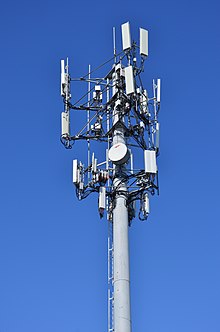
Большая площадь населенной части нашей страны покрыта Базовыми Станциями (БС). В поле они выглядят как красно-белые вышки, а в городе спрятаны на крышах нежилых домов. Каждая станция ловит сигнал от мобильных телефонов на удалении до 35 километров и общается с мобильным телефоном по служебным или голосовым каналам.

После того, как вы набрали номер друга, ваш телефон связывается с ближайшей к вам Базовой Станцией (БС) по служебному каналу и просит выделить голосовой канал. Базовая Станция отправляет запрос на контроллер (BSC), а тот переадресует его на коммутатор (MSC). Если ваш друг является абонентом той же сотовой сети, то коммутатор сверится с Home Location Register (HLR), выяснит, где в данный момент находится вызываемый абонент (дома, в Турции или на Аляске), и переведет звонок на соответствующий коммутатор, откуда тот его переправит на контроллер и затем на Базовую Станцию. Базовая Станция свяжется с мобильным телефоном и соединит вас с другом. Если ваш друг абонент другой сети или вы звоните на городской телефон, то ваш коммутатор обратится к соответствующему коммутатору другой сети. Сложно? Давайте разберемся подробнее. Базовая Станция представляет из себя пару железных шкафов, запертых в хорошо кондиционируемом помещении. Учитывая, что в Москве было на улице +40, мне захотелось немного пожить в этом помещении. Обычно, Базовая Станция находится либо на чердаке здания, либо в контейнере на крыше:
2. 
Антенна Базовой Станции разделена на несколько секторов, каждый из которых «светит» в свою сторону. Вертикальная антенна осуществляет связь с телефонами, круглая соединяет Базовую Станцию с контроллером:
3. 
Каждый сектор может обслуживать до 72 звонков одновременно, в зависимости от настройки и конфигурации. Базовая Станция может состоять из 6 секторов, таким образом, одна Базовая Станция может обслуживать до 432 звонков, однако, обычно на станции установлено меньшее количество передатчиков и секторов. Сотовые операторы предпочитают ставить больше БС для улучшения качества связи. Базовая Станция может работать в трех диапазонах: 900 МГц — сигнал на этой частоте распространяется дальше и лучше проникает внутрь зданий 1800 МГц — сигнал распространяется на более короткие расстояния, но позволяет установить большее количество передатчиков на 1 секторе 2100 МГц — Сеть 3G Вот так выглядит шкаф с 3G оборудованием:
4. 
На Базовые Станции в полях и деревнях устанавливают передатчики 900 МГц, а в городе, где Базовые Станции натыканы как иглы у ежика, в основном, связь осуществляется на частоте 1800 МГц, хотя на любой Базовой Станции могут присутствовать передатчики всех трех диапазонов одновременно.
5. 
6. 
Сигнал частотой 900 МГц может бить до 35 километров, хотя «дальность» некоторых Базовых Станций, стоящих вдоль трасс, может доходить до 70 километров, за счет снижения числа одновременно обслуживаемых абонентов на станции в два раза. Соответственно, наш телефон с его маленькой встроенной антенной также может передавать сигнал на расстояние до 70 километров… Все Базовые Станции проектируются таким образом, чтобы обеспечить оптимальное покрытие радиосигналом на уровне земли. Поэтому, несмотря на дальность в 35 километров, на высоту полета самолетов радиосигнал просто не посылается. Тем не менее, некоторые авиакомпании уже начали устанавливать на своих самолетах маломощные базовые станции, которые обеспечивают покрытие внутри самолета. Такая БС соединяется с наземной сотовой сетью с помощью спутникового канала. Система дополняется панелью управления, которая позволяет экипажу включать и выключать систему, а также отдельные типы услуг, например, выключать голос на ночных рейсах. Телефон может измерять уровень сигнала от 32 Базовых Станций одновременно. Информацию о 6-ти лучших (по уровню сигнала) он отправляет по служебному каналу, и уже контроллер (BSC) решает, какой БС передать текущий звонок (Handover), если вы находитесь в движении. Иногда телефон может ошибиться и перебросить вас на БС с худшим сигналом, в этом случае разговор может прерваться. Также может оказаться, что на Базовой Станции, которую выбрал ваш телефон, все голосовые линии заняты. В этом случае разговор также прервется. Еще мне рассказали о так называемой «проблеме верхних этажей». Если вы живете в пентхаусе, то иногда, при переходе из одной комнаты в другую, разговор может прерываться. Это происходит потому, что в одной комнате телефон может «видеть» одну БС, а во второй — другую, если она выходит на другую сторону дома, и, при этом эти 2 Базовые Станции находятся на большом удалении друг от друга и не прописаны как «соседние» у сотового оператора. В этом случае передача звонка с одной БС на другую происходить не будет:

Связь в метро обеспечивается так же, как и на улице: Базовая Станция – контроллер – коммутатор, с той лишь разницей, что применяются там маленькие Базовые Станции, а в тоннеле покрытие обеспечивается не обычной антенной, а специальным излучающим кабелем. Как я уже писал выше, одна БС может производить до 432 звонков одновременно. Обычно этой мощности хватает за глаза, но, например, во время некоторых праздников БС может не справиться с количеством желающих позвонить. Обычно это случается на Новый Год, когда все начинают поздравлять друг друга. SMS передаются по служебным каналам. На 8 марта и 23 февраля люди предпочитают поздравлять друг друга с помощью SMS, пересылая смешные стишки, и телефоны зачастую не могут договориться с БС о выделении голосового канала. Мне рассказали интересный случай. Из одного района Москвы стали поступать жалобы от абонентов о том, что они не могут никуда дозвониться. Технические специалисты стали разбираться. Большинство голосовых каналов было свободно, а все служебные были заняты. Оказалось, что рядом с этой БС находился институт, в котором шли экзамены и студенты беспрерывно обменивались эсэмэсками. Длинные SMS телефон делит на несколько коротких и отправляет каждое отдельно. Сотрудники технической службы советуют отправлять такие поздравления с помощью MMS. Это будет быстрее и дешевле. С Базовой Станции звонок попадает на контроллер. Выглядит он так же скучно, как и сама БС — это просто набор шкафов:
7. 
В зависимости от оборудования, контроллер может обслуживать до 60 Базовых Станций. Связь между БС и контроллером (BSC) может осуществляться по радиорелейному каналу либо по оптике. Контроллер осуществляет управление работой радиоканалов, в т.ч. контролирует передвижение абонента, передачу сигнала с одной БС на другую. Гораздо интереснее выглядит коммутатор:
8. 
9. 
Каждый коммутатор обслуживает от 2 до 30 контроллеров. Он занимает уже большой зал, заставленный различными шкафами с оборудованием:
10. 
11. 
12. 
Коммутатор осуществляет управление трафиком. Помните старые фильмы, где люди сначала дозванивались до «девушки», а затем она уже соединяла их с другим абонентом, перетыкивая проводки? Этим же занимаются и современные коммутаторы:
13. 
Для контроля за сетью у Билайна есть несколько автомобилей, которые они ласково называют «ежики». Они передвигаются по городу и измеряют уровень сигнала собственной сети, а также уровень сети коллег из «Большой Тройки»:
14. 
Вся крыша такого автомобиля утыкана антеннами:
15. 
Внутри стоит оборудование, осуществляющее сотни звонков и снимающее информацию:
16. 
Круглосуточный контроль за коммутаторами и контроллерами осуществляется из Центра Управления Полетами Центра Контроля Сети (ЦКС):
17. 
Существует 3 основных направления по контролю за сотовой сетью: аварийность, статистика и обратная связь от абонентов. Так же, как и в самолетах, на всем оборудовании сотовой сети стоят датчики, которые посылают сигнал в ЦКС и выводят информацию на компьютеры диспетчеров. Если какое-то оборудование вышло из строя, то на мониторе начнет «мигать лампочка». ЦКС также отслеживает статистику по всем коммутаторам и контроллерам. Он анализирует ее, сравнивая с предыдущими периодами (часом, сутками, неделей и т.д.). Если статистика какого-то из узлов стала резко отличаться от предыдущих показателей, то на мониторе опять начнет «мигать лампочка». Обратную связь принимают операторы абонентской службы. Если они не могут решить проблему, то звонок переводится на технического специалиста. Если же и он оказывается бессильным, то в компании создается «инцидент», который решают инженеры, занимающиеся эксплуатацией соответствующего оборудования. За коммутаторами круглосуточно следят по 2 инженера:
18. 
На графике показана активность московских коммутаторов. Хорошо видно, что ночью практически никто не звонит:
19. 
Контроль за контроллерами (простите за тавтологию) осуществляется со второго этажа Центра Контроля Сети:
22. 
21. 
Источник
Что такое сотовая связь?
Сотовая связь — разновидность радиосвязи, а значит есть устройство, отправляющее сигнал (например, ваш мобильный) и устройство, принимающее его (например, мобильный вашего друга). Между ними находятся базовые станции, которые ретранслируют сигнал. Чтобы вы могли сохранять непрерывную связь на больших расстояниях, без помех и двигаясь в пространстве, этих станций много. Они размещены так, чтобы их «круги охвата» краями накладывались друг на друга.
Что такое базовая станция?
Этот загадочный объект каждый видел, и неоднократно. Да, те самые сотовые вышки, которые стоят в поле. В крупных городах базовые станции обычно «прячут» на крышах домов. Одна такая станция может обслужить до 432 звонков одновременно.
Так выглядит типичная базовая станция на крыше многоэтажки. Фото: Depositphotos
Почему связь «сотовая»?
Если посмотреть сверху на схему сети базовых станций, то их пересекающиеся краями круги покрытия словно составляют пчелиные соты.
Что показывает значок сети?
Даже когда мы не совершаем звонков, телефон постоянно поддерживает сигнал с базовыми станциями. Принцип связи бывает нескольких разных видов, но суть в том, что поймав сигнал, испускаемый станцией, телефон в ответ отправляет свой идентификационный код, уникальный для каждого. Если обмен проходит штатно, у нас «есть сеть», если нет, связь прерывается.
Что происходит после того, как вы набрали чей-то номер телефона?
Первым делом ваш телефон связывается с базовой станцией. Он посылает ей сигнал, которым просит выделить канал для разговора.
Если сигнал принят, то дальше он обрабатывается контроллером базовой станции (BSC). Он управляет освобождением и сменой разговорных каналов. А от BSC сигнал идет на коммутатор.
Если вы представили себе девушек, вручную перетыкающих штекеры соединений, то развидьте. Коммутатор автоматически ищет другой коммутатор, максимально близко расположенный к адресату вашего звонка. Для начала он проверяет, вашего адресата: он из вашей сотовой сети, или абонент другого оператора? Если операторы разные, ваш коммутатор радостно «сваливает работу» на такой же коммутатор этого самого оператора.
Свой или чужой, главное что в итоге ближайший ко второму абоненту коммутатор передает на контроллер сигнала. А этот BSC через самую ближнюю к адресату звонка базовую станцию выделяет голосовой канал для ответа, и ваш друг слышит, что вы ему звоните.
Изображение: Tеле2
Почему иногда внезапно пропадает связь?
Если телефон исправен, то это как правило либо разрыв в покрытии базовых станций, либо их перегрузка.
Разрыв случается там, где не достает мощности сигнала. Например, в подземном переходе. А еще из-за классического «гладко было на бумаге, да забыли про овраги». Покрытие базовой станции образует круг при условии ровного плоского рельефа. Гора, впадина, балка — и края «сот» разомкнулись, получилась «дырка».
Перегрузка возникает из-за того, что каждая базовая станция обеспечивает ограниченное число каналов связи. Если вы на многотысячном концерте, а местная станция может «поднять» несколько сотен звонков, то будьте уверены: связаться ни с кем нормально не получится.
Это тоже интересно:
Пятница, братья и сестры, а по пятницам у нас подкаст с конспектом. Подкаст «Запуск завтра» выходит при поддержке Практикума, а мы тоже выходим при поддержке Практикума, поэтому синергия. Сегодня говорим об устройстве сотовой связи. Слушайте подкаст, если есть время, а если нет — читайте основные мысли ниже.
О герое
Герой выпуска — Александр Чемерис, сотрудник компании YADRO. Руководил стартапом Fairwaves, где делал оборудование для сотовых операторов, обеспечивал связью африканские деревни и штат Оахака в Мексике.
Как Александр попал в мир сотовой связи
Я начал заниматься сотовой связью через софт. Писал диплом по коммуникациям Voice over IP (VoIP). Это возможность говорить голосом через интернет, например как в Skype или Telegram. Потом появился опенсорсный проект Open BTS, который, с помощью VoIP и железа под названием Software-Defined Radio позволял сделать сотовую станцию. Мы с приятелем подумали: «Это же прикольно!». Купили такую карточку и попробовали это дело запустить. Так я из софта перешёл в сотовую связь.
Оказалось, что сотовая связь — это отдельный мир, который можно изучать годами. Ты в него погружаешься, а потом раз — и десять лет прошло.
Как устроена сотовая связь
Она работает на радиоволнах. Вот как мы голосом говорим — и голос распространяется по воздуху на расстоянии. У радиоволн похожий принцип, но распространяются они гораздо дальше, воздух им не мешает. Ушами мы радиоволны слышать не можем, но в телефонах есть специальные антенны, которые умеют воспринимать эти колебания.
Почему по сотовому мы можем говорить одновременно
ТВ-вещание либо радиовещание — это симплексная связь, то есть односторонняя. Один источник сигнала облучает какую-то местность, и все приёмники в этой местности «слышат» этот сигнал.
Сотовая связь — это дуплексная связь, двусторонняя. В сотовой связи есть «канал вверх» и «канал вниз», они так и называются — uplink и downlink. Вниз — это канал к абоненту, потому что вышка обычно выше него, а вверх, соответственно, от абонента туда, наверх, в сторону вышки.
Два самых популярных способа разделения — это frequency division duplex и time division duplex, FDD и TDD соответственно. Классическая сотовая связь построена на FDD, когда у тебя на одной частоте телефон принимает, а на другой передаёт. То есть у тебя словно два радио на разных частотах: по одному ты передаёшь сигнал, по другому — передаёт вышка.
TDD — это то, что мы сейчас делаем. Пока я говорю, ты молчишь, когда ты говоришь, я молчу. Когда все начинают говорить одновременно, происходит интерференция — становится плохо слышно, у тебя начинает квакать телефон.
Стандартный TDD в сотовой связи построен на фреймах, где длина одного фрейма в 4G — 10 миллисекунд, в 5G — до одной миллисекунды. Дальше 10 миллисекунд разбиваются на uplink и downlink, ты 5 миллисекунд говоришь и 5 миллисекунд слушаешь. Это настолько мало, что тебе кажется: ты в любой момент можешь начать говорить, не надо ждать собеседника.
Какие железки отвечают за передачу сигнала
Исключая абонентские устройства, сеть состоит из трёх компонентов: софт у оператора, базовые станции на вышках и связь между ними — транспортная сеть, или бэкхолл.
Вышка обычно подключена к мощному источнику электроэнергии. У неё большие антенны, которые усиливают сигнал. Ты физически не можешь носить телефон, у которого антенна два метра, поэтому антенна на вышке всегда большая. Если сравнить мощность излучения, то у телефона она намного меньше, чем у вышки. Это отчасти связано с какими-то медицинскими нормами, но на самом деле просто экономически невыгодно делать телефон, который будет передавать мощный сигнал: у него будет быстро садиться батарейка.
Роль вышки — передать и принять сигнал с телефона. Причём сделать это качественно и так, чтобы телефон садился не за два часа, а за пару дней хотя бы. Вышка — это физическое устройство, которое ты видишь на улице, а есть базовая станция — это то, что находится на вышке. Если поставить одну такую базовую станцию в центре деревни, то у всех людей нормально будут работать телефоны, которые находятся в зоне доступа. А если навтыкать вышки рядом друг с другом, то начнутся проблемы со связью.
Почему сеть называется «сотовая»
Потому что у тебя вышки натыканы как медовые соты, а вокруг базовой станции зона приёма словно шестиугольник.
Есть целая наука и отдельные люди, которые занимаются радиопланированием. Они делают, так чтобы базовые станции друг другу не мешали и всё это хорошо работало. Говоря математически, если у тебя сотовые вышки передают с одинаковой мощностью, то оптимальное распределение этих вышек будет такое, что каждая стоит в центре шестиугольника. Если ты построишь изолинии равной мощности, то там, где мощность одной вышки падает настолько, что мощность второй вышки начинает вырастать, ты увидишь, что изолинии образуют шестиугольник. Это действительно так физически устроено и выглядит как соты.
Сейчас всё сложнее. Появились макростанции, пикостанции, маленькие станции, зонтичные станции, фемтостанции, которые можно дома поставить.
«Прогресс дошёл до того, что базовые станции учатся договариваться между собой, кто когда передаёт. Условно говоря, маленькая базовая станция, фемтосота, у тебя в квартире в какой-то момент может сказать большой сотовой станции, которая стоит за окном: „Слушай, я буду передавать вот в такое время, вот на такой частоте, ты помолчи. В мою сторону не свети, я тут сейчас дело сделаю, а потом продолжишь“».
Кому принадлежат вышки
Не хочу углубляться в эту тему, это целая отдельная индустрия башенных компаний. Они продают то, что по-английски называется vertical real estate. По-русски это будет «вертикальная жилплощадь». Есть целое понятие — BTS Hotel, то есть отель базовых станций. Ставишь такую вышку, а дальше сдаёшь в ней номера.
В России по закону базовая станция должна принадлежать мобильному оператору, иначе её не разрешат вывести в эфир. Но бывает и по-другому. Например, Tinkoff Mobile — это виртуальный мобильный оператор. У него есть бренд, но нет своих базовых станций, то есть он с кем-то договорился. А настоящий мобильный оператор — это компания, которая владеет лицензией на частоты. Диапазон частот делится на маленькие кусочки и продаётся по частям за бешеные деньги разным операторам связи.
«В связи с появлением 5G в Америке был крупный аукцион, где платили десятки миллиардов долларов за право работать на определённых частотах. В России аукцион частот — такой же способ заработать денег для государства. Можно собирать налоги, а можно продавать частоты».
Кто помимо государства в России владеет частотами
Из федеральных операторов, которые присутствуют в подавляющем большинстве регионов России, «большая четвёрка»: «МегаФон», «МТС», «Билайн» — он же VEON, и «Ростелеком» — он же «Теле2». Осталось несколько мелких региональных операторов, остальных выкупили крупные московские и питерские компании.
В чём отличие 1G от 5G
G — это Generation, «поколение». Новое поколение сотовой связи появляется примерно раз в десять лет. Нужно всё стандартизировать, изготовить оборудование, развернуть его и получить частоты. Это длительная процедура.
Сеть 1G появилась в 1979 году. Главная инновация была в том самом подходе, когда вышки ставятся по сотовому принципу. Сеть второго поколения 2G — это переход к цифровым коммуникациям, что позволило повысить ёмкость и безопасность. Повысилось количество абонентов и стало невозможно при помощи аудиоприёмника подслушать, о чём люди говорят по телефону.
Сеть третьего поколения научилась нормально передавать интернет. Без 3G не было бы iPhone с его приложениями. 4G изначально задумывалась для интернета, а не для голоса. До сих пор во многих сетях 4G ты не можешь поговорить голосом. С этим помогает LTE — конкретная реализация голосовой связи, которая стала доминирующей.
В 2019 году начали появляться самые первые 5G — это попытка улучшить 4G, подстроить под промышленные юзкейсы.
Первый юзкейс Massive IoT — условно, 10 тысяч устройств на квадратный километр. Используется на заводе, который обвешан датчиками. Второй юзкейс — Ultra Reliable Low Latency Communications. Это управление робототехникой, телемедицина, удалённое управление поездами, гейминг. Третье — это то, что называется Mobile Broadband, более быстрая передача данных.
Как родилась идея для стартапа
Люди на какой-нибудь шахте либо на нефтяной вышке тоже хотят говорить друг с другом по сотовому или, что ещё сложнее, звонить домой. Им нужно дать для этого инструмент. Одна базовая станция на какой-нибудь нефтяной вышке для монстра типа Nokia или Ericsson вообще не важна. Но для небольшой компании, если посчитать, это интересный бизнес-кейс.
Мы работали с легитимными сотовыми операторами. У них есть частоты, но есть проблема с тем, что на оборудовании крупных вендоров им невыгодно идти в деревню. Чтобы сделать связь в таких удалённых регионах, я продавал решение — оборудование и софт. Физически это выглядит как ребристая коробочка около 10 кг размером с небольшой рюкзак. Я её как раз в рюкзаке с собой и таскал на презентации.
Внутри такой базовой станции компьютер и радиокомпоненты. Стоит разъём под большую внешнюю антенну, которую покупаешь отдельно. Антенны бывают разные. Ты выбираешь нужную под ландшафт и местность и затем прикручиваешь к вышке. Дальше прикручиваешь базовую станцию и соединяешь толстым радиокабелем с антенной.
В стандартной африканской деревне вышки с разумными антеннами покрывают радиус 5–7 километров. Это размер небольшого города или деревни. К такой базовой станции можно подключить дешёвую Nokia или даже iPhone.
Почему стартап закрылся
Мы не выдержали гонку с более обеспеченными стартапами. Сначала были богатые TIER 1 и несколько небольших компаний по всему миру. Мы все друг друга знали. С одной стороны, мы всегда соревновались, с другой — были против тех мужиков в костюмах от монополистов.
Потом сработала трамповская война против Китая, которая привела к тому, что начал разваливаться единый телекоммуникационный мир. Индустрия поделилась на национальные анклавы. В Европе остались Ericsson и Nokia. В Штатах появились хорошо профинансированные стартапы. Параллельно такие же процессы начали происходить в Индии. Начали появляться национальные разработчики в Японии и во Вьетнаме.
Мой стартап назывался Fairwaves — «Справедливые волны». Я проработал там практически десять лет. Сейчас мы занимаемся тем же самым, чем занимались раньше, — создаём оборудование для операторов сотовой связи, только теперь не для США, а для России.
В полной версии подкаста
14:00 Как победить интерференцию
18:00 Почему мегагерцы стоят денег
27:00 Как наследственность в сотовой связи сделала её уязвимой
33:10 Что означают все эти G
38:00 Почему, когда говоришь по 4G, интернет виснет
43:42 Как развернуть свою локальную сеть
51:20 Вышка из бамбуковой палки и государственная монополия на связь. Что Саша делал в Мексике
58:30 Почему Саша закрыл стартап
Вёрстка:
Кирилл Климентьев
Top of a cellular radio tower

Indoor cell site in Germany
A cellular network or mobile network is a communication network where the link to and from end nodes is wireless. The network is distributed over land areas called «cells», each served by at least one fixed-location transceiver (typically three cell sites or base transceiver stations). These base stations provide the cell with the network coverage which can be used for transmission of voice, data, and other types of content. A cell typically uses a different set of frequencies from neighboring cells, to avoid interference and provide guaranteed service quality within each cell.[citation needed][1]
When joined together, these cells provide radio coverage over a wide geographic area. This enables numerous portable transceivers (e.g., mobile phones, tablets and laptops equipped with mobile broadband modems, pagers, etc.) to communicate with each other and with fixed transceivers and telephones anywhere in the network, via base stations, even if some of the transceivers are moving through more than one cell during transmission.
Cellular networks offer a number of desirable features:[1]
- More capacity than a single large transmitter, since the same frequency can be used for multiple links as long as they are in different cells
- Mobile devices use less power than with a single transmitter or satellite since the cell towers are closer[2]
- Larger coverage area than a single terrestrial transmitter, since additional cell towers can be added indefinitely and are not limited by the horizon
- Capability of utilizing higher frequency signals (and thus more available bandwidth / faster data rates) that are not able to propagate at long distances
- With data compression and multiplexing, several video (including digital video) and audio channels may travel through a higher frequency signal on a single wideband carrier
Major telecommunications providers have deployed voice and data cellular networks over most of the inhabited land area of Earth. This allows mobile phones and mobile computing devices to be connected to the public switched telephone network and public Internet access. Private cellular networks can be used for research[3] or for large organizations and fleets, such as dispatch for local public safety agencies or a taxicab company.[2] T-Mobile’s mid-band PCS spectrum, which was bolstered when it was allowed to buy Sprint a few years ago.
Concept[edit]

Example of frequency reuse factor or pattern 1/4
In a cellular radio system, a land area to be supplied with radio service is divided into cells in a pattern dependent on terrain and reception characteristics. These cell patterns roughly take the form of regular shapes, such as hexagons, squares, or circles although hexagonal cells are conventional. Each of these cells is assigned with multiple frequencies (f1 – f6) which have corresponding radio base stations. The group of frequencies can be reused in other cells, provided that the same frequencies are not reused in adjacent cells, which would cause co-channel interference.
The increased capacity in a cellular network, compared with a network with a single transmitter, comes from the mobile communication switching system developed by Amos Joel of Bell Labs[4] that permitted multiple callers in a given area to use the same frequency by switching calls to the nearest available cellular tower having that frequency available. This strategy is viable because a given radio frequency can be reused in a different area for an unrelated transmission. In contrast, a single transmitter can only handle one transmission for a given frequency. Inevitably, there is some level of interference from the signal from the other cells which use the same frequency. Consequently, there must be at least one cell gap between cells which reuse the same frequency in a standard frequency-division multiple access (FDMA) system.
Consider the case of a taxi company, where each radio has a manually operated channel selector knob to tune to different frequencies. As drivers move around, they change from channel to channel. The drivers are aware of which frequency approximately covers some area. When they do not receive a signal from the transmitter, they try other channels until finding one that works. The taxi drivers only speak one at a time when invited by the base station operator. This is a form of time-division multiple access (TDMA).
History[edit]
The first commercial cellular network, the 1G generation, was launched in Japan by Nippon Telegraph and Telephone (NTT) in 1979, initially in the metropolitan area of Tokyo. Within five years, the NTT network had been expanded to cover the whole population of Japan and became the first nationwide 1G network. It was an analog wireless network. The Bell System had developed cellular technology since 1947, and had cellular networks in operation in Chicago and Dallas prior to 1979, but commercial service was delayed by the breakup of the Bell System, with cellular assets transferred to the Regional Bell Operating Companies.
The wireless revolution began in the early 1990s,[5][6][7] leading to the transition from analog to digital networks.[8] This was enabled by advances in MOSFET technology. The MOSFET, originally invented by Mohamed M. Atalla and Dawon Kahng at Bell Labs in 1959,[9][10] was adapted for cellular networks by the early 1990s, with the wide adoption of power MOSFET, LDMOS (RF amplifier), and RF CMOS (RF circuit) devices leading to the development and proliferation of digital wireless mobile networks.[8][11][12]
The first commercial digital cellular network, the 2G generation, was launched in 1991. This sparked competition in the sector as the new operators challenged the incumbent 1G analog network operators.
Cell signal encoding[edit]
To distinguish signals from several different transmitters, frequency-division multiple access (FDMA, used by analog and D-AMPS[citation needed] systems), time-division multiple access (TDMA, used by GSM) and code-division multiple access (CDMA, first used for PCS, and the basis of 3G) were developed.[1]
With FDMA, the transmitting and receiving frequencies used by different users in each cell are different from each other. Each cellular call was assigned a pair of frequencies (one for base to mobile, the other for mobile to base) to provide full-duplex operation. The original AMPS systems had 666 channel pairs, 333 each for the CLEC «A» system and ILEC «B» system. The number of channels was expanded to 416 pairs per carrier, but ultimately the number of RF channels limits the number of calls that a cell site could handle. Note that FDMA is a familiar technology to telephone companies, that used frequency-division multiplexing to add channels to their point-to-point wireline plants before time-division multiplexing rendered FDM obsolete.
With TDMA, the transmitting and receiving time slots used by different users in each cell are different from each other. TDMA typically uses digital signaling to store and forward bursts of voice data that are fit into time slices for transmission, and expanded at the receiving end to produce a somewhat normal-sounding voice at the receiver. TDMA must introduce latency (time delay) into the audio signal. As long as the latency time is short enough that the delayed audio is not heard as an echo, it is not problematic. Note that TDMA is a familiar technology for telephone companies, that used time-division multiplexing to add channels to their point-to-point wireline plants before packet switching rendered FDM obsolete.
The principle of CDMA is based on spread spectrum technology developed for military use during World War II and improved during the Cold War into direct-sequence spread spectrum that was used for early CDMA cellular systems and Wi-Fi. DSSS allows multiple simultaneous phone conversations to take place on a single wideband RF channel, without needing to channelize them in time or frequency. Although more sophisticated than older multiple access schemes (and unfamiliar to legacy telephone companies because it was not developed by Bell Labs), CDMA has scaled well to become the basis for 3G cellular radio systems.
Other available methods of multiplexing such as MIMO, a more sophisticated version of antenna diversity, combined with active beamforming provides much greater spatial multiplexing ability compared to original AMPS cells, that typically only addressed one to three unique spaces. Massive MIMO deployment allows much greater channel re-use, thus increasing the number of subscribers per cell site, greater data throughput per user, or some combination thereof. Quadrature Amplitude Modulation (QAM) modems offer an increasing number of bits per symbol, allowing more users per megahertz of bandwidth (and decibels of SNR), greater data throughput per user, or some combination thereof.
Frequency reuse[edit]
The key characteristic of a cellular network is the ability to re-use frequencies to increase both coverage and capacity. As described above, adjacent cells must use different frequencies, however, there is no problem with two cells sufficiently far apart operating on the same frequency, provided the masts and cellular network users’ equipment do not transmit with too much power.[1]
The elements that determine frequency reuse are the reuse distance and the reuse factor. The reuse distance, D is calculated as
,
where R is the cell radius and N is the number of cells per cluster. Cells may vary in radius from 1 to 30 kilometres (0.62 to 18.64 mi). The boundaries of the cells can also overlap between adjacent cells and large cells can be divided into smaller cells.[13]
The frequency reuse factor is the rate at which the same frequency can be used in the network. It is 1/K (or K according to some books) where K is the number of cells which cannot use the same frequencies for transmission. Common values for the frequency reuse factor are 1/3, 1/4, 1/7, 1/9 and 1/12 (or 3, 4, 7, 9 and 12 depending on notation).[14]
In case of N sector antennas on the same base station site, each with different direction, the base station site can serve N different sectors. N is typically 3. A reuse pattern of N/K denotes a further division in frequency among N sector antennas per site. Some current and historical reuse patterns are 3/7 (North American AMPS), 6/4 (Motorola NAMPS), and 3/4 (GSM).
If the total available bandwidth is B, each cell can only use a number of frequency channels corresponding to a bandwidth of B/K, and each sector can use a bandwidth of B/NK.
Code-division multiple access-based systems use a wider frequency band to achieve the same rate of transmission as FDMA, but this is compensated for by the ability to use a frequency reuse factor of 1, for example using a reuse pattern of 1/1. In other words, adjacent base station sites use the same frequencies, and the different base stations and users are separated by codes rather than frequencies. While N is shown as 1 in this example, that does not mean the CDMA cell has only one sector, but rather that the entire cell bandwidth is also available to each sector individually.
Recently also orthogonal frequency-division multiple access based systems such as LTE are being deployed with a frequency reuse of 1. Since such systems do not spread the signal across the frequency band,
inter-cell radio resource management is important to coordinate resource allocation between different cell sites and to limit the inter-cell interference. There are various means of inter-cell interference coordination (ICIC) already defined in the standard.[15] Coordinated scheduling, multi-site MIMO or multi-site beamforming are other examples for inter-cell radio resource management that might be standardized in the future.
Directional antennas[edit]

Cell towers frequently use a directional signal to improve reception in higher-traffic areas. In the United States, the Federal Communications Commission (FCC) limits omnidirectional cell tower signals to 100 watts of power. If the tower has directional antennas, the FCC allows the cell operator to emit up to 500 watts of effective radiated power (ERP).[16]
Although the original cell towers created an even, omnidirectional signal, were at the centers of the cells and were omnidirectional, a cellular map can be redrawn with the cellular telephone towers located at the corners of the hexagons where three cells converge.[17] Each tower has three sets of directional antennas aimed in three different directions with 120 degrees for each cell (totaling 360 degrees) and receiving/transmitting into three different cells at different frequencies. This provides a minimum of three channels, and three towers for each cell and greatly increases the chances of receiving a usable signal from at least one direction.
The numbers in the illustration are channel numbers, which repeat every 3 cells. Large cells can be subdivided into smaller cells for high volume areas.[18]
Cell phone companies also use this directional signal to improve reception along highways and inside buildings like stadiums and arenas.[16]
Broadcast messages and paging[edit]
Practically every cellular system has some kind of broadcast mechanism. This can be used directly for distributing information to multiple mobiles. Commonly, for example in mobile telephony systems, the most important use of broadcast information is to set up channels for one-to-one communication between the mobile transceiver and the base station. This is called paging. The three different paging procedures generally adopted are sequential, parallel and selective paging.
The details of the process of paging vary somewhat from network to network, but normally we know a limited number of cells where the phone is located (this group of cells is called a Location Area in the GSM or UMTS system, or Routing Area if a data packet session is involved; in LTE, cells are grouped into Tracking Areas). Paging takes place by sending the broadcast message to all of those cells. Paging messages can be used for information transfer. This happens in pagers, in CDMA systems for sending SMS messages, and in the UMTS system where it allows for low downlink latency in packet-based connections.
Movement from cell to cell and handing over[edit]
In a primitive taxi system, when the taxi moved away from a first tower and closer to a second tower, the taxi driver manually switched from one frequency to another as needed. If communication was interrupted due to a loss of a signal, the taxi driver asked the base station operator to repeat the message on a different frequency.
In a cellular system, as the distributed mobile transceivers move from cell to cell during an ongoing continuous communication, switching from one cell frequency to a different cell frequency is done electronically without interruption and without a base station operator or manual switching. This is called the handover or handoff. Typically, a new channel is automatically selected for the mobile unit on the new base station which will serve it. The mobile unit then automatically switches from the current channel to the new channel and communication continues.
The exact details of the mobile system’s move from one base station to the other vary considerably from system to system (see the example below for how a mobile phone network manages handover).
Mobile phone network[edit]

WCDMA network architecture
The most common example of a cellular network is a mobile phone (cell phone) network. A mobile phone is a portable telephone which receives or makes calls through a cell site (base station) or transmitting tower. Radio waves are used to transfer signals to and from the cell phone.
Modern mobile phone networks use cells because radio frequencies are a limited, shared resource. Cell-sites and handsets change frequency under computer control and use low power transmitters so that the usually limited number of radio frequencies can be simultaneously used by many callers with less interference.
A cellular network is used by the mobile phone operator to achieve both coverage and capacity for their subscribers. Large geographic areas are split into smaller cells to avoid line-of-sight signal loss and to support a large number of active phones in that area. All of the cell sites are connected to telephone exchanges (or switches), which in turn connect to the public telephone network.
In cities, each cell site may have a range of up to approximately 1⁄2 mile (0.80 km), while in rural areas, the range could be as much as 5 miles (8.0 km). It is possible that in clear open areas, a user may receive signals from a cell site 25 miles (40 km) away. In rural areas with low-band coverage and tall towers, basic voice and messaging service may reach 50 miles (80 km), with limitations on bandwidth and number of simultaneous calls.[citation needed]
Since almost all mobile phones use cellular technology, including GSM, CDMA, and AMPS (analog), the term «cell phone» is in some regions, notably the US, used interchangeably with «mobile phone». However, satellite phones are mobile phones that do not communicate directly with a ground-based cellular tower but may do so indirectly by way of a satellite.
There are a number of different digital cellular technologies, including: Global System for Mobile Communications (GSM), General Packet Radio Service (GPRS), cdmaOne, CDMA2000, Evolution-Data Optimized (EV-DO), Enhanced Data Rates for GSM Evolution (EDGE), Universal Mobile Telecommunications System (UMTS), Digital Enhanced Cordless Telecommunications (DECT), Digital AMPS (IS-136/TDMA), and Integrated Digital Enhanced Network (iDEN). The transition from existing analog to the digital standard followed a very different path in Europe and the US.[19] As a consequence, multiple digital standards surfaced in the US, while Europe and many countries converged towards the GSM standard.
Structure of the mobile phone cellular network[edit]
A simple view of the cellular mobile-radio network consists of the following:
- A network of radio base stations forming the base station subsystem.
- The core circuit switched network for handling voice calls and text
- A packet switched network for handling mobile data
- The public switched telephone network to connect subscribers to the wider telephony network
This network is the foundation of the GSM system network. There are many functions that are performed by this network in order to make sure customers get the desired service including mobility management, registration, call set-up, and handover.
Any phone connects to the network via an RBS (Radio Base Station) at a corner of the corresponding cell which in turn connects to the Mobile switching center (MSC). The MSC provides a connection to the public switched telephone network (PSTN). The link from a phone to the RBS is called an uplink while the other way is termed downlink.
Radio channels effectively use the transmission medium through the use of the following multiplexing and access schemes: frequency-division multiple access (FDMA), time-division multiple access (TDMA), code-division multiple access (CDMA), and space-division multiple access (SDMA).
Small cells[edit]
Small cells, which have a smaller coverage area than base stations, are categorised as follows:
- Microcell -> less than 2 kilometres,
- Picocell -> less than 200 metres,
- Femtocell -> around 10 metres,
- Attocell -> 1–4 metres
Cellular handover in mobile phone networks[edit]
As the phone user moves from one cell area to another cell while a call is in progress, the mobile station will search for a new channel to attach to in order not to drop the call. Once a new channel is found, the network will command the mobile unit to switch to the new channel and at the same time switch the call onto the new channel.
With CDMA, multiple CDMA handsets share a specific radio channel. The signals are separated by using a pseudonoise code (PN code) that is specific to each phone. As the user moves from one cell to another, the handset sets up radio links with multiple cell sites (or sectors of the same site) simultaneously. This is known as «soft handoff» because, unlike with traditional cellular technology, there is no one defined point where the phone switches to the new cell.
In IS-95 inter-frequency handovers and older analog systems such as NMT it will typically be impossible to test the target channel directly while communicating. In this case, other techniques have to be used such as pilot beacons in IS-95. This means that there is almost always a brief break in the communication while searching for the new channel followed by the risk of an unexpected return to the old channel.
If there is no ongoing communication or the communication can be interrupted, it is possible for the mobile unit to spontaneously move from one cell to another and then notify the base station with the strongest signal.
Cellular frequency choice in mobile phone networks[edit]
The effect of frequency on cell coverage means that different frequencies serve better for different uses. Low frequencies, such as 450 MHz NMT, serve very well for countryside coverage. GSM 900 (900 MHz) is suitable for light urban coverage. GSM 1800 (1.8 GHz) starts to be limited by structural walls. UMTS, at 2.1 GHz is quite similar in coverage to GSM 1800.
Higher frequencies are a disadvantage when it comes to coverage, but it is a decided advantage when it comes to capacity. Picocells, covering e.g. one floor of a building, become possible, and the same frequency can be used for cells which are practically neighbors.
Cell service area may also vary due to interference from transmitting systems, both within and around that cell. This is true especially in CDMA based systems. The receiver requires a certain signal-to-noise ratio, and the transmitter should not send with too high transmission power in view to not cause interference with other transmitters. As the receiver moves away from the transmitter, the power received decreases, so the power control algorithm of the transmitter increases the power it transmits to restore the level of received power. As the interference (noise) rises above the received power from the transmitter, and the power of the transmitter cannot be increased anymore, the signal becomes corrupted and eventually unusable. In CDMA-based systems, the effect of interference from other mobile transmitters in the same cell on coverage area is very marked and has a special name, cell breathing.
One can see examples of cell coverage by studying some of the coverage maps provided by real operators on their web sites or by looking at independently crowdsourced maps such as Opensignal or CellMapper. In certain cases they may mark the site of the transmitter; in others, it can be calculated by working out the point of strongest coverage.
A cellular repeater is used to extend cell coverage into larger areas. They range from wideband repeaters for consumer use in homes and offices to smart or digital repeaters for industrial needs.
Cell size[edit]
The following table shows the dependency of the coverage area of one cell on the frequency of a CDMA2000 network:[20]
| Frequency (MHz) | Cell radius (km) | Cell area (km2) | Relative cell count |
|---|---|---|---|
| 450 | 48.9 | 7521 | 1 |
| 950 | 26.9 | 2269 | 3.3 |
| 1800 | 14.0 | 618 | 12.2 |
| 2100 | 12.0 | 449 | 16.2 |
See also[edit]

Cellular network standards and generation timeline.
Lists and technical information:
- Mobile technologies
- 2G networks (the first digital networks, 1G and 0G were analog):
- GSM
- Circuit Switched Data (CSD)
- GPRS
- EDGE(IMT-SC)
- Evolved EDGE
- Digital AMPS
- Cellular Digital Packet Data (CDPD)
- cdmaOne (IS-95)
- Circuit Switched Data (CSD)
- GSM
- 3G networks:
- UMTS
- W-CDMA (air interface)
- TD-CDMA (air interface)
- TD-SCDMA (air interface)
- HSPA
- HSDPA
- HSPA+
- CDMA2000
- OFDMA (air interface)
- EVDO
- SVDO
- EVDO
- OFDMA (air interface)
- UMTS
- 4G networks:
- LTE (TD-LTE)
- LTE Advanced
- LTE Advanced Pro
- WiMAX
- WiMAX-Advanced (WirelessMAN-Advanced)
- Ultra Mobile Broadband (never commercialized)
- MBWA (IEEE 802.20, Mobile Broadband Wireless Access, HC-SDMA, iBurst, has been shut down)
- LTE (TD-LTE)
- 5G networks:
- 5G NR
- 5G-Advanced
- 2G networks (the first digital networks, 1G and 0G were analog):
Starting with EVDO the following techniques can also be used to improve performance:
- MIMO, SDMA and Beamforming
- Cellular frequencies
- CDMA frequency bands
- GSM frequency bands
- UMTS frequency bands
- LTE frequency bands
- 5G NR frequency bands
- Deployed networks by technology
- List of UMTS networks
- List of CDMA2000 networks
- List of LTE networks
- List of deployed WiMAX networks
- List of 5G NR networks
- Deployed networks by country (including technology and frequencies)
- List of mobile network operators of Europe
- List of mobile network operators of the Americas
- List of mobile network operators of the Asia Pacific region
- List of mobile network operators of the Middle East and Africa
- List of mobile network operators (summary)
- Mobile country code — code, frequency, and technology for each operator in each country
- Comparison of mobile phone standards
Equipment:
- Cellular repeater
- Cellular router
- Professional mobile radio (PMR)
- OpenBTS
Other:
- Cellular traffic
- MIMO (multiple-input and multiple-output)
- Mobile edge computing
- Mobile phone radiation and health
- Network simulation
- Radio resource management (RRM)
- Routing in cellular networks
- Signal strength
- Title 47 of the Code of Federal Regulations
References[edit]
- ^ a b c d Guowang Miao; Jens Zander; Ki Won Sung; Ben Slimane (2016). Fundamentals of Mobile Data Networks. Cambridge University Press. ISBN 978-1107143210.
- ^ a b «Be Mobile, Stay Connected | PMN». Privatemobilenetworks.com. Retrieved 23 November 2013.
- ^ Tom Simonite (24 January 2013). «Google’s Private Cell Phone Network Could Be a Threat to Cellular Carriers | MIT Technology Review». Technologyreview.com. Retrieved 23 November 2013.
- ^ U.S. Patent 3,663,762, issued 16 May 1972.
- ^ Golio, Mike; Golio, Janet (2018). RF and Microwave Passive and Active Technologies. CRC Press. pp. ix, I-1, 18–2. ISBN 9781420006728.
- ^ Rappaport, T. S. (November 1991). «The wireless revolution». IEEE Communications Magazine. 29 (11): 52–71. doi:10.1109/35.109666. S2CID 46573735.
- ^ «The wireless revolution». The Economist. 21 January 1999. Retrieved 12 September 2019.
- ^ a b Baliga, B. Jayant (2005). Silicon RF Power MOSFETS. World Scientific. ISBN 9789812561213.
- ^ Sahay, Shubham; Kumar, Mamidala Jagadesh (2019). Junctionless Field-Effect Transistors: Design, Modeling, and Simulation. John Wiley & Sons. ISBN 9781119523536.
- ^ «Remarks by Director Iancu at the 2019 International Intellectual Property Conference». United States Patent and Trademark Office. 10 June 2019. Archived from the original on 17 December 2019. Retrieved 20 July 2019.
- ^ Asif, Saad (2018). 5G Mobile Communications: Concepts and Technologies. CRC Press. pp. 128–134. ISBN 9780429881343.
- ^ O’Neill, A. (2008). «Asad Abidi Recognized for Work in RF-CMOS». IEEE Solid-State Circuits Society Newsletter. 13 (1): 57–58. doi:10.1109/N-SSC.2008.4785694. ISSN 1098-4232.
- ^ J. E. Flood. Telecommunication Networks. Institution of Electrical Engineers, London, UK, 1997. chapter 12.
- ^ «Phone Networks». The Reverse Phone. 8 June 2011. Archived from the original on 30 April 2012. Retrieved 2 April 2012.
- ^ Pauli, Volker; Naranjo, Juan Diego; Seidel, Eiko (December 2010). «Heterogeneous LTE Networks and Inter-Cell Interference Coordination» (PDF). Nomor Research. Archived from the original (PDF) on 3 September 2013. Retrieved 2 April 2012.
- ^ a b Drucker, Elliott, The Myth of Cellular Tower Health Hazards, archived from the original on 2 May 2014, retrieved 19 November 2013
- ^ «Cellular Telephone Basics». Privateline.com. 1 January 2006. p. 2. Archived from the original on 17 April 2012. Retrieved 2 April 2012.
- ^ U.S. Patent 4,144,411 – Cellular Radiotelephone System for Different Cell Sizes – Richard H. Frenkiel (Bell Labs), filed 22 September 1976, issued 13 March 1979
- ^ Paetsch, Michael (1993): The evolution of mobile communications in the US and Europe. Regulation, technology, and markets. Boston, London: Artech House (The Artech House mobile communications library).
- ^ Colin Chandler (3 December 2003). «CDMA 2000 and CDMA 450» (PDF). p. 17.
Further reading[edit]
- P. Key, D. Smith. Teletraffic Engineering in a competitive world. Elsevier Science B.V., Amsterdam Netherlands, 1999. ISBN 978-0444502681. Chapter 1 (Plenary) and 3 (mobile).
- William C. Y. Lee, Mobile Cellular Telecommunications Systems (1989), McGraw-Hill.
External links[edit]
- Raciti, Robert C. (July 1995). «CELLULAR TECHNOLOGY». Nova Southeastern University. Archived from the original on 15 July 2013. Retrieved 2 April 2012.
- A History of Cellular Networks
- What are cellular networks? 1G to 6G Features & Evolution
Top of a cellular radio tower
Indoor cell site in Germany
A cellular network or mobile network is a communication network where the link to and from end nodes is wireless. The network is distributed over land areas called «cells», each served by at least one fixed-location transceiver (typically three cell sites or base transceiver stations). These base stations provide the cell with the network coverage which can be used for transmission of voice, data, and other types of content. A cell typically uses a different set of frequencies from neighboring cells, to avoid interference and provide guaranteed service quality within each cell.[citation needed][1]
When joined together, these cells provide radio coverage over a wide geographic area. This enables numerous portable transceivers (e.g., mobile phones, tablets and laptops equipped with mobile broadband modems, pagers, etc.) to communicate with each other and with fixed transceivers and telephones anywhere in the network, via base stations, even if some of the transceivers are moving through more than one cell during transmission.
Cellular networks offer a number of desirable features:[1]
- More capacity than a single large transmitter, since the same frequency can be used for multiple links as long as they are in different cells
- Mobile devices use less power than with a single transmitter or satellite since the cell towers are closer[2]
- Larger coverage area than a single terrestrial transmitter, since additional cell towers can be added indefinitely and are not limited by the horizon
- Capability of utilizing higher frequency signals (and thus more available bandwidth / faster data rates) that are not able to propagate at long distances
- With data compression and multiplexing, several video (including digital video) and audio channels may travel through a higher frequency signal on a single wideband carrier
Major telecommunications providers have deployed voice and data cellular networks over most of the inhabited land area of Earth. This allows mobile phones and mobile computing devices to be connected to the public switched telephone network and public Internet access. Private cellular networks can be used for research[3] or for large organizations and fleets, such as dispatch for local public safety agencies or a taxicab company.[2] T-Mobile’s mid-band PCS spectrum, which was bolstered when it was allowed to buy Sprint a few years ago.
Concept[edit]
Example of frequency reuse factor or pattern 1/4
In a cellular radio system, a land area to be supplied with radio service is divided into cells in a pattern dependent on terrain and reception characteristics. These cell patterns roughly take the form of regular shapes, such as hexagons, squares, or circles although hexagonal cells are conventional. Each of these cells is assigned with multiple frequencies (f1 – f6) which have corresponding radio base stations. The group of frequencies can be reused in other cells, provided that the same frequencies are not reused in adjacent cells, which would cause co-channel interference.
The increased capacity in a cellular network, compared with a network with a single transmitter, comes from the mobile communication switching system developed by Amos Joel of Bell Labs[4] that permitted multiple callers in a given area to use the same frequency by switching calls to the nearest available cellular tower having that frequency available. This strategy is viable because a given radio frequency can be reused in a different area for an unrelated transmission. In contrast, a single transmitter can only handle one transmission for a given frequency. Inevitably, there is some level of interference from the signal from the other cells which use the same frequency. Consequently, there must be at least one cell gap between cells which reuse the same frequency in a standard frequency-division multiple access (FDMA) system.
Consider the case of a taxi company, where each radio has a manually operated channel selector knob to tune to different frequencies. As drivers move around, they change from channel to channel. The drivers are aware of which frequency approximately covers some area. When they do not receive a signal from the transmitter, they try other channels until finding one that works. The taxi drivers only speak one at a time when invited by the base station operator. This is a form of time-division multiple access (TDMA).
History[edit]
The first commercial cellular network, the 1G generation, was launched in Japan by Nippon Telegraph and Telephone (NTT) in 1979, initially in the metropolitan area of Tokyo. Within five years, the NTT network had been expanded to cover the whole population of Japan and became the first nationwide 1G network. It was an analog wireless network. The Bell System had developed cellular technology since 1947, and had cellular networks in operation in Chicago and Dallas prior to 1979, but commercial service was delayed by the breakup of the Bell System, with cellular assets transferred to the Regional Bell Operating Companies.
The wireless revolution began in the early 1990s,[5][6][7] leading to the transition from analog to digital networks.[8] This was enabled by advances in MOSFET technology. The MOSFET, originally invented by Mohamed M. Atalla and Dawon Kahng at Bell Labs in 1959,[9][10] was adapted for cellular networks by the early 1990s, with the wide adoption of power MOSFET, LDMOS (RF amplifier), and RF CMOS (RF circuit) devices leading to the development and proliferation of digital wireless mobile networks.[8][11][12]
The first commercial digital cellular network, the 2G generation, was launched in 1991. This sparked competition in the sector as the new operators challenged the incumbent 1G analog network operators.
Cell signal encoding[edit]
To distinguish signals from several different transmitters, frequency-division multiple access (FDMA, used by analog and D-AMPS[citation needed] systems), time-division multiple access (TDMA, used by GSM) and code-division multiple access (CDMA, first used for PCS, and the basis of 3G) were developed.[1]
With FDMA, the transmitting and receiving frequencies used by different users in each cell are different from each other. Each cellular call was assigned a pair of frequencies (one for base to mobile, the other for mobile to base) to provide full-duplex operation. The original AMPS systems had 666 channel pairs, 333 each for the CLEC «A» system and ILEC «B» system. The number of channels was expanded to 416 pairs per carrier, but ultimately the number of RF channels limits the number of calls that a cell site could handle. Note that FDMA is a familiar technology to telephone companies, that used frequency-division multiplexing to add channels to their point-to-point wireline plants before time-division multiplexing rendered FDM obsolete.
With TDMA, the transmitting and receiving time slots used by different users in each cell are different from each other. TDMA typically uses digital signaling to store and forward bursts of voice data that are fit into time slices for transmission, and expanded at the receiving end to produce a somewhat normal-sounding voice at the receiver. TDMA must introduce latency (time delay) into the audio signal. As long as the latency time is short enough that the delayed audio is not heard as an echo, it is not problematic. Note that TDMA is a familiar technology for telephone companies, that used time-division multiplexing to add channels to their point-to-point wireline plants before packet switching rendered FDM obsolete.
The principle of CDMA is based on spread spectrum technology developed for military use during World War II and improved during the Cold War into direct-sequence spread spectrum that was used for early CDMA cellular systems and Wi-Fi. DSSS allows multiple simultaneous phone conversations to take place on a single wideband RF channel, without needing to channelize them in time or frequency. Although more sophisticated than older multiple access schemes (and unfamiliar to legacy telephone companies because it was not developed by Bell Labs), CDMA has scaled well to become the basis for 3G cellular radio systems.
Other available methods of multiplexing such as MIMO, a more sophisticated version of antenna diversity, combined with active beamforming provides much greater spatial multiplexing ability compared to original AMPS cells, that typically only addressed one to three unique spaces. Massive MIMO deployment allows much greater channel re-use, thus increasing the number of subscribers per cell site, greater data throughput per user, or some combination thereof. Quadrature Amplitude Modulation (QAM) modems offer an increasing number of bits per symbol, allowing more users per megahertz of bandwidth (and decibels of SNR), greater data throughput per user, or some combination thereof.
Frequency reuse[edit]
The key characteristic of a cellular network is the ability to re-use frequencies to increase both coverage and capacity. As described above, adjacent cells must use different frequencies, however, there is no problem with two cells sufficiently far apart operating on the same frequency, provided the masts and cellular network users’ equipment do not transmit with too much power.[1]
The elements that determine frequency reuse are the reuse distance and the reuse factor. The reuse distance, D is calculated as
where R is the cell radius and N is the number of cells per cluster. Cells may vary in radius from 1 to 30 kilometres (0.62 to 18.64 mi). The boundaries of the cells can also overlap between adjacent cells and large cells can be divided into smaller cells.[13]
The frequency reuse factor is the rate at which the same frequency can be used in the network. It is 1/K (or K according to some books) where K is the number of cells which cannot use the same frequencies for transmission. Common values for the frequency reuse factor are 1/3, 1/4, 1/7, 1/9 and 1/12 (or 3, 4, 7, 9 and 12 depending on notation).[14]
In case of N sector antennas on the same base station site, each with different direction, the base station site can serve N different sectors. N is typically 3. A reuse pattern of N/K denotes a further division in frequency among N sector antennas per site. Some current and historical reuse patterns are 3/7 (North American AMPS), 6/4 (Motorola NAMPS), and 3/4 (GSM).
If the total available bandwidth is B, each cell can only use a number of frequency channels corresponding to a bandwidth of B/K, and each sector can use a bandwidth of B/NK.
Code-division multiple access-based systems use a wider frequency band to achieve the same rate of transmission as FDMA, but this is compensated for by the ability to use a frequency reuse factor of 1, for example using a reuse pattern of 1/1. In other words, adjacent base station sites use the same frequencies, and the different base stations and users are separated by codes rather than frequencies. While N is shown as 1 in this example, that does not mean the CDMA cell has only one sector, but rather that the entire cell bandwidth is also available to each sector individually.
Recently also orthogonal frequency-division multiple access based systems such as LTE are being deployed with a frequency reuse of 1. Since such systems do not spread the signal across the frequency band,
inter-cell radio resource management is important to coordinate resource allocation between different cell sites and to limit the inter-cell interference. There are various means of inter-cell interference coordination (ICIC) already defined in the standard.[15] Coordinated scheduling, multi-site MIMO or multi-site beamforming are other examples for inter-cell radio resource management that might be standardized in the future.
Directional antennas[edit]
Cell towers frequently use a directional signal to improve reception in higher-traffic areas. In the United States, the Federal Communications Commission (FCC) limits omnidirectional cell tower signals to 100 watts of power. If the tower has directional antennas, the FCC allows the cell operator to emit up to 500 watts of effective radiated power (ERP).[16]
Although the original cell towers created an even, omnidirectional signal, were at the centers of the cells and were omnidirectional, a cellular map can be redrawn with the cellular telephone towers located at the corners of the hexagons where three cells converge.[17] Each tower has three sets of directional antennas aimed in three different directions with 120 degrees for each cell (totaling 360 degrees) and receiving/transmitting into three different cells at different frequencies. This provides a minimum of three channels, and three towers for each cell and greatly increases the chances of receiving a usable signal from at least one direction.
The numbers in the illustration are channel numbers, which repeat every 3 cells. Large cells can be subdivided into smaller cells for high volume areas.[18]
Cell phone companies also use this directional signal to improve reception along highways and inside buildings like stadiums and arenas.[16]
Broadcast messages and paging[edit]
Practically every cellular system has some kind of broadcast mechanism. This can be used directly for distributing information to multiple mobiles. Commonly, for example in mobile telephony systems, the most important use of broadcast information is to set up channels for one-to-one communication between the mobile transceiver and the base station. This is called paging. The three different paging procedures generally adopted are sequential, parallel and selective paging.
The details of the process of paging vary somewhat from network to network, but normally we know a limited number of cells where the phone is located (this group of cells is called a Location Area in the GSM or UMTS system, or Routing Area if a data packet session is involved; in LTE, cells are grouped into Tracking Areas). Paging takes place by sending the broadcast message to all of those cells. Paging messages can be used for information transfer. This happens in pagers, in CDMA systems for sending SMS messages, and in the UMTS system where it allows for low downlink latency in packet-based connections.
Movement from cell to cell and handing over[edit]
In a primitive taxi system, when the taxi moved away from a first tower and closer to a second tower, the taxi driver manually switched from one frequency to another as needed. If communication was interrupted due to a loss of a signal, the taxi driver asked the base station operator to repeat the message on a different frequency.
In a cellular system, as the distributed mobile transceivers move from cell to cell during an ongoing continuous communication, switching from one cell frequency to a different cell frequency is done electronically without interruption and without a base station operator or manual switching. This is called the handover or handoff. Typically, a new channel is automatically selected for the mobile unit on the new base station which will serve it. The mobile unit then automatically switches from the current channel to the new channel and communication continues.
The exact details of the mobile system’s move from one base station to the other vary considerably from system to system (see the example below for how a mobile phone network manages handover).
Mobile phone network[edit]
WCDMA network architecture
The most common example of a cellular network is a mobile phone (cell phone) network. A mobile phone is a portable telephone which receives or makes calls through a cell site (base station) or transmitting tower. Radio waves are used to transfer signals to and from the cell phone.
Modern mobile phone networks use cells because radio frequencies are a limited, shared resource. Cell-sites and handsets change frequency under computer control and use low power transmitters so that the usually limited number of radio frequencies can be simultaneously used by many callers with less interference.
A cellular network is used by the mobile phone operator to achieve both coverage and capacity for their subscribers. Large geographic areas are split into smaller cells to avoid line-of-sight signal loss and to support a large number of active phones in that area. All of the cell sites are connected to telephone exchanges (or switches), which in turn connect to the public telephone network.
In cities, each cell site may have a range of up to approximately 1⁄2 mile (0.80 km), while in rural areas, the range could be as much as 5 miles (8.0 km). It is possible that in clear open areas, a user may receive signals from a cell site 25 miles (40 km) away. In rural areas with low-band coverage and tall towers, basic voice and messaging service may reach 50 miles (80 km), with limitations on bandwidth and number of simultaneous calls.[citation needed]
Since almost all mobile phones use cellular technology, including GSM, CDMA, and AMPS (analog), the term «cell phone» is in some regions, notably the US, used interchangeably with «mobile phone». However, satellite phones are mobile phones that do not communicate directly with a ground-based cellular tower but may do so indirectly by way of a satellite.
There are a number of different digital cellular technologies, including: Global System for Mobile Communications (GSM), General Packet Radio Service (GPRS), cdmaOne, CDMA2000, Evolution-Data Optimized (EV-DO), Enhanced Data Rates for GSM Evolution (EDGE), Universal Mobile Telecommunications System (UMTS), Digital Enhanced Cordless Telecommunications (DECT), Digital AMPS (IS-136/TDMA), and Integrated Digital Enhanced Network (iDEN). The transition from existing analog to the digital standard followed a very different path in Europe and the US.[19] As a consequence, multiple digital standards surfaced in the US, while Europe and many countries converged towards the GSM standard.
Structure of the mobile phone cellular network[edit]
A simple view of the cellular mobile-radio network consists of the following:
- A network of radio base stations forming the base station subsystem.
- The core circuit switched network for handling voice calls and text
- A packet switched network for handling mobile data
- The public switched telephone network to connect subscribers to the wider telephony network
This network is the foundation of the GSM system network. There are many functions that are performed by this network in order to make sure customers get the desired service including mobility management, registration, call set-up, and handover.
Any phone connects to the network via an RBS (Radio Base Station) at a corner of the corresponding cell which in turn connects to the Mobile switching center (MSC). The MSC provides a connection to the public switched telephone network (PSTN). The link from a phone to the RBS is called an uplink while the other way is termed downlink.
Radio channels effectively use the transmission medium through the use of the following multiplexing and access schemes: frequency-division multiple access (FDMA), time-division multiple access (TDMA), code-division multiple access (CDMA), and space-division multiple access (SDMA).
Small cells[edit]
Small cells, which have a smaller coverage area than base stations, are categorised as follows:
- Microcell -> less than 2 kilometres,
- Picocell -> less than 200 metres,
- Femtocell -> around 10 metres,
- Attocell -> 1–4 metres
Cellular handover in mobile phone networks[edit]
As the phone user moves from one cell area to another cell while a call is in progress, the mobile station will search for a new channel to attach to in order not to drop the call. Once a new channel is found, the network will command the mobile unit to switch to the new channel and at the same time switch the call onto the new channel.
With CDMA, multiple CDMA handsets share a specific radio channel. The signals are separated by using a pseudonoise code (PN code) that is specific to each phone. As the user moves from one cell to another, the handset sets up radio links with multiple cell sites (or sectors of the same site) simultaneously. This is known as «soft handoff» because, unlike with traditional cellular technology, there is no one defined point where the phone switches to the new cell.
In IS-95 inter-frequency handovers and older analog systems such as NMT it will typically be impossible to test the target channel directly while communicating. In this case, other techniques have to be used such as pilot beacons in IS-95. This means that there is almost always a brief break in the communication while searching for the new channel followed by the risk of an unexpected return to the old channel.
If there is no ongoing communication or the communication can be interrupted, it is possible for the mobile unit to spontaneously move from one cell to another and then notify the base station with the strongest signal.
Cellular frequency choice in mobile phone networks[edit]
The effect of frequency on cell coverage means that different frequencies serve better for different uses. Low frequencies, such as 450 MHz NMT, serve very well for countryside coverage. GSM 900 (900 MHz) is suitable for light urban coverage. GSM 1800 (1.8 GHz) starts to be limited by structural walls. UMTS, at 2.1 GHz is quite similar in coverage to GSM 1800.
Higher frequencies are a disadvantage when it comes to coverage, but it is a decided advantage when it comes to capacity. Picocells, covering e.g. one floor of a building, become possible, and the same frequency can be used for cells which are practically neighbors.
Cell service area may also vary due to interference from transmitting systems, both within and around that cell. This is true especially in CDMA based systems. The receiver requires a certain signal-to-noise ratio, and the transmitter should not send with too high transmission power in view to not cause interference with other transmitters. As the receiver moves away from the transmitter, the power received decreases, so the power control algorithm of the transmitter increases the power it transmits to restore the level of received power. As the interference (noise) rises above the received power from the transmitter, and the power of the transmitter cannot be increased anymore, the signal becomes corrupted and eventually unusable. In CDMA-based systems, the effect of interference from other mobile transmitters in the same cell on coverage area is very marked and has a special name, cell breathing.
One can see examples of cell coverage by studying some of the coverage maps provided by real operators on their web sites or by looking at independently crowdsourced maps such as Opensignal or CellMapper. In certain cases they may mark the site of the transmitter; in others, it can be calculated by working out the point of strongest coverage.
A cellular repeater is used to extend cell coverage into larger areas. They range from wideband repeaters for consumer use in homes and offices to smart or digital repeaters for industrial needs.
Cell size[edit]
The following table shows the dependency of the coverage area of one cell on the frequency of a CDMA2000 network:[20]
| Frequency (MHz) | Cell radius (km) | Cell area (km2) | Relative cell count |
|---|---|---|---|
| 450 | 48.9 | 7521 | 1 |
| 950 | 26.9 | 2269 | 3.3 |
| 1800 | 14.0 | 618 | 12.2 |
| 2100 | 12.0 | 449 | 16.2 |
See also[edit]
Cellular network standards and generation timeline.
Lists and technical information:
- Mobile technologies
- 2G networks (the first digital networks, 1G and 0G were analog):
- GSM
- Circuit Switched Data (CSD)
- GPRS
- EDGE(IMT-SC)
- Evolved EDGE
- Digital AMPS
- Cellular Digital Packet Data (CDPD)
- cdmaOne (IS-95)
- Circuit Switched Data (CSD)
- GSM
- 3G networks:
- UMTS
- W-CDMA (air interface)
- TD-CDMA (air interface)
- TD-SCDMA (air interface)
- HSPA
- HSDPA
- HSPA+
- CDMA2000
- OFDMA (air interface)
- EVDO
- SVDO
- EVDO
- OFDMA (air interface)
- UMTS
- 4G networks:
- LTE (TD-LTE)
- LTE Advanced
- LTE Advanced Pro
- WiMAX
- WiMAX-Advanced (WirelessMAN-Advanced)
- Ultra Mobile Broadband (never commercialized)
- MBWA (IEEE 802.20, Mobile Broadband Wireless Access, HC-SDMA, iBurst, has been shut down)
- LTE (TD-LTE)
- 5G networks:
- 5G NR
- 5G-Advanced
- 2G networks (the first digital networks, 1G and 0G were analog):
Starting with EVDO the following techniques can also be used to improve performance:
- MIMO, SDMA and Beamforming
- Cellular frequencies
- CDMA frequency bands
- GSM frequency bands
- UMTS frequency bands
- LTE frequency bands
- 5G NR frequency bands
- Deployed networks by technology
- List of UMTS networks
- List of CDMA2000 networks
- List of LTE networks
- List of deployed WiMAX networks
- List of 5G NR networks
- Deployed networks by country (including technology and frequencies)
- List of mobile network operators of Europe
- List of mobile network operators of the Americas
- List of mobile network operators of the Asia Pacific region
- List of mobile network operators of the Middle East and Africa
- List of mobile network operators (summary)
- Mobile country code — code, frequency, and technology for each operator in each country
- Comparison of mobile phone standards
Equipment:
- Cellular repeater
- Cellular router
- Professional mobile radio (PMR)
- OpenBTS
Other:
- Cellular traffic
- MIMO (multiple-input and multiple-output)
- Mobile edge computing
- Mobile phone radiation and health
- Network simulation
- Radio resource management (RRM)
- Routing in cellular networks
- Signal strength
- Title 47 of the Code of Federal Regulations
References[edit]
- ^ a b c d Guowang Miao; Jens Zander; Ki Won Sung; Ben Slimane (2016). Fundamentals of Mobile Data Networks. Cambridge University Press. ISBN 978-1107143210.
- ^ a b «Be Mobile, Stay Connected | PMN». Privatemobilenetworks.com. Retrieved 23 November 2013.
- ^ Tom Simonite (24 January 2013). «Google’s Private Cell Phone Network Could Be a Threat to Cellular Carriers | MIT Technology Review». Technologyreview.com. Retrieved 23 November 2013.
- ^ U.S. Patent 3,663,762, issued 16 May 1972.
- ^ Golio, Mike; Golio, Janet (2018). RF and Microwave Passive and Active Technologies. CRC Press. pp. ix, I-1, 18–2. ISBN 9781420006728.
- ^ Rappaport, T. S. (November 1991). «The wireless revolution». IEEE Communications Magazine. 29 (11): 52–71. doi:10.1109/35.109666. S2CID 46573735.
- ^ «The wireless revolution». The Economist. 21 January 1999. Retrieved 12 September 2019.
- ^ a b Baliga, B. Jayant (2005). Silicon RF Power MOSFETS. World Scientific. ISBN 9789812561213.
- ^ Sahay, Shubham; Kumar, Mamidala Jagadesh (2019). Junctionless Field-Effect Transistors: Design, Modeling, and Simulation. John Wiley & Sons. ISBN 9781119523536.
- ^ «Remarks by Director Iancu at the 2019 International Intellectual Property Conference». United States Patent and Trademark Office. 10 June 2019. Archived from the original on 17 December 2019. Retrieved 20 July 2019.
- ^ Asif, Saad (2018). 5G Mobile Communications: Concepts and Technologies. CRC Press. pp. 128–134. ISBN 9780429881343.
- ^ O’Neill, A. (2008). «Asad Abidi Recognized for Work in RF-CMOS». IEEE Solid-State Circuits Society Newsletter. 13 (1): 57–58. doi:10.1109/N-SSC.2008.4785694. ISSN 1098-4232.
- ^ J. E. Flood. Telecommunication Networks. Institution of Electrical Engineers, London, UK, 1997. chapter 12.
- ^ «Phone Networks». The Reverse Phone. 8 June 2011. Archived from the original on 30 April 2012. Retrieved 2 April 2012.
- ^ Pauli, Volker; Naranjo, Juan Diego; Seidel, Eiko (December 2010). «Heterogeneous LTE Networks and Inter-Cell Interference Coordination» (PDF). Nomor Research. Archived from the original (PDF) on 3 September 2013. Retrieved 2 April 2012.
- ^ a b Drucker, Elliott, The Myth of Cellular Tower Health Hazards, archived from the original on 2 May 2014, retrieved 19 November 2013
- ^ «Cellular Telephone Basics». Privateline.com. 1 January 2006. p. 2. Archived from the original on 17 April 2012. Retrieved 2 April 2012.
- ^ U.S. Patent 4,144,411 – Cellular Radiotelephone System for Different Cell Sizes – Richard H. Frenkiel (Bell Labs), filed 22 September 1976, issued 13 March 1979
- ^ Paetsch, Michael (1993): The evolution of mobile communications in the US and Europe. Regulation, technology, and markets. Boston, London: Artech House (The Artech House mobile communications library).
- ^ Colin Chandler (3 December 2003). «CDMA 2000 and CDMA 450» (PDF). p. 17.
Further reading[edit]
- P. Key, D. Smith. Teletraffic Engineering in a competitive world. Elsevier Science B.V., Amsterdam Netherlands, 1999. ISBN 978-0444502681. Chapter 1 (Plenary) and 3 (mobile).
- William C. Y. Lee, Mobile Cellular Telecommunications Systems (1989), McGraw-Hill.
External links[edit]
- Raciti, Robert C. (July 1995). «CELLULAR TECHNOLOGY». Nova Southeastern University. Archived from the original on 15 July 2013. Retrieved 2 April 2012.
- A History of Cellular Networks
- What are cellular networks? 1G to 6G Features & Evolution
Сотовая связь с недавних пор так прочно вошла в нашу повседневную жизнь, что трудно представить современное общество без нее. Как и многие другие великие изобретения мобильный телефон сильно повлиял на нашу жизнь, и на многие ее сферы. Трудно сказать каким было бы будущее, если бы не этот удобный вид связи. Наверняка таким же, как и в фильме «Назад в Будущее-2», где есть летающие авто, ховерборды, и многое другое, но нет сотовой связи!

Но сегодня в специальном репортаже для  kak_eto_sdelano будет рассказ не о будущем, а о том, как устроена и работает современная сотовая связь.
Для того, чтобы узнать о работе современной сотовой связи в формате 3G/4G, я напросился в гости к новому федеральному оператору Tele2 и провел целый день с их инженерами, которые объяснили мне все тонкости передач данных через наши мобильные телефоны.
Но расскажу вначале немного об истории возникновения сотовой связи.
Принципы работы беспрводной связи были опробованы почти 70 лет назад — первый общественный подвижный радиотелефон появился в 1946 г. в Сент-Луисе, США. В Советском союзе опытный образец мобильного радиотелефона был создан в 1957 году, потом ученые других стран создавали подобные устройства с различными характеристиками, и только в 70-х годах прошлого века в Америке были определены современные принципы работы сотовой связи, после чего и началось ее развитие.
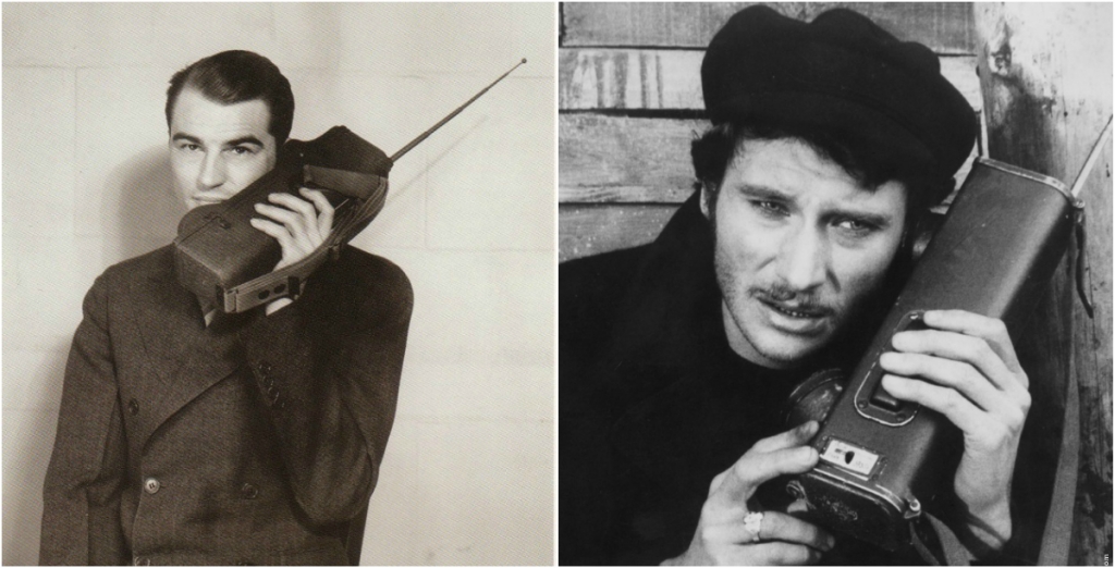
Мартин Купер — изобретатель прототипа портативного сотового телефона Motorola DynaTAC весом в 1,15 кг и размерами 22,5х12,5х3,75 см

Если в западных странах к середине 90-х годов прошлого века сотовая связь была распространена повсеместно и ей пользовалась большая часть населения, то в России она только начала появляться, и стала доступной для всех чуть более 10 лет назад.
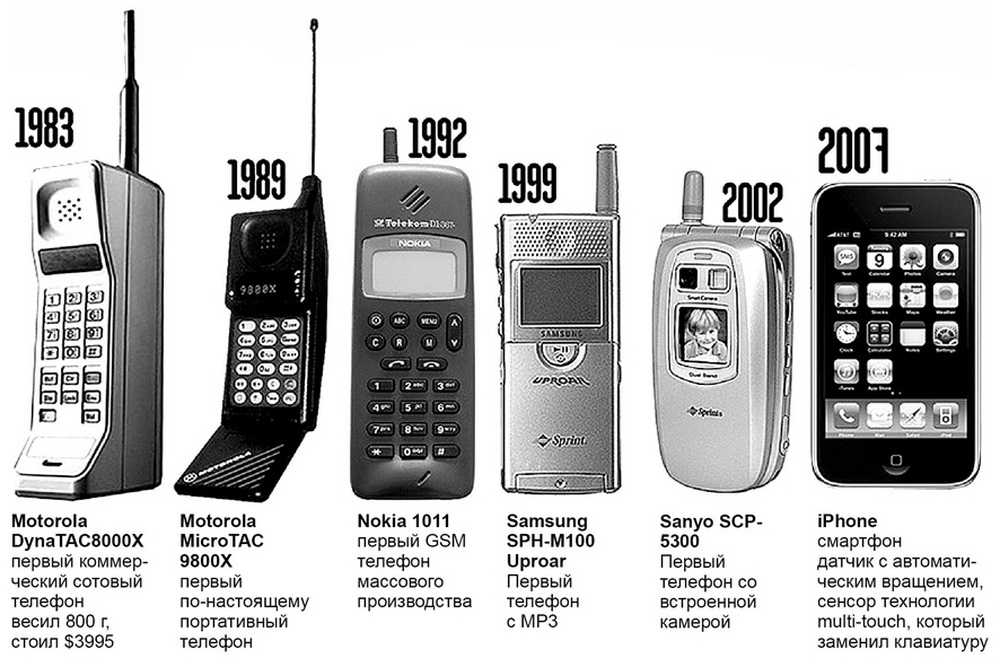
Громоздкие кирпичеобразные мобильники работавшие в форматах первого и второго поколений ушли в историю, уступив место смартфонам с 3G и 4G, лучшей голосовой связью и высокой скоростью интернета.
Почему связь называется сотовой? Потому что территория, на которой обеспечивается связь, разбивается на отдельные ячейки или соты, в центре которых располагаются базовые станции (БС). В каждой «соте» абонент получает одинаковый набор услуг в определенных территориальных границах. Это означает, что перемещаясь от одной «соты» к другой, абонент не чувствует территориальной привязанности и может свободно пользоваться услугами связи.
Очень важно, чтобы была непрерывность соединения при перемещении. Это обеспечивается благодаря так называемому хэндовер (Handover), при котором соединение установленное абонентом как бы подхватывается соседними сотами по эстафете, а абонент продолжает разговаривать или копаться в соцсетях.
Вся сеть делится на две подсистемы: подсистема базовых станций и подсистема коммутации. Схематически это выглядит так:

В середине «соты», как было сказано выше находится базовая станция, которая обычно обслуживает три «соты». Радиосигнал от базовой станции излучается через 3 секторные антенны, каждая из которых направлена на свою «соту». Бывает так, что на одну «соту» направлены сразу несколько антенн одной базовой станции. Это связано с тем, что сеть сотовой связи работает в нескольких диапазонах (900 и 1800 МГц). Кроме того, на данной базовой станции может присутствовать оборудование сразу нескольких поколений связи (2G и 3G).
Но на вышках БС Tele2 стоит оборудование только третьего и четвертого поколения — 3G/4G, так как компания решила отказаться от старых форматов в пользу новых, которые помогают избегать обрывов голосовой связи и обеспечивают более стабильный интернет. Завсегдатаи соцсетей поддержат меня в том, что в наше время скорость интернета очень важна, 100-200 кб/с уже не достаточно, как это было пару-тройку лет назад.
Наболее привычным местом размещения БС является башня или мачта, построенная специально для нее. Наверняка вы могли видеть красно-белые вышки БС где-то в отдаленности от жилых домов (в поле, на холме), или там, где поблизости нет высоких зданий. Как вот эта, которая видна из моего окна.

Однако, в условиях городской местности трудно найти место под размещение массивного сооружения. Поэтому в крупных городах базовые станции размещаются на зданиях. Каждая станция ловит сигнал от мобильных телефонов на удалении до 35 км.

Это антенны, само оборудование БС находится на чердаке, или в контейнере на крыше, которое представляет из себя пару железных шкафов.

Некоторые базовые станции расположены там, где вы даже не догадаетесь. Как например на крыше этой парковки.


Антенна БС состоит из нескольких секторов, каждый из которых принимает/отправляет сигнал в свою сторону. Если вертикальная антенна осуществляет связь с телефонами, то круглая соединяет БС с контроллером.

В зависимости от характеристик, каждый сектор может обслуживать до 72 звонков одновременно. БС может состоять из 6 секторов, и обслуживать до 432 звонков, однако обычно на станциях устанавливают меньше передатчиков и секторов. Сотовые операторы, такие как Tele2, предпочитают ставить больше БС для улучшения качества связи. Как мне сказали, здесь используется самое современное оборудование: базовые станции Ericsson, транспортная сеть — Alcatel Lucent.

От подсистемы базовых станций сигнал передается в сторону подсистемы коммутации, где и происходит установление соединения с нужным абоненту направлением. В подсистеме коммутации есть ряд баз данных, в которых хранятся сведения об абонентах. Кроме того эта подсистема отвечает за безопасность. Если сказать проще, то коммутатор выполняет те же функции, что и девушки операторы, которые раньше руками соединяли вас с абонентом, только сейчас все это происходит автоматически.
Оборудование для этой базовой станции спрятано в этом железном шкафу.

Кроме обычных вышек есть также и мобильные варианты базовых станций, размещенные на грузовиках. Их очень удобно использовать во время стихийных бедствий или в местах массового скопления людей (футбольные стадионы, центральные площади) на время праздников, концертов и различных мероприятий. Но, к сожалению, из-за проблем в законодательстве широкого применения они пока не нашли.

Для обеспечения оптимального покрытия радиосигналом на уровне земли, базовые станции проектируются специальным образом, потому несмотря на дальность в 35 км. сигнал не распространяется на высоту полета самолетов. Однако некоторые авиакомпании уже начали устанавливать на своих бортах небольшие базовые станции, обеспечивающие сотовую связь внутри самолета. Такая БС соединяется с наземной сотовой сетью с помощью спутникового канала. Система дополняется панелью управления, которая позволяет экипажу включать и выключать систему, а также отдельные типы услуг, например, выключать голос на ночных рейсах.
Также я заглянул в офис Tele2, чтобы увидеть как специалисты контролируют качество сотовой связи. Если несколько лет назад такая комната была бы увешана до потолка мониторами показывающими данные сети (загруженность, аварии сети, и т.п.) то со временем надобность в таком количестве мониторов отпала.

Технологии со временем сильно развились и достаточно вот такой небольшой комнаты с несколькими специалистами, чтобы наблюдать за работой всей сети в Москве.

Немного видов из офиса Tele2.


На совещании сотрудников компании обсуждаются планы по захвату столицы) С начала стройки до сегодняшнего дня Tele2 успел покрыть своей сетью всю Москву, и постепенно завоевывает Подмосковье, запуская более 100 базовых станций еженедельно. Так как я живу теперь в области, мне очень важно. чтобы эта сеть как можно быстрее пришла в мой городок.
В планах компании на 2016 г. обеспечение высокоскоростной связи в метро на всех станциях, на начало 2016 связь Tele2 присутствует на 11 станциях: связь стандарта 3G/4G на метро «Борисово», «Деловой центр», «Котельники», «Лермонтовский проспект», «Тропарево», «Шипиловская», «Зябликово», 3G: «Белорусская» (Кольцевая), «Спартак», «Пятницкое шоссе», «Жулебино».

Как я говорил выше, Tele2 отказалась от формата GSM в пользу стандартов третьего и четвертого поколения — 3G/4G. Это позволяет устанавливать базовые станции 3G/4G с большей частотой (например, внутри МКАД БС стоят на расстоянии около 500 метров друг от друга), чтобы обеспечивать более стабильную связь и высокую скорость мобильного интернета, чего не было в сетях предыдущих форматов.
Из офиса компании я в компании инженеров Никифора и Владимира отправляюсь на одну из точек, где им нужно замерить скорость связи. Никифор стоит напротив одной из мачт, на которой установлено оборудование для обеспечения связи. Если приглядитесь, то заметите чуть далее слева еще одну такую мачту, с оборудованием других сотовых операторов.
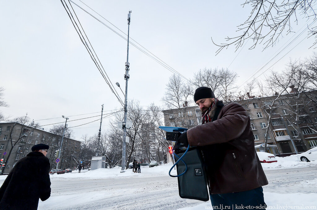
Как это ни странно, но сотовые операторы часто разрешают своим конкурентам использовать свои башенные сооружения для размещения антенн (естественно на взаимовыгодных условиях). Это вызвано тем, что строительство башни или мачты — дорогое удовольствие, и такой обмен позволяет сэкономить немало средств!

Пока мы замеряли скорость связи, Никифора несколько раз прохожие бабушки и дядьки спросили не шпион ли он)) «Да, глушим радио «Свобода»!).

Оборудование на самом деле выглядит необычно, по его виду можно предположить все что угодно.

У специалистов компании немало работы, если учесть, что в Москве и области у компании более 7тыс. базовых станций: из них порядка 5тыс. 3G и около 2тыс. базовых станций LTE, а за последнее время количество БС увеличилось еще примерно на тысячу.
Всего за три месяца в Подмосковье было выведено в эфир 55% от общего количества новых базовых станций оператора в регионе. В настоящий момент компания обеспечивает качественное покрытие территории, на которой проживает более 90% населения Москвы и Московской области.
Кстати, в декабре сеть 3G Tele2 была признана лучшей по качеству среди всех столичных операторов.

Но я решил лично проверить насколько хороша связь у Tele2, потому приобрел симку в ближайшем ко мне торговом центре на м.Войковская, с самым простым тарифом «Очень черный» за 299 р (400 смс/минут и 4 ГБ). Кстати, у меня был подобный билайновский тариф, который на 100 рублей дороже.

Проверил скорость не отходя далеко от кассы. Прием — 6.13 Mbps, передача — 2.57 Mbps. Учитывая, что я стою в центре торгового центра это неплохой результат, связь Tele2 хорошо проникает сквозь стены большого ТЦ.

На м.Третьяковская. Прием сигнала — 5.82 Mbps, передача — 3.22 Mbps.

И на м.Красногвардейская. Прием — 6.22 Mbps, передача — 3.77 Mbps. Замерил у выхода из метро. Если принять во внимание, что это окраина Москвы, очень даже прилично. Считаю, что вполне приемлемая связь, уверенно можно сказать, что стабильная, если учитывать, что Tele2 появилась в Москве всего пару месяцев назад.

В столице стабильная связь Tele2 есть, это хорошо. Очень надеюсь, что они побыстрее придут в область и я смогу в полной мере пользоваться их связью.
Теперь и вы знаете как работает сотовая связь!
Если у вас есть производство или сервис, о котором вы хотите рассказать нашим читателям, пишите пишите мне — Аслан (shauey@yandex.ru) и мы сделаем самый лучший репортаж, который увидят не только читатели сообщества, но и сайта http://ikaketosdelano.ru
Подписывайтесь также на наши группы в фейсбуке, вконтакте, одноклассниках и в гугл+плюс, где будут выкладываться самое интересное из сообщества, плюс материалы, которых нет здесь и видео о том, как устроены вещи в нашем мире.
Жми на иконку и подписывайся!


