Современные пользователи редко испытывают проблемы при поиске ЗУ для своих смартфонов. Разъём сейчас почти на всех гаджетах одинаков, что очень удобно. Однако это не значит, что так было и будет всегда. Прочитайте статью о прошлом и будущем технологии USB.
Пользователям мобильных устройств в 2000-х пришлось нелегко – они были вынуждены мириться с так называемой проприетарностью. Телефоны каждого из производителей оснащались уникальными разъёмами для зарядки – как следствие, ЗУ, например, для Nokia не работало с телефоном Motorola. Доходило и до абсурда – когда для двух телефонов одного производителя (финского) приходилось искать различные зарядные устройства. Недовольство пользователей оказалось настолько сильным, что вмешаться был вынужден Европарламент.
Сейчас ситуация в корне иная: практически все производители смартфонов оснащают свои гаджеты портами под зарядные устройства одного типа. Пользователю больше не приходится покупать новое ЗУ «в довесок» к телефону.
Содержание
- 1 Какие бывают разъёмы USB для смартфонов?
- 2 Какими бывают USB-кабели для смартфонов?
- 3 Что такое стандарт OTG?
- 4 USB Type-C: в чём преимущества?
- 5 Заключение
Кабели USB можно применять не только для передачи данных с ПК на гаджет, но и для зарядки мобильного устройства. Смартфоны способны пополнять «запасы» аккумулятора как от розетки, так и от компьютера, однако во втором случае зарядка займёт существенно больше времени. Традиционный кабель USB для смартфона с Android или с Windows Phone выглядит следующим образом:

Подобные кабели USB можно найти в различных расцветках на страницах каталога магазина GearBest.
На одном из его концов присутствует стандартный штекер USB 2.0 Type-A:

Этот штекер вставляется в USB-порт на компьютере или ноутбуке.
На втором конце провода – штекер microUSB.
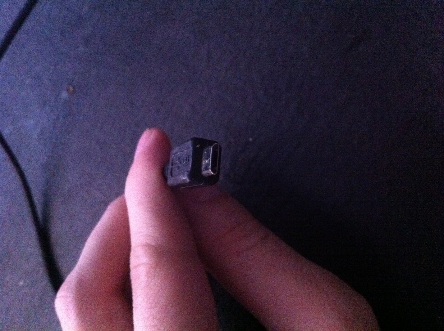
Он, соответственно, вставляется в разъём микро-USB на мобильном устройстве.
Именно micro-USB 2.0 является сейчас унифицированным разъёмом: встретить его можно на смартфонах и планшетах почти всех производителей мобильной техники (за исключением Apple). Соглашение о стандартизации интерфейсов было подписано в 2011 году представителями 13-и компаний, лидирующих на мобильном рынке.
На Micro-USB выбор пал по ряду причин:
- Разъём компактен. Его физические размеры составляют всего лишь 2×7 миллиметров – это примерно в 4 раза меньше, чем у USB 2.0 Type-A.
- Штекер прочен – особенно если сравнивать с тонкой зарядкой Nokia.
- Разъём способен обеспечивать высокую скорость передачи данных. Теоретически скорость передачи через Micro-USB при использовании стандарта 2.0 может достигать 480 Мбит/сек. Фактическая скорость гораздо ниже (10-12 Мбит/сек в режиме Full Speed), однако пользователям это редко доставляет неудобства.
- Разъём поддерживает функцию OTG. Подробнее о том, какие преимущества это даёт, расскажем позже.
Конкуренцию micro-USB в борьбе за роль стандартного разъёма мог навязать Mini-USB. Мини-штекер выглядит так:

Этот вид USB-разъёма не подошёл в качестве стандартного, и вот почему:
- Разъём больше по размерам – пусть и ненамного. Величина его – 3×7 миллиметров.
- Разъём достаточно хрупкий – из-за отсутствия жёстких креплений он очень быстро расшатывается. Вследствие этого передача данных через кабель становится для пользователя настоящим мучением.
В 2000-х разъём вида mini-USB можно было встретить на смартфонах производителей «второго сорта» — скажем, Philips и Alcatel. Сейчас мобильных гаджетов с мини-разъёмом на рынке не найдёшь.
Помимо тех USB-разъёмов, о которых мы упомянули (Micro-USB, Mini-USB, USB Type-A), есть и другие. Например, micro-USB стандарта 3.0 может использоваться для подключения к ПК жёстких дисков, а USB Type-B (квадратной формы) – для музыкальных инструментов (в частности, MIDI-клавиатуры). К мобильной технике эти разъёмы не имеют прямого отношения (если не считать Galaxy Note 3 c USB 3.0), поэтому более подробно мы о них рассказывать не будем.
Какими бывают USB-кабели для смартфонов?
Благодаря неистощимой фантазии китайских рукодельцев пользователи мобильной техники могут купить кабели совершенно разных формаций. Например, в эпоху проприетарности невероятной популярностью пользовался такой вот «монстр»:
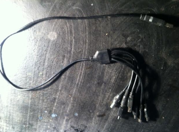
Да, эта зарядка подходила ко всем основным разъёмам!
Подобные «мультитулы» и сейчас есть в продаже, однако штекеров у них поубавилось. Вот зарядка 4-в-1, которую можно заказать на GearBest дешевле, чем за 200 рублей:
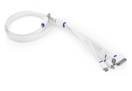
Эта зарядка оснащена всеми современными штекерами – Lightning, 30Pin (оба для iPhone), microUSB, USB 3.0. Однозначно, «must-have» для пользователя!
Есть и другие любопытные варианты. Вот кабель от OATSBASF для тех, кто терпеть не может кабели:

Такой называется кабелем с функцией Stretch. Визуально он чем-то похож на игрушку Йо-Йо. Провод вытягивается на ту длину, которая необходима, а по окончании использования сматывается. Это очень удобно, потому как владельцу гаджета не приходится постоянно распутывать клубки проводов. Минус стретч-кабеля заключается в цене: по сравнению с обычными USB-кабелями на GearBest он почти вдвое дороже.
Вот ещё одно любопытное решение, предлагаемое GearBest – карманный кабель-брелок:

Этот кабель позволяет подзаряжать от компьютера два мобильных устройства одновременно (например, 5-ый Айфон и Android) и имеет очень соблазнительную цену – чуть более 100 рублей.
В отечественных магазинах и салонах пользователь, конечно же, не найдёт такого изобилия разнообразных кабелей, как на страницах каталогов GearBest и AliExpress. Кроме того, Data-оборудование в рознице стоит существенно дороже. По этим двум причинам пользователям рекомендуется заказывать USB-кабели именно из Китая.
Что такое стандарт OTG?
Наверняка многие видели такой кабель и задумывались, для чего он нужен:

Это кабель OTG; на одном его конце — штекер micro-USB, на втором – разъём USB 2.0, «мама». С помощью такого кабеля к смартфону или планшету можно подключить USB-флэшку, но только в том случае, если само мобильное устройство поддерживает стандарт OTG.
OTG (сокращение от On-The-Go) – это функция, предназначенная для быстрого соединения 2-х USB-устройств друг с другом, без посредничества компьютера. Подключить по OTG можно не только флэшку (хотя это, конечно, самый распространённый случай), но также, например, и компьютерную мышку, клавиатуру, внешний жёсткий диск, игровой руль, джойстик. Получится даже подсоединить смартфон к принтеру или МФУ, чтобы распечатать снимок, сделанный на камеру гаджета.
Кабели OTG для iPhone уже тоже появились, однако загрузить на «яблочное» устройство (без джейлбрейка) с внешнего носителя получается только фото и видео – и то лишь тогда, когда корневые папки на флэшке и сами фотографии имеют «правильные» названия.
Полного перечня смартфонов, поддерживающих функцию OTG, нет – просто потому, что наличием этого стандарта способны похвастать почти все современные гаджеты и список был бы огромен. Тем не менее, покупателю, намеревающемуся подключать к девайсу мышь или флэшку, стоит осведомиться у консультанта салона-магазина о поддержке OTG до того, как отдавать деньги – «на всякий пожарный».
USB Type-C: в чём преимущества?
Переход с micro-USB на USB Type-C – это новый тренд рынка мобильной электроники! Производители активно осваивают технологию и оснащают свои флагманские модели усовершенствованными разъёмами для зарядки и передачи данных. USB Type-C долго ждал «в тени»: разъём был создан ещё в 2013 году, однако только в 2016-м лидеры рынка обратили на него внимание.
Выглядит USB Type-C так:

В чём же заключаются преимущества Type-C перед привычным всем micro-USB?
- Высокая скорость передачи данных. Пропускная способность Type-C равняется 10 Гб/сек (!). Но это только пропускная способность: в действительности на такую скорость смогут рассчитывать лишь владельцы смартфонов со стандартом USB 3.1 – например, Nexus 6P и 5X. Если гаджет использует стандарт USB 3.0, скорость окажется на отметке примерно в 5 Гб/сек; при USB 2.0 передача данных будет происходить существенно медленнее.
- Быстрая зарядка. Продолжительность процедуры зарядки смартфона зависит от потенциального количества Вт, которые поставляются разъёмом. USB стандарта 2.0 способно подавать всего 2.5 Вт – оттого зарядка и длится часы. Разъём USB Type-C обеспечивает 100 Вт – то есть в 40 раз (!) больше. Любопытно то, что передача тока может происходить в обе стороны – как к хосту, так и от него.
- Симметричность коннектора. Если у коннектора micro-USB есть верх и низ, то коннектор Type-C симметричен. Какой стороной его вставлять в разъём, значения не имеет. С этой точки зрения технология USB Type-C похожа на Lightning от Apple.
Достоинством Type-C является также небольшая величина разъёма – всего лишь 8.4×2.6 миллиметра. По этому критерию технологии micro-USB и USB Type-C схожи.
У USB Type-C есть и недостатки, один из которых более чем существенный. Из-за нерегулируемой работы коннектора зарядка запросто может «поджарить» мобильное устройство. Такая вероятность не является чисто теоретической – возгорания случались и на практике. Именно по этой причине распространение неоригинальных, «кустарных» кабелей и зарядок USB Type-C запрещено.
Разъём USB Type-C уже установлен на следующих мобильных устройствах: Microsoft Lumia 950XL, LG G5 SE, HTC 10 Lifestyle, Huawei Honor 8, Asus Zenfone 3.
Заключение
Несмотря на возрастающую популярность USB Type-C, стандартный разъём USB в ближайшее время точно не «канет в Лету». Это не просто субъективное предположение, об этом говорит Дж. Рэйвенкрафт, президент компании USB Implementers Forum, поддерживающей и развивающей технологию USB. Рэйвенкрафт называет совершенно сумасшедшую цифру – 20 миллиардов; по его данным именно столько устройств в мире сейчас оснащено стандартными разъёмами USB-A.
Из-за подобной массовости новую технологию будут вводить эволюционно, а не революционно – чтобы пользователи имели возможность самостоятельно убедиться в преимуществах Type-C и принять решение об отказе от стандартного разъёма. При этом Рэйвенкрафт допускает, что, возможно, полного замещения USB-A не произойдёт никогда.
Главная » Уроки и статьи » Железо
Виды разъемов для зарядки телефонов
Когда-то у разъемов для зарядки мобильников было только одно предназначение – собственно, заряжать аппарат. При этом почти у каждого крупного производителя имелся свой стандарт, и зарядное устройство или кабель от одного телефона не подходили к другому. Но уже в начале двухтысячных компании обратили внимание на недовольство потребителей и стали чаще использовать в своих девайсах не проприетарные, а унифицированные решения.
MicroUSB
Самым известным и популярным из таких решений стал разъем MicroUSB, позволяющий не только производить зарядку девайса, но и передавать данные. С его распространением отпала необходимость иметь свое зарядное устройство для каждого гаджета, а кабель MicroUSB/USB Type-A стал универсальным способом подключить смартфон как к заряднику, так и к компьютеру или ноутбуку.

Важно: от ПК телефон заряжается гораздо медленнее, чем от зарядного устройства, подключенного напрямую к розетке. Если вы хотите зарядить девайс максимально быстро – переведите его в режим полета и используйте зарядник.
Габариты разъема – всего 7×2 мм. Именно компактность стала одним из главных факторов, сыгравших в его пользу, когда производители выбирали между MicroUSB и MiniUSB вариантами. Стандарт обеспечивает мощность до 2.5 Вт и позволяет полностью зарядить телефон за 1-5 часов, в зависимости от емкости аккумулятора, а также характеристик ЗУ и самого аппарата. Максимальная скорость передачи данных через такой разъем в теории может составлять до 480 Мбит/с, но на практике ограничивается многими факторами и может быть в несколько раз ниже.
В 2009 году 13 фирм, выпускающих смартфоны и другую цифровую технику, включая такие крупные, как Samsung и Apple, подписали документ, подтверждающий их намерения стандартизировать разъемы и интерфейсы. Причины не только маркетинговые, но и политические, а также репутационные – европейские власти неоднократно призывали производителей не увеличивать количество разных зарядных устройств, которые потом требуется перерабатывать или утилизировать.
Спустя примерно год Европарламент опубликовал заявление с официальным призывом к производителям мобильных устройств перейти на единый стандарт. Подобная политика представителей различных государств сыграла свою роль в закреплении microUSB в качестве универсального разъема для зарядки гаджетов и передачи файлов. Отказались от него всего несколько компаний. Наиболее известная среди них – Apple.
Стандарт OTG
Ко многим моделям смартфонов и планшетов можно подключать те же модели флэшек, что и к ПК – требуется только поддержка устройством стандарта OTG и специальный переходник.

При помощи него можно подсоединить к телефону не только компактный флэш-накопитель, но и компьютерную мышку, клавиатуру или геймпад. Подойдет адаптер и для подключения принтера – документы и снимки можно печатать прямо с мобильного гаджета.
Lightning
Раньше в мобильных гаджетах компании из Купертино применялся фирменный стандарт Apple 30pin, но с 2012 года его сменил восьмиконтактный разъем Apple Lightning, по скорости зарядки и передачи данных схожий с MicroUSB. Призывы чиновников и медиа не привели к отказу от собственного разъема, вместо этого фирма выпустила ряд переходников, с помощью которых можно заряжать iPhone, используя обычные USB-зарядники.

USB Type-C
Стандарт, призванный заменить устаревающий microUSB — USB Type-C. Максимальная теоретическая скорость передачи данных через этот разъем – до 10 Гбит/с, что обеспечивается контактной группой с 24 выводами. Впрочем, все зависит от реализации в конкретной модели устройства – если производитель не предусмотрел поддержку USB 3.0 или 3.1, ограничившись USB 2.0, то прироста в скорости по сравнению с MicroUSB не будет. Кстати, габариты разъема — 8,34×2,56 мм. Чуть больше, чем у MicroUSB, но это незначительная плата за кратный выигрыш в производительности: USB Type-C остается очень компактным и может использоваться практически в любых устройствах.

Дополнительное преимущество обновленного интерфейса – симметричность овального коннектора. Теперь пользователям не придется несколько раз переворачивать штекер, ругаясь на инженеров, не знакомых с понятием «юзабилити». Скорость зарядки тоже заметно выросла, а максимальная теоретическая мощность, которую поддерживает интерфейс (с USB 3.1) доходит до 100 Вт, но такой вариант требует продвинутой реализации — стандартные профили ограничиваются 7.5-15 ваттами. Заявленный же механический ресурс не отличается от MicroUSB и составляет около 10000 подключений.
USB Type-C и USB 3.1 – в чем разница
Следует отличать форм-фактор коннектора от стандарта обмена данными. Например, формат USB Type-C может соответствовать разным спецификациям — USB 2.0, 3.0 или 3.1. В первом случае он способен передавать данные со скоростью до 480 Мбит/с, а в последнем – до 10 Гбит/с. MicroUSB разъемы на смартфонах соответствуют стандарту USB 2.0.
Фактическая скорость передачи информации обычно в разы меньше максимальной и может ограничиваться не только поддерживаемым стандартом, но и кабелем, портом смартфона, планшета или компьютера, производительностью контроллера и памяти, поэтому теоретический предел недостижим в реальных сценариях использования.
Исходя из вышесказанного, наличие у девайса разъема USB Type-C не является гарантией высокой скорости зарядки и передачи данных. Актуальную версию интерфейса стоит уточнять в технических спецификациях конкретных устройств, а затем сверять с пользовательским опытом — в этом помогут тематические форумы и другие профильные ресурсы.
Заключение
Почти все современные смартфоны и планшеты оснащены microUSB разъемом (все они соответствуют спецификациям USB 2.0) или USB Type-C с поддержкой USB 2.0, 3.0 или 3.1. Некоторые из них обладают функцией быстрой зарядки, требующей совместимого зарядного устройства – варианты реализации в моделях разных производителей в этом случае отличаются. MicroUSB медленно переходит в разряд разъема для недорогих устройств, а USB Type-C теперь встречается не только во флагманских смартфонах, но и в гаджетах средней ценовой категории, а иногда и в бюджетниках. При этом покупателям не стоит терять бдительность – перед покупкой нового девайса стоит ознакомиться с его характеристиками и уточнить, какую именно версию USB поддерживает конкретная модель, если она снабжена USB Type-C разъемом.
Исключением, не использующим microUSB или USB Type-C, являются iPhone – смартфоны от компании Apple имеют вместо него фирменный разъем Lightning, и для их зарядки при помощи USB-интерфейса нужен кабель-адаптер.
Понравилось? Поделись с друзьями!
Дата: 03.03.2019
Автор/Переводчик: Zio
На чтение 12 мин Просмотров 18.6к. Опубликовано 03.08.2021 Обновлено 10.02.2022
Содержание
- Выбор зарядного устройство для смартфона
- Типы зарядных устройств
- Виды разъемов для зарядки
- Lightning
- MicroUSB
- USB Type C
- Параметры тока
- Наличие быстрой зарядки
- Выбор USB провода
- Форма кабеля
- Материал оплетки
- Сила пропускного тока
- Плюсы и минусы магнитных штекеров
- Качество китайских зарядок и проводов
Каждый мобильный прибор комплектуется зарядным устройством. Но оно может выйти из строя или потеряться. Также проблема приобретения ЗУ может встать при покупке устройства с рук или если нужен адаптер для других видов работы (в автомобиле и т.п.).
Выбор зарядного устройство для смартфона
Чтобы правильно выбрать зарядное устройство, надо знать технические характеристики, определяющие потребительские свойства ЗУ. Не менее важно понимать, на что и в какую сторону влияет несоответствие параметров адаптера заданным в технических условиях на мобильный гаджет.
Типы зарядных устройств
Деление зарядок на виды можно выполнить по разным категориям — по схемотехнике, по КПД и т.п. Но для потребителя важнее, где и как он может применить ЗУ, поэтому лучше категорировать адаптеры по исполнению.
- Сетевые зарядные устройства. Включаются в бытовую сеть 220 вольт. В 99+ процентах случаев выполняются по импульсной схеме.
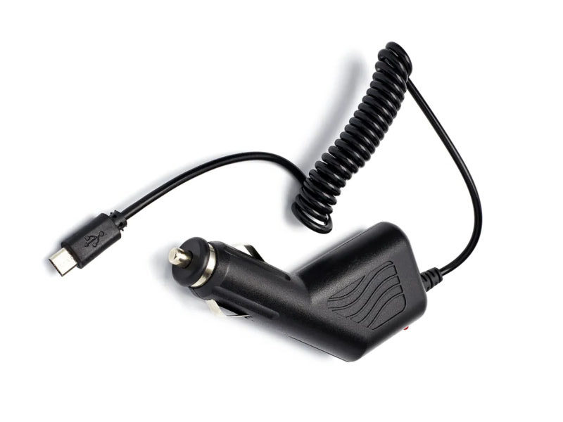
- Автомобильные зарядные устройства. Включаются в бортсеть автомобиля через разъем прикуривателя. Для упрощения схемотехники могут быть выполнены по линейной схеме.
- Зарядники от разъема USB. Представляют собой обычный шнур с разъемом USB A на одной стороне и соответствующим коннектором на другой.
В большинстве случаев мобильные гаджеты комплектуются штатным сетевым адаптером, а остальные виды надо покупать отдельно.
Виды разъемов для зарядки
В начале эпохи мобильных гаджетов производители устройств делали разъемы каждый под себя. Это приносило им определенную дополнительную прибыль, так как владелец был вынужден приобретать только оригинальные зарядные устройства – другие не соответствовали по форме штекера или напряжению, подобрать подходящий вариант было сложно. Неудобства приходилось терпеть пользователям. Сейчас ситуация изменилась, ведущие участники рынка мобильных гаджетов стремятся к стандартизации. В большинстве устройств используется три типа терминалов для зарядки и передачи данных.
Lightning
Этот разъем применяется в мобильных устройствах Apple. Он пришел на замену громоздкому 30-пиновому терминалу и является стандартом для гаджетов производства этой фирмы, хотя есть сведения о планах компании перейти на USB Type С. Разъем является двухсторонним – подключать можно как одной, так и другой стороной. Такое решение при разработке коннектора было применено впервые, и на тот момент это был прорыв.
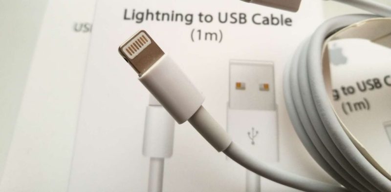
Преимуществами такого разъема является прочная конструкция, а также способность очищаться от загрязнений при подключении.

Если проанализировать расположение и назначение выводов в разъеме, становится очевидно, что функционал пинов несимметричен. Направление подключения определяется в момент соединения встроенной микросхемой. Эта же микросхема служит защитой от подделок.
| Номер | Маркировка | Функциональное назначение |
|---|---|---|
| 1 | GND | Земля (0V) |
| 2 | L0p | Линия (полоса) 0 + |
| 3 | L0n | Линия (полоса) 0 — |
| 4 | ID0 | Идентификация 0 |
| 5 | PWR | Напряжение питания |
| 6 | L1n | Линия (полоса) 1 — |
| 7 | L1p | Линия (полоса) 1 + |
| 8 | ID1 | Идентификация 0 |
MicroUSB
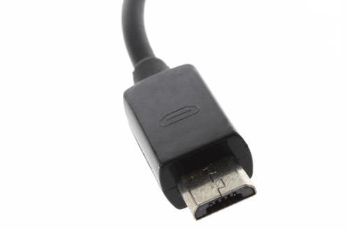
Этот разъем пришел на смену коннектору MiniUSB. Его видимое отличие от предыдущей модификации – размеры. На самом деле у microUSB появились и другие плюсы:
- увеличенная прочность и более длительный ресурс;
- повышенная надежность соединения.
К минусам относится необходимость позиционирования при подключении (разъем не является двусторонним подобно Type С или Lightning). Это привело к сокращению сектора использования данного терминала.

На шнурах для зарядки применяется вилка типа В, так как телефон в большинстве случаев выступает в роли периферийного устройства.
| № | Обозначение | Функция | Цвет изоляции провода |
|---|---|---|---|
| 1 | Vbus | Напряжение питания (+5 вольт) | Красный |
| 2 | D- | DATA- | Белый |
| 3 | D+ | DATA+ | Зеленый |
| 4 | ID | ON-the-GO ID | |
| 5 | GND | Общий провод (0V) | Черный |
Провод 4 определяет назначение разъема в режиме On-the-Go (когда дополнительные устройства подключаются к телефону напрямую) – соединение с общим проводом означает, что конец подключается к хосту, а если контакт ни с чем не соединен, коннектор подключается к периферийному устройству.
USB Type C
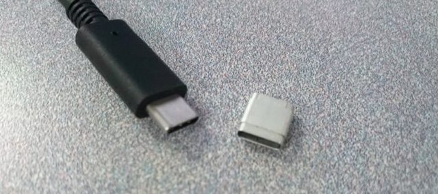
Самым распространенным и одновременно самым перспективным является разъем для мобильной техники USB Type C. Разработан для применения с гаджетами с операционной системой Андроид, но его используют и производители другой мобильной техники.

Овальная вилка содержит два ряда контактов – один ряд нумеруется от A1 до А12, другой – от B1 до B12. Контакты расположены симметрично, поэтому штекер можно вставлять любой стороной и никаких микросхем для определения положения не требуется. Контакты можно сгруппировать по функционалу.
| Номер пина | Маркировка | Назначение |
|---|---|---|
| 1,12 (A1, A12, B1, B12) | GND | 0 вольт |
| 4,9 | Vbus | + напряжения питания |
| 2,3,10,11 | TX+, TX-, RX+,RX- | Шина USB3.0 |
| 6,7 | D+, D- | Шина USB 2.0 |
| 5 | CC | Пин конфигурации |
| 8 | SBU | Дополнительный канал |
Шина питания распараллелена на два пина. Это позволяет передавать дополнительную мощность, которая у некоторых кабелей может достигать 100 ватт. Это подразумевает ток до 20 ампер при напряжении питания 5 вольт. Обычный шнур рассчитан на ток 1,5 или 3 ампера.
Выводы приемника (RX) и передатчика (TX) шины USB 3.0 в кабеле перекрещены (перекроссированы), поэтому то, что с одной стороны является входом приемника, на другой стороне подключается к выходу передатчика и наоборот. Пин конфигурации определяет:
- наличие подключенного периферийного устройства;
- потребные параметры питания периферии (ток и напряжение);
- некоторые другие функции в определенных ситуациях.
Пин SBU используется очень редко.
Разъем USB Type С обладает намного большими возможностями относительно Lightning и лучшими перспективами развития. Поэтому сведения о возможном переходе техники Apple на этот тип коннектора имеют под собой основания.
Для наглядности подкрепим видеоролик.
Параметры тока
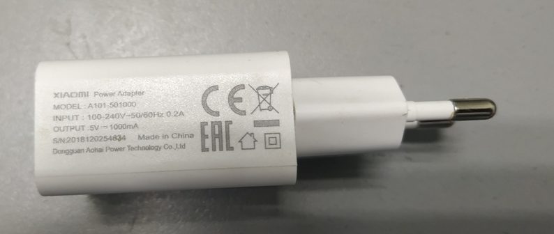
При выборе типа зарядных устройств в первую очередь надо обратить внимание на один из самых важных параметров – наибольший ток, который может выдавать адаптер. Чем меньше ток, тем дольше будет заряжаться аккумулятор, а если ЗУ рассчитано на совсем малый ток (0,5 А и меньше), то оно может отключаться по защите от перегрузки. Такая зарядка подойдет для заряжания беспроводных наушников и других маломощных устройств.
Для смартфонов среднего класса вполне подойдет ЗУ с током 1,0..1,5 А (1000..1500 мА). Для телефонов посерьезнее и другой техники с емкими АКБ надо выбирать адаптеры с током 1,5..3 А. Если устройство поддерживает функцию быстрой зарядки, то потребуется ток не менее 5 А. Самый простой способ определить потребный ток – посмотреть параметры на корпусе родного ЗУ и приобрести зарядку с не меньшей или большей мощностью.
Наличие быстрой зарядки
Некоторые смартфоны поддерживают быструю зарядку. Она производится большим током, поэтому надо выбирать ЗУ с соответствующими параметрами (от 5 А). Производители утверждают, что такой режим не повреждает аккумулятор, но это заявление достаточно лукавое. Явно вывести из строя аккумуляторную батарею повышенный в разумных пределах зарядный ток не может, но при этом значительно (в разы) сокращается ресурс батареи. Выбор за пользователем. Кроме того, не каждый гаджет поддерживает такой режим. Поэтому, прежде чем платить за дополнительную мощность, надо выяснить, понадобится ли подобная функция вообще.
Читайте также
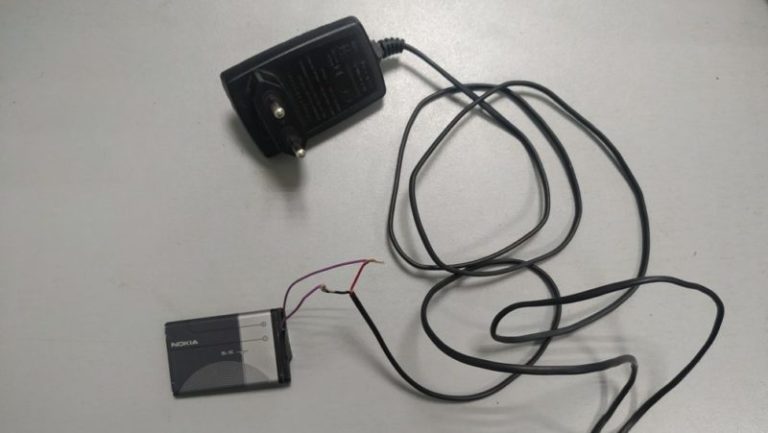
Заряжаем аккумулятор телефона без зарядного устройства
Выбор USB провода
Кроме сетевого адаптера, надо обратить внимание и на провод. Он выполняется съемным и продается отдельно.
Форма кабеля
Кабели чаще всего бывают плоские или круглые. На ток и время заряда форма влияния не оказывает, это просто удобство использования (большей частью, личные предпочтения):
- плоский шнур меньше склонен к запутыванию;
- круглый занимает меньше места в скрученном положении.
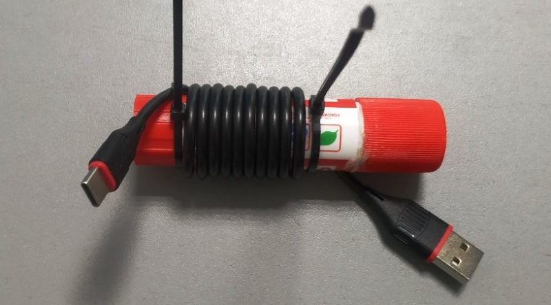
Большее значение имеет длина кабеля – чем он короче, тем он меньше ограничивает ток зарядки. В коротком шнуре меньше потерь, что важно при зарядке от PowerBank. Зато длинный в некоторых случаях предпочтительнее – когда надо работать и одновременно заряжать гаджет, а источник питания находится далеко. В отдельных ситуациях удобно применять шнур, завитый в форме пружины – он также не склонен к запутыванию.
Спиральный шнур можно сделать самостоятельно. Для этого его надо намотать на подходящую оправку (концы можно закрепить, например, пластиковыми хомутами) и прогреть кабель феном. После полного остывания получившийся спиральный шнур готов к применению. Если фена нет, намотанный на оправку провод можно ненадолго опустить в кипящую воду, следя, чтобы жидкость не попала в разъемы.
Материал оплетки
Большинство шнуров выпускаются в обычной ПВХ-изоляции. Она имеет отличные электрические свойства, но ее устойчивость к механическому воздействию, включая перетирание, невысока. Также у такого шнура высока вероятность перелома проводников при сгибании под малыми радиусами. Поэтому часто кабели для зарядки дополняют оплеткой, которая выполняется из различных материалов (по убыванию защитных свойств):
- металлическая – самая прочная, но наименее гибкая оплетка;
- плетеная оболочка из полимеров;
- гладкая оплетка из пластика (наиболее бюджетный вариант).
На электрические характеристики дополнительная оболочка влияния не оказывает, при ремонте кабеля ее часто просто удаляют.
Сила пропускного тока
От толщины проводника и материала зависит, будет ли он греться при достаточно большом токе зарядки. На самом деле, провода, сечением 0,75 кв. мм (диаметр без изоляции 1 мм) разумной длины хватит, чтобы без проблем работать при токах до 8 А. Этого хватит на все случаи жизни. Провода меньшего диаметра не используются по соображениям механической прочности. Да и определить даже на глаз сечение проводящей жилы непросто – она находится под изоляцией.
Но если есть подозрения, что толщина проводников все же невелика по отношению к заявленному току, лучше воздержаться от покупки такого шнура. Возможен перегрев и даже возгорание. Окончательно ток заряда определяется по меньшему из двух значений – наибольший ток адаптера или наибольший допустимый ток шнура.
Плюсы и минусы магнитных штекеров
Не так давно в продажу стали поступать магнитные разъемы для телефона, которые быстро обрели популярность. Суть такого коннектора в том, что в гнездо телефона вставляется дополнительный переходник, с одной стороны которого установлен штекер, соответствующий терминалу телефона, а с другой – две (или больше) магнитные контактные площадки.
На шнуре к зарядному устройству находится ответная часть, которая сопрягается с переходником посредством магнитного поля, создаваемого постоянными магнитами. На расстоянии порядка одного-двух сантиметров обе стороны притягиваются и становятся в рабочее положение. При этом не надо искать визуально или на ощупь точное местонахождение розетки на телефоне и не надо определять полярность подключения для разъема microUSB. Особенно это удобно при езде в автомобиле. При этом шнур лишний раз не перекручивается, что продлевает срок его службы.
Механические нагрузки на гнездо телефона сокращаются в несколько раз, что также продлевает период надежной работы. К плюсам также можно отнести защиту внутреннего разъема гаджета от попадания грязи.
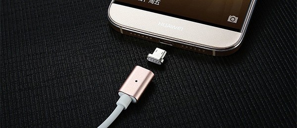
Но у такого коннектора есть и недостатки. В первую очередь, это появление лишнего разъемного контакта, а значит дополнительного источника ненадежности. Кроме того, этот контакт несколько снижает зарядный ток и увеличивает время пополнения энергии. Загрязнение открытой поверхности коннектора может привести к ухудшению качества контакта и к еще большему ограничению зарядного тока, а магнит способен притягивать металлическую пыль. Твердые частицы на поверхности также мешают надежному сопряжению.
Многие магнитные разъемы имеют всего две контактные площадки, предназначенные для зарядного напряжения. Это означает, что для передачи данных в шнуре просто нет проводников, и, например, скачать файлы с компьютера с помощью такого кабеля нельзя. Для тех шнуров, что такую возможность дают, нужен специальный переходник с большими размерами. Он заметно выступает за габариты гаджета. И немаловажный факт – стоит магнитный шнур дороже, чем обычный.
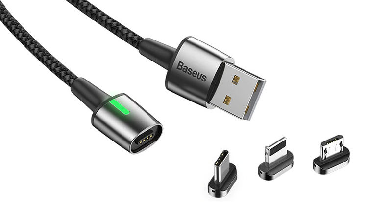
Видео-обзор магнитных кабелей.
Качество китайских зарядок и проводов
Дешевые зарядные устройства и кабели от неизвестных производителей из Юго-Восточной Азии могут быть некачественными. В первую очередь это относится к применению в проводниках вместо меди сплавов неизвестного состава. Это может привести к перегреву или ограничению зарядного тока. К этому же эффекту приводят заниженное сечение проводов и некачественная пайка (а то и обжимное соединение) разъемов. Упрощенная схемотехника может привести к неоптимальным режимам зарядки, что снижает ресурс АКБ. А самое простое, но неприятное – срок жизни таких устройств, как правило, недолог, и подвести такой адаптер может в любой момент.
Выбирать зарядное устройство для мобильного гаджета надо осознанно. В противном случае не избежать не только разочарований, но и технических проблем. А в худшем случае еще и финансовых потерь.

Первый разъём в телефонах предназначался именно для зарядки гаджета. У каждого производителя свои стандарты, поэтому раньше часто зарядное устройство от одного сотового не подходило по размерам к другому. В начале 2000 годов фирмы учли неудобства и непрактичность разъёмов и стали использовать унифицированные варианты.

Оглавление
- 1 Какие бывают разъёмы для зарядки телефонов
- 1.1 Micro USB
- 1.2 Lightning
- 1.3 Type-С
Какие бывают разъёмы для зарядки телефонов
Существует несколько разновидностей универсальных разъёмов, предназначенных для зарядки мобильного телефона.
Micro USB

Сегодня этот разъём применяется практически во всех телефонах Андроид, кроме Type-C. Провод не только заряжает гаджет, но и переносит данные на компьютер или ноутбук. Шнур постепенно уходит на второй план, но остаётся востребованным из-за следующих преимуществ:
- компактные размеры – 2 х 7 мм;
- прочный штекер;
- поддержка OTG;
- быстрая передача информации;
- удобно пользоваться;
- универсальность – он как заряжает гаджет, так и работает с данными – принимает их или передаёт.
Обеспечение телефона OTG позволяет им выступать в роли хостов. Если нужно перекинуть данные сразу из смартфона на комп, то опция позволит это сделать без посредников. Также к гаджету можно подсоединить любое устройство – накопитель, мышь, клавиатуру, наушники.
Микро USB бывают разных видов. Версия 2.0 типа применяется в гаджетах по умолчанию. Это стандарт для последних модификаций планшетов и телефонов. Второй разъём 3.0 ставят только на смартфонах и сотовых некоторых марок.
Lightning

Такой разъём использует компания Aplle, она же его и создала. Тип зарядки стоит дорого. Китайцы продают подделки за половину стоимости, но они могут быстро выходить из строя, поскольку даже оригинальные шнуры часто рвутся из-за своей хрупкости. Преимущества зарядки:
- благодаря 8 контактам устройство заряжается быстрее;
- данные передаются с высокой скоростью;
- некрупные габариты;
- отверстие в гаджете не расшатывается;
- возможно подсоединить любой стороной.
Type-С

Разновидность создали в 2014 году. Разъём у шнура овальной формы и симметричный, поэтому его вставляют любой стороной. Новая зарядка потребовалась для облегчения работы стандарта USB 2.0 – у него только 4 контакта, тогда как в версии 3.1 их 24. Благодаря высокой мощности разъём является универсальным и обладает следующими преимуществами:
- Быстро заряжает гаджет. Type-С передаёт заряд 100 Вт. Телефон с простым разъёмом micro USB заряжается около 4 часов, с Type-С он будет готов к работе буквально через час.
- У него удобный двусторонний шнур, который пользователь подключает любой стороной. Это удобно, когда плохая освещённость и не видно, как воткнуть провод.
- Быстро передаёт информацию. Стандарт 3.1 поддерживает скорость до 10 Гбит в секунду. Огромные объёмы данных с гаджета можно перемещать очень оперативно, а если к нему подсоединить монитор, то он станет показывать видеоклипы с высоким разрешением.
Телефонами можно было и раньше пользоваться как ПК, подсоединяя к ним разные приборы. С Type-С потенциал этой функции увеличен благодаря высокой мощности. Но не все разъёмы оснащены версией 3.1.
Некоторые фирмы оснащают смартфоны разъёмами Type-С, но внутри ставят USB 3.0. Он отличается более слабыми техническими характеристиками. Могут даже внедрить версию 2.0. Поэтому перед приобретением девайса следует убедиться, что стоит именно 3.1.

Зарядка Type-C установлена на следующих моделях:
- Huawei Honor 8;
- LG G5 SE;
- HTC 10 Lifestyle;
- Asus Zenfone 3;
- Microsoft Lumia 950XL.
В последние годы выросла популярность разъёма Type-C. Несмотря на это, привычный USB всё равно не уйдёт с рынка. По подсчётам около 20 миллиардов устройств в мире оснащены зарядкой USB типа А.
Разъемы USB есть в компьютерах, смартфонах и даже телевизорах. И все к ним привыкли. Но почему существует столько разновидностей? Чем они отличаются, кроме размера и формы? Читайте ниже.
Для начала, давайте определимся. Есть коннекторы (штекеры), а есть гнезда (разъемы, порты). Чтобы коннектор подошел к разъему, они должны быть одного стандарта.
Как выглядит разъем и штекер USB Type А
USB Type А – это стандартный плоский, прямоугольный коннектор, который можно найти хотя бы на одном конце каждого USB-кабеля. У большинства компьютеров есть от 4 до 6 портов USB-A для подключения различных устройств. Такие же гнезда можно найти на игровых приставках, телевизорах и других устройствах.
В свою очередь, штекер и разъем сконструированы таким образом, что надо подбирать какой стороной вставлять коннектор в гнездо.
Как выглядит разъем и штекер USB Type B
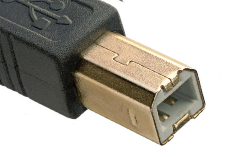
Не самые популярные коннектор и разъем. Почти квадратной формы со скошенными краями с одной стороны. Достаточно большие. Потому в смартфонах их не встретить. В основном, используются для подключения принтеров и других устройств, подключаемых к компьютеру.
Кстати, разъемы Mini и Micro, о которых мы поговорим ниже, считаются вариациями разъема типа B.
Чем отличается разъем и штекер Мини-USB (mini-USB)
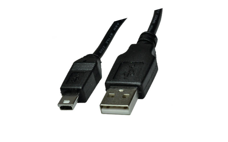
Меньший тип разъема B, который был самым популярным на мобильниках до появления micro-USB. Сегодня они встречаются не так часто. Только на некоторых камерах, контроллерах PlayStation 3, MP3-плеерах и т.д. А еще в GPS-навигаторах.
Самый маленький разъем это Micro-USB
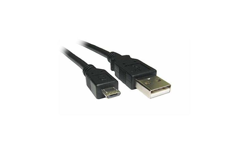
Пока еще самый популярный стандарт гнезда и штекера для мобильных и портативных устройств. Меньше, чем мини-USB. Собственно, потому и стал популярен на смартфонах. Не занимает много места. В последнее время стал уступать позиции USB-С. Из минусов Micro-USB можно отметить то, что приходится каждый раз подбирать какой стороной штекер включить в смартфон. В темноте так вообще очень неудобно.
В чем разница между Micro-USB A, Micro-USB B и Micro-USB AB
В свою очередь, разъем Micro-USB может быть двух вариантов: Micro-A и Micro-B. По аналогии с “полноценными” USB-A и USB-B, они отличаются формой. Тот что с буквой A – прямоугольный. А с буквой B – со скошенными краями.
Существуют также разъёмы типа Micro-AB, c которыми совместимы коннекторы и типа Micro A и Micro B.
Новенький разъем USB-С – одни плюсы
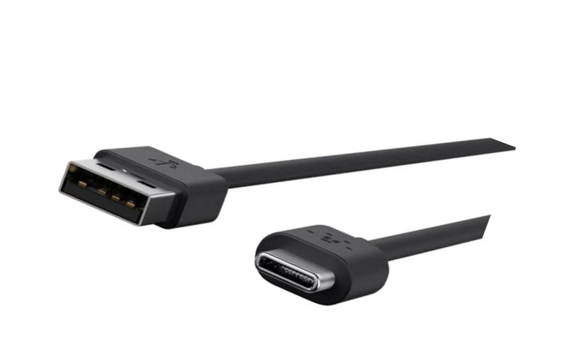
Новейший стандарт гнезда и коннектора USB. Вся его прелесть в том, что он двусторонний. А значит не надо подбирать, какой стороной его вставлять в телефон. Плюс поддерживает более высокую скорость передачи данных и большую мощность зарядки по сравнению с предыдущими типами USB. Не зря, стандарт быстрой зарядки USB-PD работает только на смартфонах, у которых есть USB-C. Такой разъем уже сейчас можно встретить на MacBook, в смартфонах Pixel и Nintendo Switch Pro.
Фирменный Lightning – только в айфонах и айпадах
Такой фирменный тип разъема вы можете встретить в технике Apple. По размеру он похож на USB-C и входит в стандартную комплектацию устройств Apple, выпускаемых с сентября 2012 года. Зачем Apple решила сделать свой фирменный разъем? Большой вопрос. Бытует мнение, чтобы побольше денежек содрать с владельцев айфонов и производителей аксессуаров.
Почему бывают разные разъемы USB с одним названием?
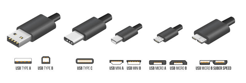
Все дело в стандартах (или поколениях USB). Вы, наверное, встречали надписи USB 1.0, USB 2.0 или USB 3. Они отличаются поддержкой некоторых функций, и, главное, скоростью передачи данных. Подробнее о них читайте здесь. А сейчас вы должны запомнить, что разъемы для поколения USB 3.0 могут иметь такие же названия, как для первого и второго поколения. Но при этом, у них совсем другая форма и контакты.
В приведенной ниже таблице показано, какие типы разъемов совместимы с какими стандартами. Обратите внимание, что устройства micro-USB, поддерживающие USB 3.x, имеют другой разъем.
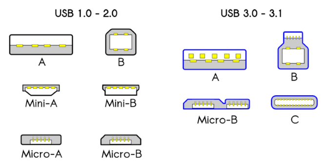
- Совместимость разъемов USB в зависимости от поколения USB
Все смартфоны и телефоны, у которых такие типы разъемов USB:
В выбранном устройстве разъём.
Как выглядят MicroUSB, USB Type-C и Apple Lightning кабели
Мы не будем углубляться в технические моменты, функциональные отличия этих интерфейсов, в данном аспекте это «ненужная» информация, мы просто покажем вам, как выглядят MicroUSB, USB Type-C и Apple Lightning кабели. Это позволит вам, просто взглянув на ваш кабель зарядки, с легкостью определить его интерфейс и сделать правильный выбор.
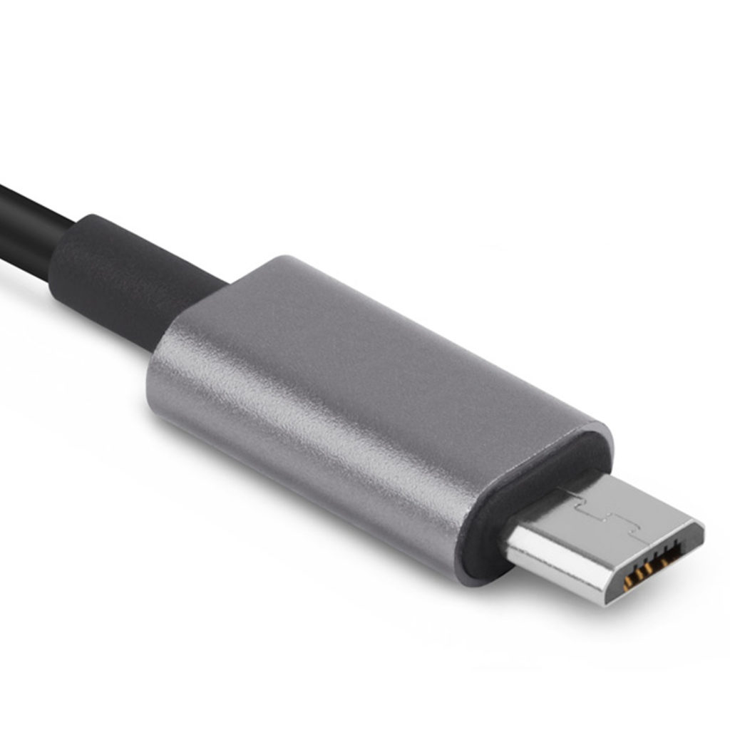
MicroUSB
Имеет трапециевидную форму и маленькие «усики» на нижней стороне коннектора
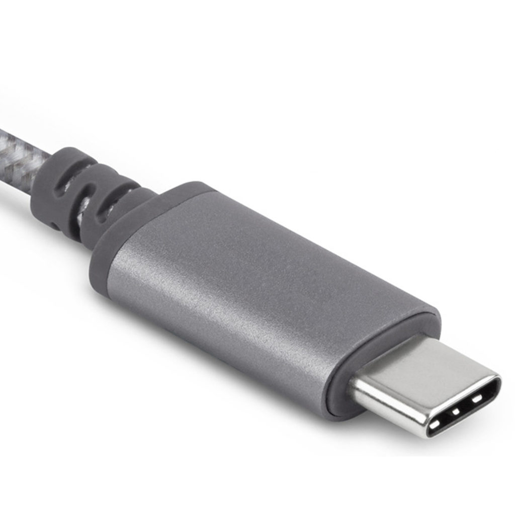
USB Type-C
Имеет овальную форму и является двусторонним, входит в разъём «как его не воткни»
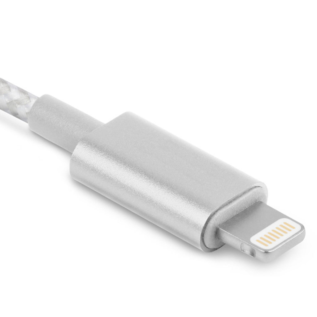
Lightning (8Pin)
Имеет прямоугольную форму, небольшие углубления по бокам и по 8 пар «дорожек» снизу/сверху
Как выглядят коннекторы для магнитных кабелей зарядки соответствующего типа
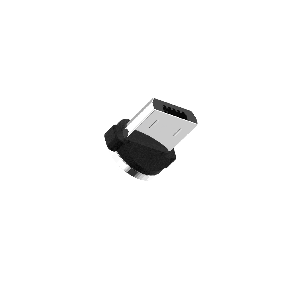
MicroUSB
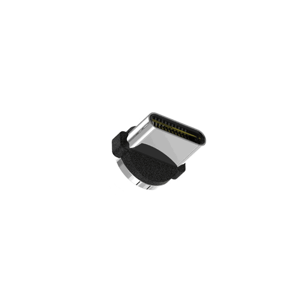
USB Type-C
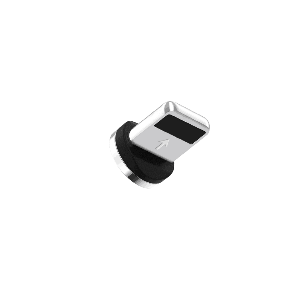
Lightning (8Pin)
О чем это вообще
Наверняка многие из вас никогда не задавались этим вопросом, так как мы получаем USB-шнурок для зарядки смарфтонов, планшетов, электронных сигарет и прочих гаджетов в комплекте с самим устройством. Тип коннектора Вашего кабеля зарядки ожидаемо совпадает с типом разъёма зарядного устройства гаджета и вам, по сути, неважно MicroUSB, Type-C это или же Apple Lightning (он же 8Pin). И если с Apple устройствами в виду унификации разъёма во всей портативной технике выпускаемой с 2012 года всё предельно просто и однозначно, то разные другие устройства используют два возможных типа разъёма ЗУ: MicroUSB или USB Type-C.
Здесь стоит отметить, что все три интерфейса не совместимы между собой, другими словами, MicroUSB кабель или же MicroUSB коннектор магнитного кабеля, просто не «войдет» в USB Type-C разъём, и наоборот, вам не удастся вставить коннектор USB Type-C кабеля в MicroUSB разъём. То самое касается Apple Lightning интерфейса, он так же не совместим с двумя предыдущими «героями».
Порой люди путают эти типы разъёмов или попросту не знают данной детали. Но как только человек приходит к выбору и покупке магнитного кабеля зарядки, сразу же возникает вопрос – какой тип коннектора в моем устройстве, что выбрать, чтобы не купить бесполезную вещь?
This article is about the physical and electrical aspects of USB connectors. For the standard in general, see USB.
Various USB connectors along a centimeter ruler for scale. From left to right:
- Micro-B plug
- 8-pin Mini-B plug, a proprietary connector used on many older Japanese cameras for both USB and analog AV output (This strongly resembles the 8-pin Micro-B plug which often has only 5 pin positions occupied.)
- Mini-B plug
- Type-A receptacle (inverted, so the contacts are visible)
- Type-A plug
- Type-B plug
The initial versions of the USB standard specified connectors that were easy to use and that would have acceptable life spans; revisions of the standard added smaller connectors useful for compact portable devices. Higher-speed development of the USB standard gave rise to another family of connectors to permit additional data paths. All versions of USB specify cable properties; version 3.x cables include additional data paths. The USB standard included power supply to peripheral devices; modern versions of the standard extend the power delivery limits for battery charging and devices requiring up to 100 watts. USB has been selected as the standard charging format for many mobile phones, reducing the proliferation of proprietary chargers.
Connectors[edit]

Comparison of USB connector plugs, excluding USB-C type plugs
The three sizes of USB connectors are the default or standard format intended for desktop or portable equipment, the mini intended for mobile equipment, which was deprecated when it was replaced by the thinner micro size, all of which were deprecated with the release of Type-C. There are five speeds for USB data transfer: Low Speed, Full Speed, High Speed (from version 2.0 of the specification), SuperSpeed (from version 3.0), and SuperSpeed+ (from version 3.1). The modes have differing hardware and cabling requirements. USB devices have some choice of implemented modes, and USB version is not a reliable statement of implemented modes. Modes are identified by their names and icons, and the specification suggests that plugs and receptacles be colour-coded (SuperSpeed is identified by blue).
Unlike other data buses (such as Ethernet), USB connections are directed; a host device has «downstream» facing ports that connect to the «upstream» facing ports of devices. Only downstream facing ports provide power; this topology was chosen to easily prevent electrical overloads and damaged equipment. Thus, USB cables have different ends: A and B, with different physical connectors for each. Each format has a plug and receptacle defined for each of the A and B ends. A USB cable, by definition, has a plug on each end—one A (or C) and one B (or C)—and the corresponding receptacle is usually on a computer or electronic device. The mini and micro formats may connect to an AB receptacle, which accepts either an A or a B plug, that plug determining the behavior of the receptacle.
Connector properties[edit]
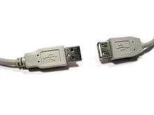
USB extension cable, plug on the left, receptacle (nonstandard, receptacles normally not allowed on cables) on the right
The connectors the USB committee specifies support a number of USB’s underlying goals, and reflect lessons learned from the many connectors the computer industry has used. The connector mounted on the host or device is called the receptacle, and the connector attached to the cable is called the plug.[1] The official USB specification documents also periodically define the term male to represent the plug, and female to represent the receptacle, though these uses are inconsistent with established definitions of connector gender.[2]
By design, it is difficult to insert a USB plug into its receptacle incorrectly. The USB specification requires that the cable plug and receptacle be marked so the user can recognize the proper orientation.[1] The USB-C plug however is reversible. USB cables and small USB devices are held in place by the gripping force from the receptacle, with no screws, clips, or thumb-turns as other connectors use.
The different A and B plugs prevent accidentally connecting two power sources. However, some of this directed topology is lost with the advent of multi-purpose USB connections (such as USB On-The-Go in smartphones, and USB-powered Wi-Fi routers), which require A-to-A, B-to-B, and sometimes Y/splitter cables. See the USB On-The-Go connectors section below for a more detailed summary description.
There are so-called cables with A plugs on both ends, which may be valid if the «cable» includes, for example, a USB host-to-host transfer device with two ports.[3] This is, by definition, a device with two logical B ports, each with a captive cable, not a cable with two A ends.
Durability[edit]
The standard connectors were designed to be more robust than many past connectors. This is because USB is hot-swappable, and the connectors would be used more frequently, and perhaps with less care, than previous connectors.
Standard USB has a minimum rated lifetime of 1,500 cycles of insertion and removal,[4] the mini-USB receptacle increases this to 5,000 cycles,[4] and the newer Micro-USB[4] and USB-C receptacles are both designed for a minimum rated lifetime of 10,000 cycles of insertion and removal.[5] To accomplish this, a locking device was added and the leaf-spring was moved from the jack to the plug, so that the most-stressed part is on the cable side of the connection. This change was made so that the connector on the less expensive cable would bear the most wear.[6][4]
In standard USB, the electrical contacts in a USB connector are protected by an adjacent plastic tongue, and the entire connecting assembly is usually protected by an enclosing metal shell.[4]
The shell on the plug makes contact with the receptacle before any of the internal pins. The shell is typically grounded, to dissipate static electricity and to shield the wires within the connector.
Compatibility[edit]
The USB standard specifies tolerances for compliant USB connectors to minimize physical incompatibilities in connectors from different vendors. The USB specification also defines limits to the size of a connecting device in the area around its plug, so that adjacent ports are not blocked. Compliant devices must either fit within the size restrictions or support a compliant extension cable that does.
Pinouts[edit]
USB 2.0 uses two wires for power (VBUS and GND), and two for differential serial data signals. Mini and micro connectors have their GND connections moved from pin #4 to pin #5, while their pin #4 serves as an ID pin for the On-The-Go host/client identification.[7]
USB 3.0 provides two additional differential pairs (four wires, SSTx+, SSTx−, SSRx+ and SSRx−), providing full-duplex data transfers at SuperSpeed, which makes it similar to Serial ATA or single-lane PCI Express.

Standard, Mini-, and Micro-USB plugs shown end-on, not to scale. Light areas represent cavities. The plugs are pictured with USB logo to the top.[8]

Micro-B SuperSpeed plug
- Power (VBUS, 5 V)
- Data− (D−)
- Data+ (D+)
- ID (On-The-Go)
- GND
- SuperSpeed transmit− (SSTx−)
- SuperSpeed transmit+ (SSTx+)
- GND
- SuperSpeed receive− (SSRx−)
- SuperSpeed receive+ (SSRx+)
| Pin | Name | Wire color[a] | Description | |
|---|---|---|---|---|
| 1 | VBUS | Red or | Orange | +5 V |
| 2 | D− | White or | Gold | Data− |
| 3 | D+ | Green | Data+ | |
| 4 | GND | Black or | Blue | Ground |
| Pin | Name | Wire color[a] | Description |
|---|---|---|---|
| 1 | VBUS | Red | +5 V |
| 2 | D− | White | Data− |
| 3 | D+ | Green | Data+ |
| 4 | ID | No wire | On-The-Go ID distinguishes cable ends:
|
| 5 | GND | Black | Signal ground |
- ^ a b In some sources D+ and D− are erroneously swapped.
Colors[edit]

A yellow charge-only USB port on a front panel USB 3.0 switch with card reader

A blue Standard-A USB connector without USB 3.0 contacts fitted
| Color | Location | Description | ||
|---|---|---|---|---|
| Black or white | Ports and plugs | Type-A or type-B | ||
| Blue (Pantone 300C) | Ports and plugs | Type-A or type-B, SuperSpeed | ||
| Teal blue | Ports and plugs | Type-A or type-B, SuperSpeed+ | ||
| Green | Ports and plugs | Type-A or type-B, Qualcomm Quick Charge (QC)[9] | ||
| Purple | Plugs only | Type-A or USB-C, Huawei SuperCharge | ||
| Yellow or red | Ports only | High-current or sleep-and-charge | ||
| Orange | Ports only | High-retention connector, mostly used on industrial hardware |
USB ports and connectors are often color-coded to distinguish their different functions and USB versions. These colors are not part of the USB specification and can vary between manufacturers; for example, USB 3.0 specification mandates appropriate color-coding while it only recommends blue inserts for standard-A USB 3.0 connectors and plugs.[10]
Connector types[edit]
USB connector types multiplied as the specification progressed. The original USB specification detailed standard-A and standard-B plugs and receptacles. The connectors were different so that users could not connect one computer receptacle to another. The data pins in the standard plugs are recessed compared to the power pins so that the device can power up before establishing a data connection. Some devices operate in different modes depending on whether the data connection is made. Charging docks supply power and do not include a host device or data pins, allowing any capable USB device to charge or operate from a standard USB cable. Charging cables provide power connections, but not data. In a charge-only cable, the data wires are shorted at the device end, otherwise, the device may reject the charger as unsuitable.
Standard connectors[edit]

Pin configuration of type-A and type-B plugs viewed end-on
- The type-A plug. This plug has an elongated rectangular cross-section, inserts into a type-A receptacle on a downstream port on a USB host or hub, and carries both power and data. Captive cables on USB devices, such as keyboards or mice, terminate with a type-A plug.
- The type-B plug: This plug has a near square cross-section with the top exterior corners beveled. As part of a removable cable, it inserts into an upstream port on a device, such as a printer. On some devices, the type-B receptacle has no data connections, being used solely for accepting power from the upstream device. This two-connector-type scheme (A/B) prevents a user from accidentally creating a loop.[11][12]
The maximum allowed cross-section of the overmold boot (which is part of the connector used for its handling) is 16 by 8 mm (0.63 by 0.31 in) for the standard-A plug type, while for the type-B it is 11.5 by 10.5 mm (0.45 by 0.41 in).[2]
Mini connectors[edit]
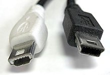
Mini-A (left) and Mini-B (right) plugs
Mini-USB connectors were introduced together with USB 2.0 in April 2000, for use with smaller devices such as digital cameras, smartphones, and tablet computers. The Mini-A connector and the Mini-AB receptacle connector have been deprecated since May 2007.[13] Mini-B connectors are still supported, but are not On-The-Go-compliant;[14] the Mini-B USB connector was standard for transferring data to and from the early smartphones and PDAs. Both Mini-A and Mini-B plugs are approximately 3 by 7 mm (0.12 by 0.28 in).
Micro connectors[edit]

Micro-A plug

Micro-B plug
Micro-USB connectors, which were announced by the USB-IF on 4 January 2007,[15][16] have a similar width to Mini-USB, but approximately half the thickness, enabling their integration into thinner portable devices. The Micro-A connector is 6.85 by 1.8 mm (0.270 by 0.071 in) with a maximum overmold boot size of 11.7 by 8.5 mm (0.46 by 0.33 in), while the Micro-B connector is 6.85 by 1.8 mm (0.270 by 0.071 in) with a maximum overmold size of 10.6 by 8.5 mm (0.42 by 0.33 in).[8]
The thinner Micro-USB connectors were intended to replace the Mini connectors in devices manufactured since May 2007, including smartphones, personal digital assistants, and cameras.[17]
The Micro plug design is rated for at least 10,000 connect-disconnect cycles, which is more than the Mini plug design.[15][18] The Micro connector is also designed to reduce the mechanical wear on the device; instead, the easier-to-replace cable is designed to bear the mechanical wear of connection and disconnection. The Universal Serial Bus Micro-USB Cables and Connectors Specification details the mechanical characteristics of Micro-A plugs, Micro-AB receptacles (which accept both Micro-A and Micro-B plugs), Double-Sided Micro USB, and Micro-B plugs and receptacles,[18] along with a Standard-A receptacle to a Micro-A plug adapter.
OMTP standard[edit]
Micro-USB was endorsed as the standard connector for data and power on mobile devices by the cellular phone carrier group Open Mobile Terminal Platform (OMTP) in 2007.[19]
Micro-USB was embraced as the «Universal Charging Solution» by the International Telecommunication Union (ITU) in October 2009.[20]
In Europe, micro-USB became the defined common external power supply (EPS) for use with smartphones sold in the EU,[21] and 14 of the world’s largest mobile phone manufacturers signed the EU’s common EPS Memorandum of Understanding (MoU).[22][23] Apple, one of the original MoU signers, makes Micro-USB adapters available—as permitted in the Common EPS MoU—for its iPhones equipped with Apple’s proprietary 30-pin dock connector or (later) Lightning connector.[24][25] according to the CEN, CENELEC, and ETSI.
USB 3.x connectors and backward compatibility[edit]
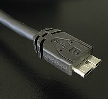
USB 3.0 Micro-B SuperSpeed plug
USB 3.0 introduced Type-A SuperSpeed plugs and receptacles as well as micro-sized Type-B SuperSpeed plugs and receptacles. The 3.0 receptacles are backward-compatible with the corresponding pre-3.0 plugs.
USB 3.x and USB 1.x Type-A plugs and receptacles are designed to interoperate. To achieve USB 3.0’s SuperSpeed (and SuperSpeed+ for USB 3.1 Gen 2), 5 extra pins are added to the unused area of the original 4 pin USB 1.0 design, making USB 3.0 Type-A plugs and receptacles backward compatible to those of USB 1.0.
On the device side, a modified Micro-B plug (Micro-B SuperSpeed) is used to cater for the five additional pins required to achieve the USB 3.0 features (USB-C plug can also be used). The USB 3.0 Micro-B plug effectively consists of a standard USB 2.0 Micro-B cable plug, with an additional 5 pins plug «stacked» to the side of it. In this way, cables with smaller 5 pin USB 2.0 Micro-B plugs can be plugged into devices with 10 contact USB 3.0 Micro-B receptacles and achieve backward compatibility.
USB cables exist with various combinations of plugs on each end of the cable, as displayed below in the USB cables matrix.

USB On-The-Go connectors[edit]
USB On-The-Go (OTG) introduces the concept of a device performing both master and slave roles. All current OTG devices are required to have one, and only one, USB connector: a Micro-AB receptacle. (In the past, before the development of Micro-USB, On-The-Go devices used Mini-AB receptacles).
The Micro-AB receptacle is capable of accepting both Micro-A and Micro-B plugs, attached to any of the legal cables and adapters as defined in revision 1.01 of the Micro-USB specification.
To enable Type-AB receptacles to distinguish which end of a cable is plugged in, plugs have an «ID» pin in addition to the four contacts in standard-size USB connectors. This ID pin is connected to GND in Type-A plugs, and left unconnected in Type-B plugs. Typically, a pull-up resistor in the device is used to detect the presence or absence of an ID connection.
The OTG device with the A-plug inserted is called the A-device and is responsible for powering the USB interface when required, and by default assumes the role of host. The OTG device with the B-plug inserted is called the B-device and by default assumes the role of peripheral. An OTG device with no plug inserted defaults to acting as a B-device. If an application on the B-device requires the role of host, then the Host Negotiation Protocol (HNP) is used to temporarily transfer the host role to the B-device.
OTG devices attached either to a peripheral-only B-device or a standard/embedded host have their role fixed by the cable, since in these scenarios it is only possible to attach the cable one way.[citation needed]
USB-C[edit]
![]()

USB cable with a USB-C plug and a USB-C port on a laptop
Developed at roughly the same time as the USB 3.1 specification, but distinct from it, the USB-C Specification 1.0 was finalized in August 2014[26] and defines a new small reversible-plug connector for USB devices.[27] The USB-C plug connects to both hosts and devices, replacing various Type-A and Type-B connectors and cables with a standard meant to be future-proof.[26][28]
The 24-pin double-sided connector provides four power–ground pairs, two differential pairs for USB 2.0 data (though only one pair is implemented in a USB-C cable), four pairs for SuperSpeed data bus (only two pairs are used in USB 3.1 mode), two «sideband use» pins, VCONN +5 V power for active cables, and a configuration pin for cable orientation detection and dedicated biphase mark code (BMC) configuration data channel.[29][30] Type-A and Type-B adaptors and cables are required for older hosts and devices to plug into USB-C hosts and devices. Adapters and cables with a USB-C receptacle are not allowed.[31]
Full-featured USB-C 3.1 cables are electronically marked cables that contain a full set of wires and a chip with an ID function based on the configuration data channel and vendor-defined messages (VDMs) from the USB Power Delivery 2.0 specification. USB-C devices also support power currents of 1.5 A and 3.0 A over the 5 V power bus in addition to baseline 900 mA; devices can either negotiate increased USB current through the configuration line or they can support the full Power Delivery specification using both BMC-coded configuration line and legacy BFSK-coded VBUS line.[citation needed]
Host and device interface receptacles[edit]
USB plugs fit one receptacle with notable exceptions for USB On-The-Go «AB» support and the general backward compatibility of USB 3.0 as shown.
| Plug Receptacle | USB A | USB 3.0 A SS | USB B | USB 3.0 B SS | USB Mini-A | USB Mini-B | USB Micro-A1 | USB Micro-B | USB 3.0 Micro-B | USB-C
|
|---|---|---|---|---|---|---|---|---|---|---|
USB A | Yes | Only non- SuperSpeed | No | No | No | No | No | No | No | No |
USB 3.0 A SS | Only non- SuperSpeed | Yes | No | No | No | No | No | No | No | No |
USB B | No | No | Yes | No | No | No | No | No | No | No |
USB 3.0 B SS | No | No | Only non- SuperSpeed | Yes | No | No | No | No | No | No |
| USB Mini-A | No | No | No | No | Yes | No | No | No | No | No |
| USB Mini-AB | No | No | No | No | Deprecated | Deprecated | No | No | No | No |
| USB Mini-B | No | No | No | No | No | Yes | No | No | No | No |
| USB Micro-AB | No | No | No | No | No | No | Yes | Yes | No | No |
| USB Micro-B | No | No | No | No | No | No | No | Yes | No | No |
| USB 3.0 Micro-B SS | No | No | No | No | No | No | No | Only non- SuperSpeed | Yes | No |
| USB-C
| No | No | No | No | No | No | No | No | No | Yes |
| ^1 No corresponding Micro-A receptacle was ever designed. |
| Plugs, each end | USB A | USB Mini-A | USB Micro-A | USB B | USB Mini-B | USB Micro-B | USB 3.0 Micro-B | USB-C
|
|---|---|---|---|---|---|---|---|---|
USB A | Proprietary, hazardous | Proprietary, hazardous | Proprietary, hazardous | Yes | Yes | Yes | Yes | Yes |
USB Mini-A | Proprietary, hazardous | No | No | Deprecated | Deprecated | Non- standard | No | No |
USB Micro-A | Proprietary, hazardous | No | No | Non- standard | Non- standard | Yes | No | No |
USB B | Yes | Deprecated | Non- standard | No | No | No | No | Yes |
USB Mini-B | Yes | Deprecated | Non- standard | No | OTG non- standard | OTG non- standard | No | Yes |
USB Micro-B | Yes | Non- standard | Yes | No | OTG non- standard | OTG non- standard | No | Yes |
USB 3.0 Micro-B | Yes | No | No | No | No | No | OTG non- standard | Yes |
| USB-C
| Yes | No | No | Yes | Yes | Yes | Yes | Yes |
- Proprietary, hazardous
- Existing for specific proprietary purposes, not inter-operable with USB-IF compliant equipment and possibly damaging to both devices when plugged in. In addition to the above cable assemblies comprising two plugs, an «adapter» cable with a Micro-A plug and a standard-A receptacle is compliant with USB specifications.[8] Other combinations of connectors are not compliant.There do exist A-to-A assemblies, referred to as cables (such as the Easy Transfer Cable); however, these have a pair of USB devices in the middle, making them more than just cables.
- Non-standard
- The USB standards do not exhaustively list all combinations with one A-type and one B-type connector, however, most such cables have good chances of working.
- OTG non-standard
- Commonly available «OTG» cables that address widespread misuse of Micro-B and Mini-B receptacles for OTG devices, e.g. smartphones (as opposed to Micro-AB and Mini-AB, which accept either plug.) While not compliant with the USB standards, these cables at least do not provide a device damage hazard since B-type ports on devices are unpowered by default.[32]
- Deprecated
- Some older devices and cables with Mini-A connectors have been certified by USB-IF. The Mini-A connector is obsolete: no new Mini-A connectors and neither Mini-A nor Mini-AB receptacles will be certified.[13]Note: Mini-B is not deprecated, although it is less and less used since the arrival of Micro-B. Micro-B is not the same as USB type B. Micro-B has one more wire than USB type B.
Proprietary connectors and formats[edit]
Manufacturers of personal electronic devices might not include a USB standard connector on their product for technical or marketing reasons.[33] Some manufacturers such as Apple provide proprietary cables that permit their devices to physically connect to a USB standard port. Full functionality of proprietary ports and cables with USB standard ports is not assured; for example, some devices only use the USB connection for battery charging and do not implement any data transfer functions.[34]
Cabling[edit]
![]()
A USB twisted pair, in which the Data+ and Data− conductors are twisted together in a double helix. The wires are enclosed in a further layer of shielding.
The D± signals used by low, full, and high speed are carried over a twisted pair (typically unshielded) to reduce noise and crosstalk. SuperSpeed uses separate transmit and receive differential pairs, which additionally require shielding (typically, shielded twisted pair but twinax is also mentioned by the specification). Thus, to support SuperSpeed data transmission, cables contain twice as many wires and are thus larger in diameter.[35]
The USB 1.1 standard specifies that a standard cable can have a maximum length of 5 meters (16 ft 5 in) with devices operating at full speed (12 Mbit/s), and a maximum length of 3 meters (9 ft 10 in) with devices operating at low speed (1.5 Mbit/s).[36][37][38]
USB 2.0 provides for a maximum cable length of 5 meters (16 ft 5 in) for devices running at high speed (480 Mbit/s). The primary reason for this limit is the maximum allowed round-trip delay of about 1.5 μs. If USB host commands are unanswered by the USB device within the allowed time, the host considers the command lost. When adding USB device response time, delays from the maximum number of hubs added to the delays from connecting cables, the maximum acceptable delay per cable amounts to 26 ns.[39] The USB 2.0 specification requires that cable delay be less than 5.2 ns/m (1.6 ns/ft, 192000 km/s), which is close to the maximum achievable transmission speed for standard copper wire.
The USB 3.0 standard does not directly specify a maximum cable length, requiring only that all cables meet an electrical specification: for copper cabling with AWG 26 wires the maximum practical length is 3 meters (9 ft 10 in).[40]
Power[edit]
Upstream USB connectors supply power at a nominal 5 V DC via the V_BUS pin to downstream USB devices.
Voltage tolerance and limits[edit]

Worst-case voltage drop topology of a USB 2.0 host to low-power device chain, at steady state
The tolerance on V_BUS at an upstream (or host) connector was originally ±5% (ie. could lie anywhere in the range 4.75 V to 5.25 V). With the release of the USB Type-C specification in 2014 and its 3 A power capability, the USB-IF elected to increase the upper voltage limit to 5.5 V to combat voltage droop at higher currents.[41] The USB 2.0 specification (and therefore implicitly also the USB 3.x specifications) was also updated to reflect this change at that time.[42] A number of extensions to the USB Specifications have progressively further increased the maximum allowable V_BUS voltage: starting with 6.0V with USB BC 1.2,[43] to 21.5 V with USB PD 2.0[44] and 50.9 V with USB PD 3.1,[44] while still maintaining backwards compatibility with USB 2.0 by requiring various forms of handshake before increasing the nominal voltage above 5 V.
USB PD continues the use of the bilateral 5% tolerance, with allowable voltages of PDO ±5% ±0.5 V (eg. for a PDO of 9.0 V, the maximum and minimum limits are 9.95 V and 8.05 V, respectively).[44]
There are several minimum allowable voltages defined at different locations within a chain of connectors, hubs, and cables between an upstream host (providing the power) and a downstream device (consuming the power). To allow for voltage drops, the voltage at the host port, hub port, and device are specified to be at least 4.75 V, 4.4 V, and 4.35 V respectively by USB 2.0 for low-power devices,[a] but must be at least 4.75 V at all locations for high-power[b] devices (however, high-power devices are required to operate as a low-powered device so that they may be detected and enumerated if connected to a low-power upstream port). The USB 3.x specifications require that all devices must operate down to 4.00 V at the device port.
Unlike USB 2.0 and USB 3.2, USB4 does not define its own VBUS-based power model. Power for USB4 operation is established and managed as defined in the USB Type-C Specification and the USB PD Specification.
- ^ Low-power devices are those which draw less than 1 unit load. 1 unit load is 100 mA for USB 2.0
- ^ High-power devices in USB 2.0 are those draw more than one unit load (up to a maximum of 5 unit loads). 1 unit load is 100mA.

Worst-case voltage drop topology of a USB 3.x host to device chain, at steady state. Note that under transient conditions the supply at the device can momentarily drop from 4.0 V to 3.67 V.
Allowable current draw[edit]
| Specification | Current | Voltage | Power (max.) |
|---|---|---|---|
| Low-power device | 100 mA | 5 V | 0.50 W |
| Low-power SuperSpeed (USB 3.0) device | 150 mA | 5 V | 0.75 W |
| High-power device | 500 mA[a] | 5 V | 2.5 W |
| High-power SuperSpeed (USB 3.0) device | 900 mA[b] | 5 V | 4.5 W |
| Multi-lane SuperSpeed (USB 3.2 Gen x2) device | 1.5 A[c] | 5 V | 7.5 W |
| Battery Charging (BC) 1.2 | 1.5 A | 5 V | 7.5 W |
| USB-C | 1.5 A | 5 V | 7.5 W |
| 3 A | 5 V | 15 W | |
| Power Delivery 1.0/2.0/3.0 Type-C | 5 A[d] | 20 V | 100 W |
| Power Delivery 3.1 Type-C | 5 A[d] | 48 V[e] | 240 W |
|
The limit to device power draw is stated in terms of a unit load which is 100 mA for USB 2.0, or 150 mA for SuperSpeed (ie USB 3.x) devices. Low-power devices may draw at most 1 unit load, and all devices must act as low-power devices before they are configured. A high-powered device must be configured, after which it may draw up to 5 unit loads (500 mA), or 6 unit loads (900 mA) for SuperSpeed devices, as specified in its configuration because the maximum power may not always be available from the upstream port.[45][46][47][48]
A bus-powered hub is a high-power device providing low-power ports. It draws 1 unit load for the hub controller and 1 unit load for each of at most 4 ports. The hub may also have some non-removable functions in place of ports. A self-powered hub is a device that provides high-power ports by supplementing the power supply from the host with its own external supply. Optionally, the hub controller may draw power for its operation as a low-power device, but all high-power ports must draw from the hub’s self-power.
Where devices (for example, high-speed disk drives) require more power than a high-power device can draw,[49] they function erratically, if at all, from bus power of a single port. USB provides for these devices as being self-powered. However, such devices may come with a Y-shaped cable that has two USB plugs (one for power and data, the other for only power), so as to draw power as two devices.[50] Such a cable is non-standard, with the USB compliance specification stating that «use of a ‘Y’ cable (a cable with two A-plugs) is prohibited on any USB peripheral», meaning that «if a USB peripheral requires more power than allowed by the USB specification to which it is designed, then it must be self-powered.»[51]
USB battery charging[edit]
USB Battery Charging (BC) defines a charging port, which may be a charging downstream port (CDP), with data, or a dedicated charging port (DCP) without data. Dedicated charging ports can be found on USB power adapters to run attached devices and battery packs. Charging ports on a host with both kinds will be labelled.[52]
The charging device identifies a charging port by non-data signaling on the D+ and D− terminals. A dedicated charging port places a resistance not exceeding 200 Ω across the D+ and D− terminals.[52]: § 1.4.7; table 5-3
Per the base specification, any device attached to a standard downstream port (SDP) must initially be a low-power device, with high-power mode contingent on later USB configuration by the host. Charging ports, however, can immediately supply between 0.5 and 1.5 A of current. The charging port must not apply current limiting below 0.5 A, and must not shut down below 1.5 A or before the voltage drops to 2 V.[52]
Since these currents are larger than in the original standard, the extra voltage drop in the cable reduces noise margins, causing problems with High Speed signaling. Battery Charging Specification 1.1 specifies that charging devices must dynamically limit bus power current draw during High Speed signaling;[53] 1.2 specifies that charging devices and ports must be designed to tolerate the higher ground voltage difference in High Speed signaling.
Revision 1.2 of the specification was released in 2010. It made several changes, and increased limits including allowing 1.5 A on charging downstream ports for unconfigured devices—allowing High Speed communication while having a current up to 1.5 A. Also, support was removed for charging port detection via resistive mechanisms.[54]
Before the Battery Charging Specification was defined, there was no standardized way for the portable device to inquire how much current was available. For example, Apple’s iPod and iPhone chargers indicate the available current by voltages on the D− and D+ lines. When D+ = D− = 2.0 V, the device may pull up to 900 mA. When D+ = 2.0 V and D− = 2.8 V, the device may pull up to 1 A of current.[55] When D+ = 2.8 V and D− = 2.0 V, the device may pull up to 2 A of current.[56]
Accessory charging adaptors (ACA)[edit]
Portable devices having a USB On-The-Go port may want to charge and access a USB peripheral simultaneously, yet having only a single port (both due to On-The-Go and space requirement) prevents this. Accessory charging adapters (ACA) are devices that provide portable charging power to an On-The-Go connection between host and peripheral.
ACAs have three ports: the OTG port for the portable device, which is required to have a Micro-A plug on a captive cable; the accessory port, which is required to have a Micro-AB or type-A receptacle; and the charging port, which is required to have a Micro-B receptacle, or type-A plug or charger on a captive cable. The ID pin of the OTG port is not connected within plug as usual, but to the ACA itself, where signals outside the OTG floating and ground states are used for ACA detection and state signaling. The charging port does not pass data, but does use the D± signals for charging port detection. The accessory port acts as any other port. When appropriately signaled by the ACA, the portable device can charge from the bus power as if there were a charging port present; any OTG signals over bus power are instead passed to the portable device via the ID signal. Bus power is also provided to the accessory port from the charging port transparently.[52]
USB Power Delivery[edit]
![]()
The USB Type-C Charging logo (USB4 20Gbps port)
| Profile | +5 V | +12 V | +20 V |
|---|---|---|---|
| 0 | Reserved | ||
| 1 | 2.0 A, 10 W[a] | — | — |
| 2 | 1.5 A, 18 W | ||
| 3 | 3.0 A, 36 W | ||
| 4 | 3.0 A, 60 W | ||
| 5 | 5.0 A, 60 W | 5.0 A, 100 W | |
|
| Source output power rating (W) | Current (A), at: | |||||||
|---|---|---|---|---|---|---|---|---|
| +5 V | +9 V | +15 V | +20 V | +28 V[A] | +36 V[A] | +48 V[A] | ||
| Standard Power Range (SPR)[58][59][60] | 0.5–15 | 0.1–3.0 | — | — | — | — | — | — |
| 15–27 | 3.0 (15 W) | 1.67–3.0 | ||||||
| 27–45 | 3.0 (27 W) | 1.8–3.0 | ||||||
| 45–60 | 3.0 (45 W) | 2.25–3.0 | ||||||
| 60–100 | 3.0–5.0[B] | |||||||
| Extended Power Range (EPR)[60] | 100–140 | 3.0 (60 W), 5.0 (100 W)[B] | 3.57–5.0 | |||||
| 140–180 | 5.0 (140 W) | 3.89–5.0 | ||||||
| 180–240 | 5.0 (180 W) | 3.75–5.0 | ||||||
|

Power rule of USB Power Delivery Revision 3.0, Version 1.2
In July 2012, the USB Promoters Group announced the finalization of the USB Power Delivery (USB-PD) specification (USB PD rev. 1), an extension that specifies using certified PD aware USB cables with standard USB Type-A and Type-B connectors to deliver increased power (more than 7.5 W) to devices with greater power demands. (USB-PD A and B plugs have a mechanical mark while Micro plugs have a resistor or capacitor attached to the ID pin indicating the cable capability.) USB-PD Devices can request higher currents and supply voltages from compliant hosts—up to 2 A at 5 V (for a power consumption of up to 10 W), and optionally up to 3 A or 5 A at either 12 V (36 W or 60 W) or 20 V (60 W or 100 W).[61] In all cases, both host-to-device and device-to-host configurations are supported.[62]
The intent is to permit uniformly charging laptops, tablets, USB-powered disks and similarly higher-power consumer electronics, as a natural extension of existing European and Chinese mobile telephone charging standards. This may also affect the way electric power used for small devices is transmitted and used in both residential and public buildings.[63][64] The standard is designed to coexist with the previous USB Battery Charging specification.[65]
The first Power Delivery specification defined six fixed power profiles for the power sources. PD-aware devices implement a flexible power management scheme by interfacing with the power source through a bidirectional data channel and requesting a certain level of electrical power, variable up to 5 A and 20 V depending on supported profile. The power configuration protocol can use BMC coding over the CC wire if one is present, or a 24 MHz BFSK-coded transmission channel on the VBUS line.
The USB Power Delivery specification revision 2.0 (USB PD Rev. 2.0) has been released as part of the USB 3.1 suite.[58][66][67] It covers the USB-C cable and connector with a separate configuration channel, which now hosts a DC coupled low-frequency BMC-coded data channel that reduces the possibilities for RF interference.[68] Power Delivery protocols have been updated to facilitate USB-C features such as cable ID function, Alternate Mode negotiation, increased VBUS currents, and VCONN-powered accessories.
As of USB Power Delivery specification revision 2.0, version 1.2, the six fixed power profiles for power sources have been deprecated.[69] USB PD Power Rules replace power profiles, defining four normative voltage levels at 5 V, 9 V, 15 V, and 20 V. Instead of six fixed profiles, power supplies may support any maximum source output power from 0.5 W to 100 W.
The USB Power Delivery specification revision 3.0 defines an optional Programmable Power Supply (PPS) protocol that allows granular control over VBUS power, allowing a range of 3.3 to 21 V in 20 mV steps to facilitate constant-current or constant-voltage charging. Revision 3.0 also adds extended configuration messages and fast role swap and deprecates the BFSK protocol.[59][70][71]

The Certified USB Fast Charger logo for USB Type-C charging ports
On 8 January 2018 USB-IF announced «Certified USB Fast Charger» logo for chargers that use «Programmable Power Supply» (PPS) protocol from the USB Power Delivery 3.0 specification.[72]
In May 2021, the USB PD promoter group launched revision 3.1 of the specification.[60] Revision 3.1 adds Extended Power Range (EPR) mode which allows higher voltages of 28, 36, and 48 V, providing up to 240 W of power (48 V at 5 A), and the «Adjustable Voltage Supply» (AVS) protocol which allows specifying the voltage from a range of 15 to 48 V in 100 mV steps.[73][74] Higher voltages require electronically marked EPR cables that support 5 A operation and incorporate mechanical improvements required by the USB Type-C standard rev. 2.1; existing power modes are retroactively renamed Standard Power Range (SPR). In October 2021 Apple introduced a 140 W (28 V 5 A) GaN USB PD charger with new Macbooks.[75]
Prior to Power Delivery, mobile phone vendors used custom protocols to exceed the 7.5 W cap on USB-BCS. For example, Qualcomm’s Quick Charge 2.0 is able to deliver 18 W at a higher voltage, and VOOC delivers 20 W at the normal 5 V.[76] Some of these technologies, such as Quick Charge 4, eventually became compatible with USB PD again.[77]
Sleep-and-charge ports[edit]

A yellow USB port denoting sleep-and-charge
Sleep-and-charge USB ports can be used to charge electronic devices even when the computer that hosts the ports is switched off. Normally, when a computer is powered off the USB ports are powered down. This feature has also been implemented on some laptop docking stations allowing device charging even when no laptop is present.[78] On laptops, charging devices from the USB port when it is not being powered from AC drains the laptop battery; most laptops have a facility to stop charging if their own battery charge level gets too low.[79]
On Dell, HP and Toshiba laptops, sleep-and-charge USB ports are marked with the standard USB symbol with an added lightning bolt or battery icon on the right side.[80] Dell calls this feature PowerShare,[81] and it needs to be enabled in the BIOS. Toshiba calls it USB Sleep-and-Charge.[82] On Acer Inc. and Packard Bell laptops, sleep-and-charge USB ports are marked with a non-standard symbol (the letters USB over a drawing of a battery); the feature is called Power-off USB.[83] Lenovo calls this feature Always On USB.[84]
Mobile device charger standards[edit]
In China[edit]
As of 14 June 2007, all new mobile phones applying for a license in China are required to use a USB port as a power port for battery charging.[85][86] This was the first standard to use the convention of shorting D+ and D− in the charger.[87]
OMTP/GSMA Universal Charging Solution[edit]
In September 2007, the Open Mobile Terminal Platform group (a forum of mobile network operators and manufacturers such as Nokia, Samsung, Motorola, Sony Ericsson, and LG) announced that its members had agreed on Micro-USB as the future common connector for mobile devices.[88][89]
The GSM Association (GSMA) followed suit on 17 February 2009,[90][91][92][93] and on 22 April 2009, this was further endorsed by the CTIA – The Wireless Association,[94] with the International Telecommunication Union (ITU) announcing on 22 October 2009 that it had also embraced the Universal Charging Solution as its «energy-efficient one-charger-fits-all new mobile phone solution,» and added: «Based on the Micro-USB interface, UCS chargers will also include a 4-star or higher efficiency rating—up to three times more energy-efficient than an unrated charger.»[95]
EU smartphone power supply standard[edit]
In June 2009, many of the world’s largest mobile phone manufacturers signed an EC-sponsored Memorandum of Understanding (MoU), agreeing to make most data-enabled mobile phones marketed in the European Union compatible with a common External Power Supply (common EPS). The EU’s common EPS specification (EN 62684:2010) references the USB Battery Charging Specification and is similar to the GSMA/OMTP and Chinese charging solutions.[96][97] In January 2011, the International Electrotechnical Commission (IEC) released its version of the (EU’s) common EPS standard as IEC 62684:2011.[98] The European Union and its members should adopt a resolution during 2022 for the global adoption of USB Type C chargers for all mobile products on the European market.[99]
Faster-charging standards[edit]
A variety of (non-USB) standards support charging devices faster than the USB Battery Charging standard. When a device doesn’t recognize the faster-charging standard, generally the device and the charger fall back to the USB battery-charging standard of 5 V at 1.5 A (7.5 W). When a device detects it is plugged into a charger with a compatible faster-charging standard, the device pulls more current or the device tells the charger to increase the voltage or both to increase power (the details vary between standards).[100]
Such standards include:[100][101]
- Qualcomm Quick Charge (QC)
- MediaTek Pump Express
- Samsung Adaptive Fast Charging
- Oppo Super VOOC Flash Charge, are also known as Dash Charge or Warp Charge on OnePlus devices and Dart Charge on Realme devices
- Huawei SuperCharge
- Anker PowerIQ
- Google fast charging
- Motorola TurboPower
Non-standard devices[edit]
Some USB devices require more power than is permitted by the specifications for a single port. This is common for external hard and optical disc drives, and generally for devices with motors or lamps. Such devices can use an external power supply, which is allowed by the standard, or use a dual-input USB cable, one input of which is for power and data transfer, the other solely for power, which makes the device a non-standard USB device. Some USB ports and external hubs can, in practice, supply more power to USB devices than required by the specification but a standard-compliant device may not depend on this.
In addition to limiting the total average power used by the device, the USB specification limits the inrush current (i.e., the current used to charge decoupling and filter capacitors) when the device is first connected. Otherwise, connecting a device could cause problems with the host’s internal power. USB devices are also required to automatically enter ultra low-power suspend mode when the USB host is suspended. Nevertheless, many USB host interfaces do not cut off the power supply to USB devices when they are suspended.[102]
Some non-standard USB devices use the 5 V power supply without participating in a proper USB network, which negotiates power draw with the host interface. Examples include USB-powered keyboard lights, fans, mug coolers and heaters, battery chargers, miniature vacuum cleaners, and even miniature lava lamps. In most cases, these items contain no digital circuitry, and thus are not standard-compliant USB devices. This may cause problems with some computers, such as drawing too much current and damaging circuitry. Prior to the USB Battery Charging Specification, the USB specification required that devices connect in a low-power mode (100 mA maximum) and communicate their current requirements to the host, which then permits the device to switch into high-power mode.
Some devices, when plugged into charging ports, draw even more power (10 watts at 2.1 amperes) than the Battery Charging Specification allows—the iPad is one such device;[103] it negotiates the current pull with data pin voltages.[55] Barnes & Noble Nook Color devices also require a special charger that runs at 1.9 amperes.[104]
PoweredUSB[edit]
PoweredUSB is a proprietary extension that adds four pins supplying up to 6 A at 5 V, 12 V, or 24 V. It is commonly used in point of sale systems to power peripherals such as barcode readers, credit card terminals, and printers.
See also[edit]
- USB (Communications)
- USB adapter
References[edit]
- ^ a b Universal Serial Bus 3.0 Specification: Revision 1.0. Contributors: Hewlett-Packard, Intel, Microsoft, NEC, ST-Ericsson, Texas Instruments. 6 June 2011. p. 531. Archived from the original on 30 December 2013. Retrieved 28 April 2019.
{{cite book}}: CS1 maint: others (link) - ^ a b «USB 2.0 Specification Engineering Change Notice (ECN) #1: Mini-B connector» (PDF). 20 October 2000. Archived from the original (PDF) on 12 April 2015. Retrieved 28 April 2019 – via www.usb.org.
- ^ «USB connector guide». C2G. Archived from the original on 21 April 2014. Retrieved 2 December 2013.
- ^ a b c d e «Universal Serial Bus Cables and Connectors Class Document Revision 2.0» (PDF). USB.org. August 2007. Archived from the original (PDF) on 11 June 2014. Retrieved 28 April 2019.
- ^ Howse, Brett. «USB Type-C Connector Specifications Finalized». AnandTech. Anadtech. Archived from the original on 18 March 2017. Retrieved 24 April 2017.
- ^ «Why was Mini-USB deprecated in favor of Micro-USB?». Stack exchange. 2011. Archived from the original on 7 December 2013. Retrieved 3 December 2013.[unreliable source?]
- ^ «USB Pinout». usbpinout.net. Archived from the original on 17 June 2014. Retrieved 28 April 2019.
- ^ a b c «Universal Serial Bus Micro-USB Cables and Connectors Specification» (PDF). USB Implementers Forum. 2007-04-04. Archived (PDF) from the original on 2015-11-15. Retrieved 2015-01-31.
- ^ «Qualcomm Certified Nekteck Quick Charge 2.0 54W 4 Ports USB Rapid Turbo Car Charger». Amazon. Retrieved 19 July 2017.
- ^ «Universal Serial Bus Revision 3.0 Specification, Sections 3.1.1.1 and 5.3.1.3». usb.org. Archived from the original (ZIP) on 19 May 2014. Retrieved 28 April 2019.
- ^ Quinnell, Richard A (24 October 1996). «USB: a neat package with a few loose ends». EDN Magazine. Reed. Archived from the original on 23 May 2013. Retrieved 18 February 2013.
- ^ «What is the Difference between USB Type A and USB Type B Plug/Connector?». Archived from the original on 7 February 2017.
- ^ a b «Deprecation of the Mini-A and Mini-AB Connectors» (PDF) (Press release). USB Implementers Forum. 27 May 2007. Archived (PDF) from the original on 6 March 2009. Retrieved 13 January 2009.
- ^ «ID Pin Resistance on Mini B-plugs and Micro B-plugs Increased to 1 Mohm». USB IF Compliance Updates. December 2009. Archived from the original on 20 July 2011. Retrieved 1 March 2010.
- ^ a b Universal Serial Bus Cables and Connectors Class Document (PDF), Revision 2.0, USB Implementers Forum, August 2007, p. 6, archived (PDF) from the original on 27 April 2015, retrieved 17 August 2014
- ^ «Mobile phones to adopt new, smaller USB connector» (PDF) (Press release). USB Implementers Forum. 4 January 2007. Archived (PDF) from the original on 8 January 2007. Retrieved 8 January 2007.
- ^ «Micro-USB pinout and list of compatible smartphones and other devices». pinoutsguide.com. Archived from the original on 10 October 2013.
- ^ a b «Universal Serial Bus Micro-USB Cables and Connectors Specification to the USB 2.0 Specification, Revision 1.01». USB Implementers Forum. 7 April 2007. Archived from the original (Zip) on 7 February 2012. Retrieved 18 November 2010.
Section 1.3: Additional requirements for a more rugged connector that is durable past 10,000 cycles and still meets the USB 2.0 specification for mechanical and electrical performance was also a consideration. The Mini-USB could not be modified and remain backward compatible to the existing connector as defined in the USB OTG specification.
- ^ «OMTP Local Connectivity: Data Connectivity». Open Mobile Terminal Platform. 17 September 2007. Archived from the original on 15 October 2008. Retrieved 2009-02-11.
- ^ «Universal phone charger standard approved—One-size-fits-all solution will dramatically cut waste and GHG emissions». ITU (press release). Pressinfo. 22 October 2009. Archived from the original on 5 November 2009. Retrieved 4 November 2009.
- ^ «Commission welcomes new EU standards for common mobile phone charger». Press Releases. Europa. 29 December 2010. Archived from the original on 19 March 2011. Retrieved 22 May 2011.
- ^ New EU standards for common mobile phone charger (press release), Europa, archived from the original on 3 January 2011
- ^ The following 10 biggest mobile phone companies have signed the MoU: Apple, LG, Motorola, NEC, Nokia, Qualcomm, Research In Motion, Samsung, Sony Ericsson, Texas Instruments (press release), Europa, archived from the original on 2009-07-04
- ^ «Nice Micro-USB adapter Apple, now sell it everywhere», Giga om, 5 October 2011, archived from the original on 26 August 2012
- ^ «Apple’s Lightning to Micro-USB adapter now available in US, not just Europe anymore», Engadget, 3 November 2012, archived from the original on 26 June 2017
- ^ a b Howse, Brett (12 August 2014). «USB Type-C Connector Specifications Finalized». Archived from the original on 28 December 2014. Retrieved 28 December 2014.
- ^ Hruska, Joel (13 March 2015). «USB-C vs. USB 3.1: What’s the difference?». ExtremeTech. Archived from the original on 11 April 2015. Retrieved 9 April 2015.
- ^ Ngo, Dong (22 August 2014). «USB Type-C: One Cable to Connect Them All». c|net. Archived from the original on 2015-03-07. Retrieved 28 December 2014.
- ^ «Technical Introduction of the New USB Type-C Connector». Archived from the original on 29 December 2014. Retrieved 29 December 2014.
- ^ Smith, Ryan (22 September 2014). «DisplayPort Alternate Mode for USB Type-C Announced — Video, Power, & Data All Over Type-C». AnandTech. Archived from the original on 18 December 2014. Retrieved 28 December 2014.
- ^ Universal Serial Bus Type-C Cable and Connector Specification Revision 1.1 (April 3, 2015), section 2.2, page 20
- ^ «On-The-Go and Embedded Host Supplement to the USB Revision 3.0 Specification» (PDF). USB.org. Revision 1.1. May 10, 2012.
- ^ «Proprietary Cables vs Standard USB». anythingbutipod.com. 30 April 2008. Archived from the original on 13 November 2013. Retrieved 29 October 2013.
- ^ Lex Friedman (25 February 2013). «Review: Logitech’s Ultrathin mini keyboard cover makes the wrong tradeoffs». macworld.com. Archived from the original on 3 November 2013. Retrieved 29 October 2013.
- ^ «What is the USB 3.0 Cable Difference». Hantat. 18 May 2009. Archived from the original on 11 December 2011. Retrieved 12 December 2011.
- ^ «USB Cable Length Limitations» (PDF). cablesplususa.com. 3 November 2010. Archived from the original (PDF) on 11 October 2014. Retrieved 2 February 2014.
- ^ «What is the Maximum Length of a USB Cable?». Techwalla.com. Archived from the original on 1 December 2017. Retrieved 18 November 2017.
- ^ «Cables and Long-Haul Solutions». USB FAQ. USB.org. Archived from the original on 15 January 2014. Retrieved 2 February 2014.
- ^ «USB Frequently Asked Questions». USB Implementers Forum. Archived from the original on 18 January 2011. Retrieved 10 December 2010.
- ^ Axelson, Jan. «USB 3.0 Developers FAQ». Archived from the original on 20 December 2016. Retrieved 20 October 2016.
- ^ «USB Type-C Revision 1.0» (PDF). USB 3.0 Promoter Group. 2021-03-01. Archived (PDF) from the original on 2021-11-03. Retrieved 2021-11-03.
- ^ «USB ECN USB 2.0 VBUS Max Limit». USB-IF. 2021-11-03. Archived from the original on 2021-11-03. Retrieved 2021-11-03.
- ^ «Battery Charging v1.2 Spec and Adopters Agreement» (PDF (Zipped)). USB IF. 2015-03-15. Table 5-1 Voltages. Archived (PDF (Zipped)) from the original on 2021-11-03. Retrieved 2021-11-03.
- ^ a b c «USB Power Delivery Specifications 2.0 and 3.1» (PDF (Zipped)). USB IF. 2021-10-26. Archived (PDF (Zipped)) from the original on 2021-11-03. Retrieved 2021-11-03.
- ^ «USB.org». USB.org. Archived from the original on 19 June 2012. Retrieved 22 June 2010.
- ^ «Universal Serial Bus 1.1 Specification» (PDF). cs.ucr.edu. 23 September 1998. pp. 150, 158. Archived (PDF) from the original on 2 January 2015. Retrieved 24 November 2014.
- ^ «Universal Serial Bus 2.0 Specification, Section 7.2.1.3 Low-power Bus-powered Functions» (ZIP). usb.org. 27 April 2000. Archived from the original on 10 September 2013. Retrieved 11 January 2014.
- ^ «Universal Serial Bus 2.0 Specification, Section 7.2.1.4 High-power Bus-powered Functions» (ZIP). usb.org. 27 April 2000. Archived from the original on 10 September 2013. Retrieved 11 January 2014.
- ^ «Roundup: 2.5-inch Hard Disk Drives with 500 GB, 640 GB and 750 GB Storage Capacities (page 17)». xbitlabs.com. 16 June 2010. Archived from the original on 28 June 2010. Retrieved 9 July 2010.
- ^ «I have the drive plugged in but I cannot find the drive in «My Computer», why?». hitachigst.com. Archived from the original on 15 February 2011. Retrieved 30 March 2012.
- ^ «USB-IF Compliance Updates». Compliance.usb.org. 1 September 2011. Archived from the original on 3 February 2014. Retrieved 22 January 2014.
- ^ a b c d «Battery Charging Specification, Revision 1.2». USB Implementers Forum. 15 March 2012. Archived from the original on 10 March 2021. Retrieved 13 August 2021.
- ^ «Battery Charging Specification, Revision 1.1». USB Implementers Forum. 15 April 2009. Archived from the original on 29 March 2014. Retrieved 2009-09-23.
- ^ «Battery Charging v1.2 Spec and Adopters Agreement» (Zip). USB Implementers Forum. 15 March 2012. Archived from the original on 6 October 2014. Retrieved 13 May 2021.
- ^ a b «Minty Boost — The mysteries of Apple device charging». Lady Ada. 17 May 2011. Archived from the original on 28 March 2012.
- ^ «Modify a cheap USB charger to feed an iPod, iPhone». 5 October 2011. Archived from the original on 7 October 2011.
- ^ «PD_1.0» (PDF). Archived (PDF) from the original on 4 April 2016. Retrieved 27 April 2016.
- ^ a b «10 Power Rules», Universal Serial Bus Power Delivery Specification revision 2.0, version 1.2, USB Implementers Forum, 25 March 2016, archived from the original on 1 June 2012, retrieved 9 April 2016
- ^ a b «10 Power Rules», Universal Serial Bus Power Delivery Specification revision 3.0, version 1.1, USB Implementers Forum, archived from the original on 1 June 2012, retrieved 5 September 2017
- ^ a b c «10 Power Rules», Universal Serial Bus Power Delivery Specification revision 3.1, version 1.0, USB Implementers Forum, retrieved 5 September 2017
- ^ Burgess, Rick. «USB 3.0 SuperSpeed Update to Eliminate Need for Chargers». TechSpot.
- ^ «USB 3.0 Promoter Group Announces Availability of USB Power Delivery Specification» (PDF). 18 July 2012. Archived (PDF) from the original on 20 January 2013. Retrieved 16 January 2013.
- ^ «Edison’s revenge». The Economist. 19 October 2013. Archived from the original on 22 October 2013. Retrieved 23 October 2013.
- ^ «USB Power Delivery — Introduction» (PDF). 16 July 2012. Archived (PDF) from the original on 23 January 2013. Retrieved 6 January 2013.
- ^ «USB Power Delivery».
- ^ «USB 3.1 Specification». Archived from the original on 19 June 2012. Retrieved 11 November 2014.
- ^ «USB Power Delivery v2.0 Specification Finalized — USB Gains Alternate Modes». AnandTech.com.
- ^ «USB Future Specifications Industry Reviews» (PDF). Archived (PDF) from the original on 29 July 2014. Retrieved 10 August 2014.
- ^ «A. Power Profiles», Universal Serial Bus Power Delivery Specification revision 2.0, version 1.2, USB Implementers Forum, 25 March 2016, archived from the original on 12 April 2016, retrieved 9 April 2016
- ^ «USB Power Delivery» (PDF). usb.org. USB-IF. 20 October 2016. Archived from the original (PDF) on 20 December 2016.
- ^ Waters, Deric (14 July 2016). «USB Power Delivery 2.0 vs 3.0». E2E.TI.com. Archived from the original on 30 July 2017. Retrieved 30 July 2017.
- ^ «USB-IF Introduces Fast Charging to Expand its Certified USB Charger Initiative». 9 January 2018. Retrieved 10 January 2018.
- ^ USB-PD boosts USB-C power delivery to 240W at 48V. Nick Flaherty, EENews. May 28, 2021
- ^ USB-C Power Delivery Hits 240W with Extended Power Range. Ganesh T S, Anandtech. May 28, 2021
- ^ «Teardown of Brand New Apple 140W USB-C GaN Charger». Retrieved 15 November 2021.
- ^ «How fast can a fast-charging phone charge if a fast-charging phone can charge really fast?». CNet. Retrieved 2016-12-04.
- ^ «Qualcomm Announces Quick Charge 4: Supports USB Type-C Power Delivery». AnandTech. Retrieved 2016-12-13.
- ^ «ThinkPad Ultra Dock». lenovo.com. Archived from the original on 17 September 2016. Retrieved 16 September 2016.
- ^ «Toshiba NB200 User Manual» (PDF). UK. 1 March 2009. Archived (PDF) from the original on 19 February 2014. Retrieved 26 January 2014.
- ^ «USB PowerShare Feature». dell.com. 15 September 2019. Retrieved 15 June 2020.
- ^ «USB PowerShare Feature». dell.com. 5 June 2013. Archived from the original on 8 November 2013. Retrieved 4 December 2013.
- ^ «USB Sleep-and-Charge Ports». toshiba.com. Archived from the original on 14 December 2014. Retrieved 21 December 2014.
- ^ «USB Charge Manager». packardbell.com. Retrieved 2014-04-25.
- ^ «How to configure the system to charge devices over USB port when it is off — idea/Lenovo laptops — NL». support.lenovo.com. Retrieved 2020-04-07.
- ^ Cai Yan (31 May 2007). «China to enforce universal cell phone charger». EE Times. Archived from the original on 29 September 2007. Retrieved 25 August 2007.
- ^ The Chinese technical standard: «YD/T 1591-2006, Technical Requirements and Test Method of Charger and Interface for Mobile Telecommunication Terminal Equipment» (PDF) (in Chinese). Dian yuan. Archived from the original (PDF) on 15 May 2011.
- ^ Lam, Crystal; Liu, Harry (22 October 2007). «How to conform to China’s new mobile phone interface standards». Wireless Net DesignLine. Archived from the original on 14 May 2014. Retrieved 22 June 2010.
- ^ «Pros seem to outdo cons in new phone charger standard». News. 20 September 2007. Retrieved 2007-11-26.
- ^ «Broad Manufacturer Agreement Gives Universal Phone Cable Green Light» (Press release). OTMP. 17 September 2007. Archived from the original on 29 June 2009. Retrieved 26 November 2007.
- ^ «Agreement on Mobile phone Standard Charger» (Press release). GSM World. Archived from the original on 17 February 2009.
- ^ «Common Charging and Local Data Connectivity». Open Mobile Terminal Platform. 11 February 2009. Archived from the original on 29 March 2009. Retrieved 2009-02-11.
- ^ «Universal Charging Solution ~ GSM World». GSM world. Archived from the original on 26 June 2010. Retrieved 22 June 2010.
- ^ «Meeting the challenge of the universal charge standard in mobile phones». Planet Analog. Archived from the original on 2012-09-09. Retrieved 2010-06-22.
- ^ «The Wireless Association Announces One Universal Charger Solution to Celebrate Earth Day» (Press release). CTIA. 22 April 2009. Archived from the original on 14 December 2010. Retrieved 22 June 2010.
- ^ «ITU» (Press release). 22 October 2009. Archived from the original on 27 March 2010. Retrieved 22 June 2010.
- ^ «chargers». EU: EC. 29 June 2009. Archived from the original on 23 October 2009. Retrieved 22 June 2010.
- ^ «Europe gets universal cellphone charger in 2010». Wired. 13 June 2009. Archived from the original on 18 August 2010. Retrieved 22 June 2010.
- ^ «One size-fits-all mobile phone charger: IEC publishes first globally relevant standard». International Electrotechnical Commission. 1 February 2011. Archived from the original on 3 January 2012. Retrieved 20 February 2012.
- ^ «Common charger: MEPs agree on proposal to reduce electronic waste». European Parliament. 2022-04-20. Archived from the original on 2022-04-22. Retrieved 2022-04-20.
- ^ a b
Ajay Kumar.
«What Is Fast Charging?».
2018. - ^ Hill, Simon; Revilla, Andre; Chandler, Simon (1 July 2021). «How does fast charging work? Here’s every single standard compared». Digital Trends. Retrieved 20 August 2022.
- ^ «Part 2 — Electrical». MQP Electronics Ltd. Archived from the original on 24 December 2014. Retrieved 29 December 2014.
- ^ «Watt to Know About iPhone & iPad Power Adapters | Analysis». The Mac Observer. Archived from the original on 10 December 2011. Retrieved 12 December 2011.
- ^ «Nook Color charger uses special Micro-USB connector». barnesandnoble.com. 3 July 2011. Archived from the original on 11 February 2012.
This article is about the physical and electrical aspects of USB connectors. For the standard in general, see USB.
Various USB connectors along a centimeter ruler for scale. From left to right:
- Micro-B plug
- 8-pin Mini-B plug, a proprietary connector used on many older Japanese cameras for both USB and analog AV output (This strongly resembles the 8-pin Micro-B plug which often has only 5 pin positions occupied.)
- Mini-B plug
- Type-A receptacle (inverted, so the contacts are visible)
- Type-A plug
- Type-B plug
The initial versions of the USB standard specified connectors that were easy to use and that would have acceptable life spans; revisions of the standard added smaller connectors useful for compact portable devices. Higher-speed development of the USB standard gave rise to another family of connectors to permit additional data paths. All versions of USB specify cable properties; version 3.x cables include additional data paths. The USB standard included power supply to peripheral devices; modern versions of the standard extend the power delivery limits for battery charging and devices requiring up to 100 watts. USB has been selected as the standard charging format for many mobile phones, reducing the proliferation of proprietary chargers.
Connectors[edit]

Comparison of USB connector plugs, excluding USB-C type plugs
The three sizes of USB connectors are the default or standard format intended for desktop or portable equipment, the mini intended for mobile equipment, which was deprecated when it was replaced by the thinner micro size, all of which were deprecated with the release of Type-C. There are five speeds for USB data transfer: Low Speed, Full Speed, High Speed (from version 2.0 of the specification), SuperSpeed (from version 3.0), and SuperSpeed+ (from version 3.1). The modes have differing hardware and cabling requirements. USB devices have some choice of implemented modes, and USB version is not a reliable statement of implemented modes. Modes are identified by their names and icons, and the specification suggests that plugs and receptacles be colour-coded (SuperSpeed is identified by blue).
Unlike other data buses (such as Ethernet), USB connections are directed; a host device has «downstream» facing ports that connect to the «upstream» facing ports of devices. Only downstream facing ports provide power; this topology was chosen to easily prevent electrical overloads and damaged equipment. Thus, USB cables have different ends: A and B, with different physical connectors for each. Each format has a plug and receptacle defined for each of the A and B ends. A USB cable, by definition, has a plug on each end—one A (or C) and one B (or C)—and the corresponding receptacle is usually on a computer or electronic device. The mini and micro formats may connect to an AB receptacle, which accepts either an A or a B plug, that plug determining the behavior of the receptacle.
Connector properties[edit]

USB extension cable, plug on the left, receptacle (nonstandard, receptacles normally not allowed on cables) on the right
The connectors the USB committee specifies support a number of USB’s underlying goals, and reflect lessons learned from the many connectors the computer industry has used. The connector mounted on the host or device is called the receptacle, and the connector attached to the cable is called the plug.[1] The official USB specification documents also periodically define the term male to represent the plug, and female to represent the receptacle, though these uses are inconsistent with established definitions of connector gender.[2]
By design, it is difficult to insert a USB plug into its receptacle incorrectly. The USB specification requires that the cable plug and receptacle be marked so the user can recognize the proper orientation.[1] The USB-C plug however is reversible. USB cables and small USB devices are held in place by the gripping force from the receptacle, with no screws, clips, or thumb-turns as other connectors use.
The different A and B plugs prevent accidentally connecting two power sources. However, some of this directed topology is lost with the advent of multi-purpose USB connections (such as USB On-The-Go in smartphones, and USB-powered Wi-Fi routers), which require A-to-A, B-to-B, and sometimes Y/splitter cables. See the USB On-The-Go connectors section below for a more detailed summary description.
There are so-called cables with A plugs on both ends, which may be valid if the «cable» includes, for example, a USB host-to-host transfer device with two ports.[3] This is, by definition, a device with two logical B ports, each with a captive cable, not a cable with two A ends.
Durability[edit]
The standard connectors were designed to be more robust than many past connectors. This is because USB is hot-swappable, and the connectors would be used more frequently, and perhaps with less care, than previous connectors.
Standard USB has a minimum rated lifetime of 1,500 cycles of insertion and removal,[4] the mini-USB receptacle increases this to 5,000 cycles,[4] and the newer Micro-USB[4] and USB-C receptacles are both designed for a minimum rated lifetime of 10,000 cycles of insertion and removal.[5] To accomplish this, a locking device was added and the leaf-spring was moved from the jack to the plug, so that the most-stressed part is on the cable side of the connection. This change was made so that the connector on the less expensive cable would bear the most wear.[6][4]
In standard USB, the electrical contacts in a USB connector are protected by an adjacent plastic tongue, and the entire connecting assembly is usually protected by an enclosing metal shell.[4]
The shell on the plug makes contact with the receptacle before any of the internal pins. The shell is typically grounded, to dissipate static electricity and to shield the wires within the connector.
Compatibility[edit]
The USB standard specifies tolerances for compliant USB connectors to minimize physical incompatibilities in connectors from different vendors. The USB specification also defines limits to the size of a connecting device in the area around its plug, so that adjacent ports are not blocked. Compliant devices must either fit within the size restrictions or support a compliant extension cable that does.
Pinouts[edit]
USB 2.0 uses two wires for power (VBUS and GND), and two for differential serial data signals. Mini and micro connectors have their GND connections moved from pin #4 to pin #5, while their pin #4 serves as an ID pin for the On-The-Go host/client identification.[7]
USB 3.0 provides two additional differential pairs (four wires, SSTx+, SSTx−, SSRx+ and SSRx−), providing full-duplex data transfers at SuperSpeed, which makes it similar to Serial ATA or single-lane PCI Express.

Standard, Mini-, and Micro-USB plugs shown end-on, not to scale. Light areas represent cavities. The plugs are pictured with USB logo to the top.[8]

Micro-B SuperSpeed plug
- Power (VBUS, 5 V)
- Data− (D−)
- Data+ (D+)
- ID (On-The-Go)
- GND
- SuperSpeed transmit− (SSTx−)
- SuperSpeed transmit+ (SSTx+)
- GND
- SuperSpeed receive− (SSRx−)
- SuperSpeed receive+ (SSRx+)
| Pin | Name | Wire color[a] | Description | |
|---|---|---|---|---|
| 1 | VBUS | Red or | Orange | +5 V |
| 2 | D− | White or | Gold | Data− |
| 3 | D+ | Green | Data+ | |
| 4 | GND | Black or | Blue | Ground |
| Pin | Name | Wire color[a] | Description |
|---|---|---|---|
| 1 | VBUS | Red | +5 V |
| 2 | D− | White | Data− |
| 3 | D+ | Green | Data+ |
| 4 | ID | No wire | On-The-Go ID distinguishes cable ends:
|
| 5 | GND | Black | Signal ground |
- ^ a b In some sources D+ and D− are erroneously swapped.
Colors[edit]

A yellow charge-only USB port on a front panel USB 3.0 switch with card reader

A blue Standard-A USB connector without USB 3.0 contacts fitted
| Color | Location | Description | ||
|---|---|---|---|---|
| Black or white | Ports and plugs | Type-A or type-B | ||
| Blue (Pantone 300C) | Ports and plugs | Type-A or type-B, SuperSpeed | ||
| Teal blue | Ports and plugs | Type-A or type-B, SuperSpeed+ | ||
| Green | Ports and plugs | Type-A or type-B, Qualcomm Quick Charge (QC)[9] | ||
| Purple | Plugs only | Type-A or USB-C, Huawei SuperCharge | ||
| Yellow or red | Ports only | High-current or sleep-and-charge | ||
| Orange | Ports only | High-retention connector, mostly used on industrial hardware |
USB ports and connectors are often color-coded to distinguish their different functions and USB versions. These colors are not part of the USB specification and can vary between manufacturers; for example, USB 3.0 specification mandates appropriate color-coding while it only recommends blue inserts for standard-A USB 3.0 connectors and plugs.[10]
Connector types[edit]
USB connector types multiplied as the specification progressed. The original USB specification detailed standard-A and standard-B plugs and receptacles. The connectors were different so that users could not connect one computer receptacle to another. The data pins in the standard plugs are recessed compared to the power pins so that the device can power up before establishing a data connection. Some devices operate in different modes depending on whether the data connection is made. Charging docks supply power and do not include a host device or data pins, allowing any capable USB device to charge or operate from a standard USB cable. Charging cables provide power connections, but not data. In a charge-only cable, the data wires are shorted at the device end, otherwise, the device may reject the charger as unsuitable.
Standard connectors[edit]

Pin configuration of type-A and type-B plugs viewed end-on
- The type-A plug. This plug has an elongated rectangular cross-section, inserts into a type-A receptacle on a downstream port on a USB host or hub, and carries both power and data. Captive cables on USB devices, such as keyboards or mice, terminate with a type-A plug.
- The type-B plug: This plug has a near square cross-section with the top exterior corners beveled. As part of a removable cable, it inserts into an upstream port on a device, such as a printer. On some devices, the type-B receptacle has no data connections, being used solely for accepting power from the upstream device. This two-connector-type scheme (A/B) prevents a user from accidentally creating a loop.[11][12]
The maximum allowed cross-section of the overmold boot (which is part of the connector used for its handling) is 16 by 8 mm (0.63 by 0.31 in) for the standard-A plug type, while for the type-B it is 11.5 by 10.5 mm (0.45 by 0.41 in).[2]
Mini connectors[edit]

Mini-A (left) and Mini-B (right) plugs
Mini-USB connectors were introduced together with USB 2.0 in April 2000, for use with smaller devices such as digital cameras, smartphones, and tablet computers. The Mini-A connector and the Mini-AB receptacle connector have been deprecated since May 2007.[13] Mini-B connectors are still supported, but are not On-The-Go-compliant;[14] the Mini-B USB connector was standard for transferring data to and from the early smartphones and PDAs. Both Mini-A and Mini-B plugs are approximately 3 by 7 mm (0.12 by 0.28 in).
Micro connectors[edit]

Micro-A plug

Micro-B plug
Micro-USB connectors, which were announced by the USB-IF on 4 January 2007,[15][16] have a similar width to Mini-USB, but approximately half the thickness, enabling their integration into thinner portable devices. The Micro-A connector is 6.85 by 1.8 mm (0.270 by 0.071 in) with a maximum overmold boot size of 11.7 by 8.5 mm (0.46 by 0.33 in), while the Micro-B connector is 6.85 by 1.8 mm (0.270 by 0.071 in) with a maximum overmold size of 10.6 by 8.5 mm (0.42 by 0.33 in).[8]
The thinner Micro-USB connectors were intended to replace the Mini connectors in devices manufactured since May 2007, including smartphones, personal digital assistants, and cameras.[17]
The Micro plug design is rated for at least 10,000 connect-disconnect cycles, which is more than the Mini plug design.[15][18] The Micro connector is also designed to reduce the mechanical wear on the device; instead, the easier-to-replace cable is designed to bear the mechanical wear of connection and disconnection. The Universal Serial Bus Micro-USB Cables and Connectors Specification details the mechanical characteristics of Micro-A plugs, Micro-AB receptacles (which accept both Micro-A and Micro-B plugs), Double-Sided Micro USB, and Micro-B plugs and receptacles,[18] along with a Standard-A receptacle to a Micro-A plug adapter.
OMTP standard[edit]
Micro-USB was endorsed as the standard connector for data and power on mobile devices by the cellular phone carrier group Open Mobile Terminal Platform (OMTP) in 2007.[19]
Micro-USB was embraced as the «Universal Charging Solution» by the International Telecommunication Union (ITU) in October 2009.[20]
In Europe, micro-USB became the defined common external power supply (EPS) for use with smartphones sold in the EU,[21] and 14 of the world’s largest mobile phone manufacturers signed the EU’s common EPS Memorandum of Understanding (MoU).[22][23] Apple, one of the original MoU signers, makes Micro-USB adapters available—as permitted in the Common EPS MoU—for its iPhones equipped with Apple’s proprietary 30-pin dock connector or (later) Lightning connector.[24][25] according to the CEN, CENELEC, and ETSI.
USB 3.x connectors and backward compatibility[edit]

USB 3.0 Micro-B SuperSpeed plug
USB 3.0 introduced Type-A SuperSpeed plugs and receptacles as well as micro-sized Type-B SuperSpeed plugs and receptacles. The 3.0 receptacles are backward-compatible with the corresponding pre-3.0 plugs.
USB 3.x and USB 1.x Type-A plugs and receptacles are designed to interoperate. To achieve USB 3.0’s SuperSpeed (and SuperSpeed+ for USB 3.1 Gen 2), 5 extra pins are added to the unused area of the original 4 pin USB 1.0 design, making USB 3.0 Type-A plugs and receptacles backward compatible to those of USB 1.0.
On the device side, a modified Micro-B plug (Micro-B SuperSpeed) is used to cater for the five additional pins required to achieve the USB 3.0 features (USB-C plug can also be used). The USB 3.0 Micro-B plug effectively consists of a standard USB 2.0 Micro-B cable plug, with an additional 5 pins plug «stacked» to the side of it. In this way, cables with smaller 5 pin USB 2.0 Micro-B plugs can be plugged into devices with 10 contact USB 3.0 Micro-B receptacles and achieve backward compatibility.
USB cables exist with various combinations of plugs on each end of the cable, as displayed below in the USB cables matrix.

USB On-The-Go connectors[edit]
USB On-The-Go (OTG) introduces the concept of a device performing both master and slave roles. All current OTG devices are required to have one, and only one, USB connector: a Micro-AB receptacle. (In the past, before the development of Micro-USB, On-The-Go devices used Mini-AB receptacles).
The Micro-AB receptacle is capable of accepting both Micro-A and Micro-B plugs, attached to any of the legal cables and adapters as defined in revision 1.01 of the Micro-USB specification.
To enable Type-AB receptacles to distinguish which end of a cable is plugged in, plugs have an «ID» pin in addition to the four contacts in standard-size USB connectors. This ID pin is connected to GND in Type-A plugs, and left unconnected in Type-B plugs. Typically, a pull-up resistor in the device is used to detect the presence or absence of an ID connection.
The OTG device with the A-plug inserted is called the A-device and is responsible for powering the USB interface when required, and by default assumes the role of host. The OTG device with the B-plug inserted is called the B-device and by default assumes the role of peripheral. An OTG device with no plug inserted defaults to acting as a B-device. If an application on the B-device requires the role of host, then the Host Negotiation Protocol (HNP) is used to temporarily transfer the host role to the B-device.
OTG devices attached either to a peripheral-only B-device or a standard/embedded host have their role fixed by the cable, since in these scenarios it is only possible to attach the cable one way.[citation needed]
USB-C[edit]
![]()

USB cable with a USB-C plug and a USB-C port on a laptop
Developed at roughly the same time as the USB 3.1 specification, but distinct from it, the USB-C Specification 1.0 was finalized in August 2014[26] and defines a new small reversible-plug connector for USB devices.[27] The USB-C plug connects to both hosts and devices, replacing various Type-A and Type-B connectors and cables with a standard meant to be future-proof.[26][28]
The 24-pin double-sided connector provides four power–ground pairs, two differential pairs for USB 2.0 data (though only one pair is implemented in a USB-C cable), four pairs for SuperSpeed data bus (only two pairs are used in USB 3.1 mode), two «sideband use» pins, VCONN +5 V power for active cables, and a configuration pin for cable orientation detection and dedicated biphase mark code (BMC) configuration data channel.[29][30] Type-A and Type-B adaptors and cables are required for older hosts and devices to plug into USB-C hosts and devices. Adapters and cables with a USB-C receptacle are not allowed.[31]
Full-featured USB-C 3.1 cables are electronically marked cables that contain a full set of wires and a chip with an ID function based on the configuration data channel and vendor-defined messages (VDMs) from the USB Power Delivery 2.0 specification. USB-C devices also support power currents of 1.5 A and 3.0 A over the 5 V power bus in addition to baseline 900 mA; devices can either negotiate increased USB current through the configuration line or they can support the full Power Delivery specification using both BMC-coded configuration line and legacy BFSK-coded VBUS line.[citation needed]
Host and device interface receptacles[edit]
USB plugs fit one receptacle with notable exceptions for USB On-The-Go «AB» support and the general backward compatibility of USB 3.0 as shown.
| Plug Receptacle | USB A | USB 3.0 A SS | USB B | USB 3.0 B SS | USB Mini-A | USB Mini-B | USB Micro-A1 | USB Micro-B | USB 3.0 Micro-B | USB-C
|
|---|---|---|---|---|---|---|---|---|---|---|
USB A | Yes | Only non- SuperSpeed | No | No | No | No | No | No | No | No |
USB 3.0 A SS | Only non- SuperSpeed | Yes | No | No | No | No | No | No | No | No |
USB B | No | No | Yes | No | No | No | No | No | No | No |
USB 3.0 B SS | No | No | Only non- SuperSpeed | Yes | No | No | No | No | No | No |
| USB Mini-A | No | No | No | No | Yes | No | No | No | No | No |
| USB Mini-AB | No | No | No | No | Deprecated | Deprecated | No | No | No | No |
| USB Mini-B | No | No | No | No | No | Yes | No | No | No | No |
| USB Micro-AB | No | No | No | No | No | No | Yes | Yes | No | No |
| USB Micro-B | No | No | No | No | No | No | No | Yes | No | No |
| USB 3.0 Micro-B SS | No | No | No | No | No | No | No | Only non- SuperSpeed | Yes | No |
| USB-C
| No | No | No | No | No | No | No | No | No | Yes |
| ^1 No corresponding Micro-A receptacle was ever designed. |
| Plugs, each end | USB A | USB Mini-A | USB Micro-A | USB B | USB Mini-B | USB Micro-B | USB 3.0 Micro-B | USB-C
|
|---|---|---|---|---|---|---|---|---|
USB A | Proprietary, hazardous | Proprietary, hazardous | Proprietary, hazardous | Yes | Yes | Yes | Yes | Yes |
USB Mini-A | Proprietary, hazardous | No | No | Deprecated | Deprecated | Non- standard | No | No |
USB Micro-A | Proprietary, hazardous | No | No | Non- standard | Non- standard | Yes | No | No |
USB B | Yes | Deprecated | Non- standard | No | No | No | No | Yes |
USB Mini-B | Yes | Deprecated | Non- standard | No | OTG non- standard | OTG non- standard | No | Yes |
USB Micro-B | Yes | Non- standard | Yes | No | OTG non- standard | OTG non- standard | No | Yes |
USB 3.0 Micro-B | Yes | No | No | No | No | No | OTG non- standard | Yes |
| USB-C
| Yes | No | No | Yes | Yes | Yes | Yes | Yes |
- Proprietary, hazardous
- Existing for specific proprietary purposes, not inter-operable with USB-IF compliant equipment and possibly damaging to both devices when plugged in. In addition to the above cable assemblies comprising two plugs, an «adapter» cable with a Micro-A plug and a standard-A receptacle is compliant with USB specifications.[8] Other combinations of connectors are not compliant.There do exist A-to-A assemblies, referred to as cables (such as the Easy Transfer Cable); however, these have a pair of USB devices in the middle, making them more than just cables.
- Non-standard
- The USB standards do not exhaustively list all combinations with one A-type and one B-type connector, however, most such cables have good chances of working.
- OTG non-standard
- Commonly available «OTG» cables that address widespread misuse of Micro-B and Mini-B receptacles for OTG devices, e.g. smartphones (as opposed to Micro-AB and Mini-AB, which accept either plug.) While not compliant with the USB standards, these cables at least do not provide a device damage hazard since B-type ports on devices are unpowered by default.[32]
- Deprecated
- Some older devices and cables with Mini-A connectors have been certified by USB-IF. The Mini-A connector is obsolete: no new Mini-A connectors and neither Mini-A nor Mini-AB receptacles will be certified.[13]Note: Mini-B is not deprecated, although it is less and less used since the arrival of Micro-B. Micro-B is not the same as USB type B. Micro-B has one more wire than USB type B.
Proprietary connectors and formats[edit]
Manufacturers of personal electronic devices might not include a USB standard connector on their product for technical or marketing reasons.[33] Some manufacturers such as Apple provide proprietary cables that permit their devices to physically connect to a USB standard port. Full functionality of proprietary ports and cables with USB standard ports is not assured; for example, some devices only use the USB connection for battery charging and do not implement any data transfer functions.[34]
Cabling[edit]
![]()
A USB twisted pair, in which the Data+ and Data− conductors are twisted together in a double helix. The wires are enclosed in a further layer of shielding.
The D± signals used by low, full, and high speed are carried over a twisted pair (typically unshielded) to reduce noise and crosstalk. SuperSpeed uses separate transmit and receive differential pairs, which additionally require shielding (typically, shielded twisted pair but twinax is also mentioned by the specification). Thus, to support SuperSpeed data transmission, cables contain twice as many wires and are thus larger in diameter.[35]
The USB 1.1 standard specifies that a standard cable can have a maximum length of 5 meters (16 ft 5 in) with devices operating at full speed (12 Mbit/s), and a maximum length of 3 meters (9 ft 10 in) with devices operating at low speed (1.5 Mbit/s).[36][37][38]
USB 2.0 provides for a maximum cable length of 5 meters (16 ft 5 in) for devices running at high speed (480 Mbit/s). The primary reason for this limit is the maximum allowed round-trip delay of about 1.5 μs. If USB host commands are unanswered by the USB device within the allowed time, the host considers the command lost. When adding USB device response time, delays from the maximum number of hubs added to the delays from connecting cables, the maximum acceptable delay per cable amounts to 26 ns.[39] The USB 2.0 specification requires that cable delay be less than 5.2 ns/m (1.6 ns/ft, 192000 km/s), which is close to the maximum achievable transmission speed for standard copper wire.
The USB 3.0 standard does not directly specify a maximum cable length, requiring only that all cables meet an electrical specification: for copper cabling with AWG 26 wires the maximum practical length is 3 meters (9 ft 10 in).[40]
Power[edit]
Upstream USB connectors supply power at a nominal 5 V DC via the V_BUS pin to downstream USB devices.
Voltage tolerance and limits[edit]

Worst-case voltage drop topology of a USB 2.0 host to low-power device chain, at steady state
The tolerance on V_BUS at an upstream (or host) connector was originally ±5% (ie. could lie anywhere in the range 4.75 V to 5.25 V). With the release of the USB Type-C specification in 2014 and its 3 A power capability, the USB-IF elected to increase the upper voltage limit to 5.5 V to combat voltage droop at higher currents.[41] The USB 2.0 specification (and therefore implicitly also the USB 3.x specifications) was also updated to reflect this change at that time.[42] A number of extensions to the USB Specifications have progressively further increased the maximum allowable V_BUS voltage: starting with 6.0V with USB BC 1.2,[43] to 21.5 V with USB PD 2.0[44] and 50.9 V with USB PD 3.1,[44] while still maintaining backwards compatibility with USB 2.0 by requiring various forms of handshake before increasing the nominal voltage above 5 V.
USB PD continues the use of the bilateral 5% tolerance, with allowable voltages of PDO ±5% ±0.5 V (eg. for a PDO of 9.0 V, the maximum and minimum limits are 9.95 V and 8.05 V, respectively).[44]
There are several minimum allowable voltages defined at different locations within a chain of connectors, hubs, and cables between an upstream host (providing the power) and a downstream device (consuming the power). To allow for voltage drops, the voltage at the host port, hub port, and device are specified to be at least 4.75 V, 4.4 V, and 4.35 V respectively by USB 2.0 for low-power devices,[a] but must be at least 4.75 V at all locations for high-power[b] devices (however, high-power devices are required to operate as a low-powered device so that they may be detected and enumerated if connected to a low-power upstream port). The USB 3.x specifications require that all devices must operate down to 4.00 V at the device port.
Unlike USB 2.0 and USB 3.2, USB4 does not define its own VBUS-based power model. Power for USB4 operation is established and managed as defined in the USB Type-C Specification and the USB PD Specification.
- ^ Low-power devices are those which draw less than 1 unit load. 1 unit load is 100 mA for USB 2.0
- ^ High-power devices in USB 2.0 are those draw more than one unit load (up to a maximum of 5 unit loads). 1 unit load is 100mA.

Worst-case voltage drop topology of a USB 3.x host to device chain, at steady state. Note that under transient conditions the supply at the device can momentarily drop from 4.0 V to 3.67 V.
Allowable current draw[edit]
| Specification | Current | Voltage | Power (max.) |
|---|---|---|---|
| Low-power device | 100 mA | 5 V | 0.50 W |
| Low-power SuperSpeed (USB 3.0) device | 150 mA | 5 V | 0.75 W |
| High-power device | 500 mA[a] | 5 V | 2.5 W |
| High-power SuperSpeed (USB 3.0) device | 900 mA[b] | 5 V | 4.5 W |
| Multi-lane SuperSpeed (USB 3.2 Gen x2) device | 1.5 A[c] | 5 V | 7.5 W |
| Battery Charging (BC) 1.2 | 1.5 A | 5 V | 7.5 W |
| USB-C | 1.5 A | 5 V | 7.5 W |
| 3 A | 5 V | 15 W | |
| Power Delivery 1.0/2.0/3.0 Type-C | 5 A[d] | 20 V | 100 W |
| Power Delivery 3.1 Type-C | 5 A[d] | 48 V[e] | 240 W |
|
The limit to device power draw is stated in terms of a unit load which is 100 mA for USB 2.0, or 150 mA for SuperSpeed (ie USB 3.x) devices. Low-power devices may draw at most 1 unit load, and all devices must act as low-power devices before they are configured. A high-powered device must be configured, after which it may draw up to 5 unit loads (500 mA), or 6 unit loads (900 mA) for SuperSpeed devices, as specified in its configuration because the maximum power may not always be available from the upstream port.[45][46][47][48]
A bus-powered hub is a high-power device providing low-power ports. It draws 1 unit load for the hub controller and 1 unit load for each of at most 4 ports. The hub may also have some non-removable functions in place of ports. A self-powered hub is a device that provides high-power ports by supplementing the power supply from the host with its own external supply. Optionally, the hub controller may draw power for its operation as a low-power device, but all high-power ports must draw from the hub’s self-power.
Where devices (for example, high-speed disk drives) require more power than a high-power device can draw,[49] they function erratically, if at all, from bus power of a single port. USB provides for these devices as being self-powered. However, such devices may come with a Y-shaped cable that has two USB plugs (one for power and data, the other for only power), so as to draw power as two devices.[50] Such a cable is non-standard, with the USB compliance specification stating that «use of a ‘Y’ cable (a cable with two A-plugs) is prohibited on any USB peripheral», meaning that «if a USB peripheral requires more power than allowed by the USB specification to which it is designed, then it must be self-powered.»[51]
USB battery charging[edit]
USB Battery Charging (BC) defines a charging port, which may be a charging downstream port (CDP), with data, or a dedicated charging port (DCP) without data. Dedicated charging ports can be found on USB power adapters to run attached devices and battery packs. Charging ports on a host with both kinds will be labelled.[52]
The charging device identifies a charging port by non-data signaling on the D+ and D− terminals. A dedicated charging port places a resistance not exceeding 200 Ω across the D+ and D− terminals.[52]: § 1.4.7; table 5-3
Per the base specification, any device attached to a standard downstream port (SDP) must initially be a low-power device, with high-power mode contingent on later USB configuration by the host. Charging ports, however, can immediately supply between 0.5 and 1.5 A of current. The charging port must not apply current limiting below 0.5 A, and must not shut down below 1.5 A or before the voltage drops to 2 V.[52]
Since these currents are larger than in the original standard, the extra voltage drop in the cable reduces noise margins, causing problems with High Speed signaling. Battery Charging Specification 1.1 specifies that charging devices must dynamically limit bus power current draw during High Speed signaling;[53] 1.2 specifies that charging devices and ports must be designed to tolerate the higher ground voltage difference in High Speed signaling.
Revision 1.2 of the specification was released in 2010. It made several changes, and increased limits including allowing 1.5 A on charging downstream ports for unconfigured devices—allowing High Speed communication while having a current up to 1.5 A. Also, support was removed for charging port detection via resistive mechanisms.[54]
Before the Battery Charging Specification was defined, there was no standardized way for the portable device to inquire how much current was available. For example, Apple’s iPod and iPhone chargers indicate the available current by voltages on the D− and D+ lines. When D+ = D− = 2.0 V, the device may pull up to 900 mA. When D+ = 2.0 V and D− = 2.8 V, the device may pull up to 1 A of current.[55] When D+ = 2.8 V and D− = 2.0 V, the device may pull up to 2 A of current.[56]
Accessory charging adaptors (ACA)[edit]
Portable devices having a USB On-The-Go port may want to charge and access a USB peripheral simultaneously, yet having only a single port (both due to On-The-Go and space requirement) prevents this. Accessory charging adapters (ACA) are devices that provide portable charging power to an On-The-Go connection between host and peripheral.
ACAs have three ports: the OTG port for the portable device, which is required to have a Micro-A plug on a captive cable; the accessory port, which is required to have a Micro-AB or type-A receptacle; and the charging port, which is required to have a Micro-B receptacle, or type-A plug or charger on a captive cable. The ID pin of the OTG port is not connected within plug as usual, but to the ACA itself, where signals outside the OTG floating and ground states are used for ACA detection and state signaling. The charging port does not pass data, but does use the D± signals for charging port detection. The accessory port acts as any other port. When appropriately signaled by the ACA, the portable device can charge from the bus power as if there were a charging port present; any OTG signals over bus power are instead passed to the portable device via the ID signal. Bus power is also provided to the accessory port from the charging port transparently.[52]
USB Power Delivery[edit]
![]()
The USB Type-C Charging logo (USB4 20Gbps port)
| Profile | +5 V | +12 V | +20 V |
|---|---|---|---|
| 0 | Reserved | ||
| 1 | 2.0 A, 10 W[a] | — | — |
| 2 | 1.5 A, 18 W | ||
| 3 | 3.0 A, 36 W | ||
| 4 | 3.0 A, 60 W | ||
| 5 | 5.0 A, 60 W | 5.0 A, 100 W | |
|
| Source output power rating (W) | Current (A), at: | |||||||
|---|---|---|---|---|---|---|---|---|
| +5 V | +9 V | +15 V | +20 V | +28 V[A] | +36 V[A] | +48 V[A] | ||
| Standard Power Range (SPR)[58][59][60] | 0.5–15 | 0.1–3.0 | — | — | — | — | — | — |
| 15–27 | 3.0 (15 W) | 1.67–3.0 | ||||||
| 27–45 | 3.0 (27 W) | 1.8–3.0 | ||||||
| 45–60 | 3.0 (45 W) | 2.25–3.0 | ||||||
| 60–100 | 3.0–5.0[B] | |||||||
| Extended Power Range (EPR)[60] | 100–140 | 3.0 (60 W), 5.0 (100 W)[B] | 3.57–5.0 | |||||
| 140–180 | 5.0 (140 W) | 3.89–5.0 | ||||||
| 180–240 | 5.0 (180 W) | 3.75–5.0 | ||||||
|

Power rule of USB Power Delivery Revision 3.0, Version 1.2
In July 2012, the USB Promoters Group announced the finalization of the USB Power Delivery (USB-PD) specification (USB PD rev. 1), an extension that specifies using certified PD aware USB cables with standard USB Type-A and Type-B connectors to deliver increased power (more than 7.5 W) to devices with greater power demands. (USB-PD A and B plugs have a mechanical mark while Micro plugs have a resistor or capacitor attached to the ID pin indicating the cable capability.) USB-PD Devices can request higher currents and supply voltages from compliant hosts—up to 2 A at 5 V (for a power consumption of up to 10 W), and optionally up to 3 A or 5 A at either 12 V (36 W or 60 W) or 20 V (60 W or 100 W).[61] In all cases, both host-to-device and device-to-host configurations are supported.[62]
The intent is to permit uniformly charging laptops, tablets, USB-powered disks and similarly higher-power consumer electronics, as a natural extension of existing European and Chinese mobile telephone charging standards. This may also affect the way electric power used for small devices is transmitted and used in both residential and public buildings.[63][64] The standard is designed to coexist with the previous USB Battery Charging specification.[65]
The first Power Delivery specification defined six fixed power profiles for the power sources. PD-aware devices implement a flexible power management scheme by interfacing with the power source through a bidirectional data channel and requesting a certain level of electrical power, variable up to 5 A and 20 V depending on supported profile. The power configuration protocol can use BMC coding over the CC wire if one is present, or a 24 MHz BFSK-coded transmission channel on the VBUS line.
The USB Power Delivery specification revision 2.0 (USB PD Rev. 2.0) has been released as part of the USB 3.1 suite.[58][66][67] It covers the USB-C cable and connector with a separate configuration channel, which now hosts a DC coupled low-frequency BMC-coded data channel that reduces the possibilities for RF interference.[68] Power Delivery protocols have been updated to facilitate USB-C features such as cable ID function, Alternate Mode negotiation, increased VBUS currents, and VCONN-powered accessories.
As of USB Power Delivery specification revision 2.0, version 1.2, the six fixed power profiles for power sources have been deprecated.[69] USB PD Power Rules replace power profiles, defining four normative voltage levels at 5 V, 9 V, 15 V, and 20 V. Instead of six fixed profiles, power supplies may support any maximum source output power from 0.5 W to 100 W.
The USB Power Delivery specification revision 3.0 defines an optional Programmable Power Supply (PPS) protocol that allows granular control over VBUS power, allowing a range of 3.3 to 21 V in 20 mV steps to facilitate constant-current or constant-voltage charging. Revision 3.0 also adds extended configuration messages and fast role swap and deprecates the BFSK protocol.[59][70][71]

The Certified USB Fast Charger logo for USB Type-C charging ports
On 8 January 2018 USB-IF announced «Certified USB Fast Charger» logo for chargers that use «Programmable Power Supply» (PPS) protocol from the USB Power Delivery 3.0 specification.[72]
In May 2021, the USB PD promoter group launched revision 3.1 of the specification.[60] Revision 3.1 adds Extended Power Range (EPR) mode which allows higher voltages of 28, 36, and 48 V, providing up to 240 W of power (48 V at 5 A), and the «Adjustable Voltage Supply» (AVS) protocol which allows specifying the voltage from a range of 15 to 48 V in 100 mV steps.[73][74] Higher voltages require electronically marked EPR cables that support 5 A operation and incorporate mechanical improvements required by the USB Type-C standard rev. 2.1; existing power modes are retroactively renamed Standard Power Range (SPR). In October 2021 Apple introduced a 140 W (28 V 5 A) GaN USB PD charger with new Macbooks.[75]
Prior to Power Delivery, mobile phone vendors used custom protocols to exceed the 7.5 W cap on USB-BCS. For example, Qualcomm’s Quick Charge 2.0 is able to deliver 18 W at a higher voltage, and VOOC delivers 20 W at the normal 5 V.[76] Some of these technologies, such as Quick Charge 4, eventually became compatible with USB PD again.[77]
Sleep-and-charge ports[edit]

A yellow USB port denoting sleep-and-charge
Sleep-and-charge USB ports can be used to charge electronic devices even when the computer that hosts the ports is switched off. Normally, when a computer is powered off the USB ports are powered down. This feature has also been implemented on some laptop docking stations allowing device charging even when no laptop is present.[78] On laptops, charging devices from the USB port when it is not being powered from AC drains the laptop battery; most laptops have a facility to stop charging if their own battery charge level gets too low.[79]
On Dell, HP and Toshiba laptops, sleep-and-charge USB ports are marked with the standard USB symbol with an added lightning bolt or battery icon on the right side.[80] Dell calls this feature PowerShare,[81] and it needs to be enabled in the BIOS. Toshiba calls it USB Sleep-and-Charge.[82] On Acer Inc. and Packard Bell laptops, sleep-and-charge USB ports are marked with a non-standard symbol (the letters USB over a drawing of a battery); the feature is called Power-off USB.[83] Lenovo calls this feature Always On USB.[84]
Mobile device charger standards[edit]
In China[edit]
As of 14 June 2007, all new mobile phones applying for a license in China are required to use a USB port as a power port for battery charging.[85][86] This was the first standard to use the convention of shorting D+ and D− in the charger.[87]
OMTP/GSMA Universal Charging Solution[edit]
In September 2007, the Open Mobile Terminal Platform group (a forum of mobile network operators and manufacturers such as Nokia, Samsung, Motorola, Sony Ericsson, and LG) announced that its members had agreed on Micro-USB as the future common connector for mobile devices.[88][89]
The GSM Association (GSMA) followed suit on 17 February 2009,[90][91][92][93] and on 22 April 2009, this was further endorsed by the CTIA – The Wireless Association,[94] with the International Telecommunication Union (ITU) announcing on 22 October 2009 that it had also embraced the Universal Charging Solution as its «energy-efficient one-charger-fits-all new mobile phone solution,» and added: «Based on the Micro-USB interface, UCS chargers will also include a 4-star or higher efficiency rating—up to three times more energy-efficient than an unrated charger.»[95]
EU smartphone power supply standard[edit]
In June 2009, many of the world’s largest mobile phone manufacturers signed an EC-sponsored Memorandum of Understanding (MoU), agreeing to make most data-enabled mobile phones marketed in the European Union compatible with a common External Power Supply (common EPS). The EU’s common EPS specification (EN 62684:2010) references the USB Battery Charging Specification and is similar to the GSMA/OMTP and Chinese charging solutions.[96][97] In January 2011, the International Electrotechnical Commission (IEC) released its version of the (EU’s) common EPS standard as IEC 62684:2011.[98] The European Union and its members should adopt a resolution during 2022 for the global adoption of USB Type C chargers for all mobile products on the European market.[99]
Faster-charging standards[edit]
A variety of (non-USB) standards support charging devices faster than the USB Battery Charging standard. When a device doesn’t recognize the faster-charging standard, generally the device and the charger fall back to the USB battery-charging standard of 5 V at 1.5 A (7.5 W). When a device detects it is plugged into a charger with a compatible faster-charging standard, the device pulls more current or the device tells the charger to increase the voltage or both to increase power (the details vary between standards).[100]
Such standards include:[100][101]
- Qualcomm Quick Charge (QC)
- MediaTek Pump Express
- Samsung Adaptive Fast Charging
- Oppo Super VOOC Flash Charge, are also known as Dash Charge or Warp Charge on OnePlus devices and Dart Charge on Realme devices
- Huawei SuperCharge
- Anker PowerIQ
- Google fast charging
- Motorola TurboPower
Non-standard devices[edit]
Some USB devices require more power than is permitted by the specifications for a single port. This is common for external hard and optical disc drives, and generally for devices with motors or lamps. Such devices can use an external power supply, which is allowed by the standard, or use a dual-input USB cable, one input of which is for power and data transfer, the other solely for power, which makes the device a non-standard USB device. Some USB ports and external hubs can, in practice, supply more power to USB devices than required by the specification but a standard-compliant device may not depend on this.
In addition to limiting the total average power used by the device, the USB specification limits the inrush current (i.e., the current used to charge decoupling and filter capacitors) when the device is first connected. Otherwise, connecting a device could cause problems with the host’s internal power. USB devices are also required to automatically enter ultra low-power suspend mode when the USB host is suspended. Nevertheless, many USB host interfaces do not cut off the power supply to USB devices when they are suspended.[102]
Some non-standard USB devices use the 5 V power supply without participating in a proper USB network, which negotiates power draw with the host interface. Examples include USB-powered keyboard lights, fans, mug coolers and heaters, battery chargers, miniature vacuum cleaners, and even miniature lava lamps. In most cases, these items contain no digital circuitry, and thus are not standard-compliant USB devices. This may cause problems with some computers, such as drawing too much current and damaging circuitry. Prior to the USB Battery Charging Specification, the USB specification required that devices connect in a low-power mode (100 mA maximum) and communicate their current requirements to the host, which then permits the device to switch into high-power mode.
Some devices, when plugged into charging ports, draw even more power (10 watts at 2.1 amperes) than the Battery Charging Specification allows—the iPad is one such device;[103] it negotiates the current pull with data pin voltages.[55] Barnes & Noble Nook Color devices also require a special charger that runs at 1.9 amperes.[104]
PoweredUSB[edit]
PoweredUSB is a proprietary extension that adds four pins supplying up to 6 A at 5 V, 12 V, or 24 V. It is commonly used in point of sale systems to power peripherals such as barcode readers, credit card terminals, and printers.
See also[edit]
- USB (Communications)
- USB adapter
References[edit]
- ^ a b Universal Serial Bus 3.0 Specification: Revision 1.0. Contributors: Hewlett-Packard, Intel, Microsoft, NEC, ST-Ericsson, Texas Instruments. 6 June 2011. p. 531. Archived from the original on 30 December 2013. Retrieved 28 April 2019.
{{cite book}}: CS1 maint: others (link) - ^ a b «USB 2.0 Specification Engineering Change Notice (ECN) #1: Mini-B connector» (PDF). 20 October 2000. Archived from the original (PDF) on 12 April 2015. Retrieved 28 April 2019 – via www.usb.org.
- ^ «USB connector guide». C2G. Archived from the original on 21 April 2014. Retrieved 2 December 2013.
- ^ a b c d e «Universal Serial Bus Cables and Connectors Class Document Revision 2.0» (PDF). USB.org. August 2007. Archived from the original (PDF) on 11 June 2014. Retrieved 28 April 2019.
- ^ Howse, Brett. «USB Type-C Connector Specifications Finalized». AnandTech. Anadtech. Archived from the original on 18 March 2017. Retrieved 24 April 2017.
- ^ «Why was Mini-USB deprecated in favor of Micro-USB?». Stack exchange. 2011. Archived from the original on 7 December 2013. Retrieved 3 December 2013.[unreliable source?]
- ^ «USB Pinout». usbpinout.net. Archived from the original on 17 June 2014. Retrieved 28 April 2019.
- ^ a b c «Universal Serial Bus Micro-USB Cables and Connectors Specification» (PDF). USB Implementers Forum. 2007-04-04. Archived (PDF) from the original on 2015-11-15. Retrieved 2015-01-31.
- ^ «Qualcomm Certified Nekteck Quick Charge 2.0 54W 4 Ports USB Rapid Turbo Car Charger». Amazon. Retrieved 19 July 2017.
- ^ «Universal Serial Bus Revision 3.0 Specification, Sections 3.1.1.1 and 5.3.1.3». usb.org. Archived from the original (ZIP) on 19 May 2014. Retrieved 28 April 2019.
- ^ Quinnell, Richard A (24 October 1996). «USB: a neat package with a few loose ends». EDN Magazine. Reed. Archived from the original on 23 May 2013. Retrieved 18 February 2013.
- ^ «What is the Difference between USB Type A and USB Type B Plug/Connector?». Archived from the original on 7 February 2017.
- ^ a b «Deprecation of the Mini-A and Mini-AB Connectors» (PDF) (Press release). USB Implementers Forum. 27 May 2007. Archived (PDF) from the original on 6 March 2009. Retrieved 13 January 2009.
- ^ «ID Pin Resistance on Mini B-plugs and Micro B-plugs Increased to 1 Mohm». USB IF Compliance Updates. December 2009. Archived from the original on 20 July 2011. Retrieved 1 March 2010.
- ^ a b Universal Serial Bus Cables and Connectors Class Document (PDF), Revision 2.0, USB Implementers Forum, August 2007, p. 6, archived (PDF) from the original on 27 April 2015, retrieved 17 August 2014
- ^ «Mobile phones to adopt new, smaller USB connector» (PDF) (Press release). USB Implementers Forum. 4 January 2007. Archived (PDF) from the original on 8 January 2007. Retrieved 8 January 2007.
- ^ «Micro-USB pinout and list of compatible smartphones and other devices». pinoutsguide.com. Archived from the original on 10 October 2013.
- ^ a b «Universal Serial Bus Micro-USB Cables and Connectors Specification to the USB 2.0 Specification, Revision 1.01». USB Implementers Forum. 7 April 2007. Archived from the original (Zip) on 7 February 2012. Retrieved 18 November 2010.
Section 1.3: Additional requirements for a more rugged connector that is durable past 10,000 cycles and still meets the USB 2.0 specification for mechanical and electrical performance was also a consideration. The Mini-USB could not be modified and remain backward compatible to the existing connector as defined in the USB OTG specification.
- ^ «OMTP Local Connectivity: Data Connectivity». Open Mobile Terminal Platform. 17 September 2007. Archived from the original on 15 October 2008. Retrieved 2009-02-11.
- ^ «Universal phone charger standard approved—One-size-fits-all solution will dramatically cut waste and GHG emissions». ITU (press release). Pressinfo. 22 October 2009. Archived from the original on 5 November 2009. Retrieved 4 November 2009.
- ^ «Commission welcomes new EU standards for common mobile phone charger». Press Releases. Europa. 29 December 2010. Archived from the original on 19 March 2011. Retrieved 22 May 2011.
- ^ New EU standards for common mobile phone charger (press release), Europa, archived from the original on 3 January 2011
- ^ The following 10 biggest mobile phone companies have signed the MoU: Apple, LG, Motorola, NEC, Nokia, Qualcomm, Research In Motion, Samsung, Sony Ericsson, Texas Instruments (press release), Europa, archived from the original on 2009-07-04
- ^ «Nice Micro-USB adapter Apple, now sell it everywhere», Giga om, 5 October 2011, archived from the original on 26 August 2012
- ^ «Apple’s Lightning to Micro-USB adapter now available in US, not just Europe anymore», Engadget, 3 November 2012, archived from the original on 26 June 2017
- ^ a b Howse, Brett (12 August 2014). «USB Type-C Connector Specifications Finalized». Archived from the original on 28 December 2014. Retrieved 28 December 2014.
- ^ Hruska, Joel (13 March 2015). «USB-C vs. USB 3.1: What’s the difference?». ExtremeTech. Archived from the original on 11 April 2015. Retrieved 9 April 2015.
- ^ Ngo, Dong (22 August 2014). «USB Type-C: One Cable to Connect Them All». c|net. Archived from the original on 2015-03-07. Retrieved 28 December 2014.
- ^ «Technical Introduction of the New USB Type-C Connector». Archived from the original on 29 December 2014. Retrieved 29 December 2014.
- ^ Smith, Ryan (22 September 2014). «DisplayPort Alternate Mode for USB Type-C Announced — Video, Power, & Data All Over Type-C». AnandTech. Archived from the original on 18 December 2014. Retrieved 28 December 2014.
- ^ Universal Serial Bus Type-C Cable and Connector Specification Revision 1.1 (April 3, 2015), section 2.2, page 20
- ^ «On-The-Go and Embedded Host Supplement to the USB Revision 3.0 Specification» (PDF). USB.org. Revision 1.1. May 10, 2012.
- ^ «Proprietary Cables vs Standard USB». anythingbutipod.com. 30 April 2008. Archived from the original on 13 November 2013. Retrieved 29 October 2013.
- ^ Lex Friedman (25 February 2013). «Review: Logitech’s Ultrathin mini keyboard cover makes the wrong tradeoffs». macworld.com. Archived from the original on 3 November 2013. Retrieved 29 October 2013.
- ^ «What is the USB 3.0 Cable Difference». Hantat. 18 May 2009. Archived from the original on 11 December 2011. Retrieved 12 December 2011.
- ^ «USB Cable Length Limitations» (PDF). cablesplususa.com. 3 November 2010. Archived from the original (PDF) on 11 October 2014. Retrieved 2 February 2014.
- ^ «What is the Maximum Length of a USB Cable?». Techwalla.com. Archived from the original on 1 December 2017. Retrieved 18 November 2017.
- ^ «Cables and Long-Haul Solutions». USB FAQ. USB.org. Archived from the original on 15 January 2014. Retrieved 2 February 2014.
- ^ «USB Frequently Asked Questions». USB Implementers Forum. Archived from the original on 18 January 2011. Retrieved 10 December 2010.
- ^ Axelson, Jan. «USB 3.0 Developers FAQ». Archived from the original on 20 December 2016. Retrieved 20 October 2016.
- ^ «USB Type-C Revision 1.0» (PDF). USB 3.0 Promoter Group. 2021-03-01. Archived (PDF) from the original on 2021-11-03. Retrieved 2021-11-03.
- ^ «USB ECN USB 2.0 VBUS Max Limit». USB-IF. 2021-11-03. Archived from the original on 2021-11-03. Retrieved 2021-11-03.
- ^ «Battery Charging v1.2 Spec and Adopters Agreement» (PDF (Zipped)). USB IF. 2015-03-15. Table 5-1 Voltages. Archived (PDF (Zipped)) from the original on 2021-11-03. Retrieved 2021-11-03.
- ^ a b c «USB Power Delivery Specifications 2.0 and 3.1» (PDF (Zipped)). USB IF. 2021-10-26. Archived (PDF (Zipped)) from the original on 2021-11-03. Retrieved 2021-11-03.
- ^ «USB.org». USB.org. Archived from the original on 19 June 2012. Retrieved 22 June 2010.
- ^ «Universal Serial Bus 1.1 Specification» (PDF). cs.ucr.edu. 23 September 1998. pp. 150, 158. Archived (PDF) from the original on 2 January 2015. Retrieved 24 November 2014.
- ^ «Universal Serial Bus 2.0 Specification, Section 7.2.1.3 Low-power Bus-powered Functions» (ZIP). usb.org. 27 April 2000. Archived from the original on 10 September 2013. Retrieved 11 January 2014.
- ^ «Universal Serial Bus 2.0 Specification, Section 7.2.1.4 High-power Bus-powered Functions» (ZIP). usb.org. 27 April 2000. Archived from the original on 10 September 2013. Retrieved 11 January 2014.
- ^ «Roundup: 2.5-inch Hard Disk Drives with 500 GB, 640 GB and 750 GB Storage Capacities (page 17)». xbitlabs.com. 16 June 2010. Archived from the original on 28 June 2010. Retrieved 9 July 2010.
- ^ «I have the drive plugged in but I cannot find the drive in «My Computer», why?». hitachigst.com. Archived from the original on 15 February 2011. Retrieved 30 March 2012.
- ^ «USB-IF Compliance Updates». Compliance.usb.org. 1 September 2011. Archived from the original on 3 February 2014. Retrieved 22 January 2014.
- ^ a b c d «Battery Charging Specification, Revision 1.2». USB Implementers Forum. 15 March 2012. Archived from the original on 10 March 2021. Retrieved 13 August 2021.
- ^ «Battery Charging Specification, Revision 1.1». USB Implementers Forum. 15 April 2009. Archived from the original on 29 March 2014. Retrieved 2009-09-23.
- ^ «Battery Charging v1.2 Spec and Adopters Agreement» (Zip). USB Implementers Forum. 15 March 2012. Archived from the original on 6 October 2014. Retrieved 13 May 2021.
- ^ a b «Minty Boost — The mysteries of Apple device charging». Lady Ada. 17 May 2011. Archived from the original on 28 March 2012.
- ^ «Modify a cheap USB charger to feed an iPod, iPhone». 5 October 2011. Archived from the original on 7 October 2011.
- ^ «PD_1.0» (PDF). Archived (PDF) from the original on 4 April 2016. Retrieved 27 April 2016.
- ^ a b «10 Power Rules», Universal Serial Bus Power Delivery Specification revision 2.0, version 1.2, USB Implementers Forum, 25 March 2016, archived from the original on 1 June 2012, retrieved 9 April 2016
- ^ a b «10 Power Rules», Universal Serial Bus Power Delivery Specification revision 3.0, version 1.1, USB Implementers Forum, archived from the original on 1 June 2012, retrieved 5 September 2017
- ^ a b c «10 Power Rules», Universal Serial Bus Power Delivery Specification revision 3.1, version 1.0, USB Implementers Forum, retrieved 5 September 2017
- ^ Burgess, Rick. «USB 3.0 SuperSpeed Update to Eliminate Need for Chargers». TechSpot.
- ^ «USB 3.0 Promoter Group Announces Availability of USB Power Delivery Specification» (PDF). 18 July 2012. Archived (PDF) from the original on 20 January 2013. Retrieved 16 January 2013.
- ^ «Edison’s revenge». The Economist. 19 October 2013. Archived from the original on 22 October 2013. Retrieved 23 October 2013.
- ^ «USB Power Delivery — Introduction» (PDF). 16 July 2012. Archived (PDF) from the original on 23 January 2013. Retrieved 6 January 2013.
- ^ «USB Power Delivery».
- ^ «USB 3.1 Specification». Archived from the original on 19 June 2012. Retrieved 11 November 2014.
- ^ «USB Power Delivery v2.0 Specification Finalized — USB Gains Alternate Modes». AnandTech.com.
- ^ «USB Future Specifications Industry Reviews» (PDF). Archived (PDF) from the original on 29 July 2014. Retrieved 10 August 2014.
- ^ «A. Power Profiles», Universal Serial Bus Power Delivery Specification revision 2.0, version 1.2, USB Implementers Forum, 25 March 2016, archived from the original on 12 April 2016, retrieved 9 April 2016
- ^ «USB Power Delivery» (PDF). usb.org. USB-IF. 20 October 2016. Archived from the original (PDF) on 20 December 2016.
- ^ Waters, Deric (14 July 2016). «USB Power Delivery 2.0 vs 3.0». E2E.TI.com. Archived from the original on 30 July 2017. Retrieved 30 July 2017.
- ^ «USB-IF Introduces Fast Charging to Expand its Certified USB Charger Initiative». 9 January 2018. Retrieved 10 January 2018.
- ^ USB-PD boosts USB-C power delivery to 240W at 48V. Nick Flaherty, EENews. May 28, 2021
- ^ USB-C Power Delivery Hits 240W with Extended Power Range. Ganesh T S, Anandtech. May 28, 2021
- ^ «Teardown of Brand New Apple 140W USB-C GaN Charger». Retrieved 15 November 2021.
- ^ «How fast can a fast-charging phone charge if a fast-charging phone can charge really fast?». CNet. Retrieved 2016-12-04.
- ^ «Qualcomm Announces Quick Charge 4: Supports USB Type-C Power Delivery». AnandTech. Retrieved 2016-12-13.
- ^ «ThinkPad Ultra Dock». lenovo.com. Archived from the original on 17 September 2016. Retrieved 16 September 2016.
- ^ «Toshiba NB200 User Manual» (PDF). UK. 1 March 2009. Archived (PDF) from the original on 19 February 2014. Retrieved 26 January 2014.
- ^ «USB PowerShare Feature». dell.com. 15 September 2019. Retrieved 15 June 2020.
- ^ «USB PowerShare Feature». dell.com. 5 June 2013. Archived from the original on 8 November 2013. Retrieved 4 December 2013.
- ^ «USB Sleep-and-Charge Ports». toshiba.com. Archived from the original on 14 December 2014. Retrieved 21 December 2014.
- ^ «USB Charge Manager». packardbell.com. Retrieved 2014-04-25.
- ^ «How to configure the system to charge devices over USB port when it is off — idea/Lenovo laptops — NL». support.lenovo.com. Retrieved 2020-04-07.
- ^ Cai Yan (31 May 2007). «China to enforce universal cell phone charger». EE Times. Archived from the original on 29 September 2007. Retrieved 25 August 2007.
- ^ The Chinese technical standard: «YD/T 1591-2006, Technical Requirements and Test Method of Charger and Interface for Mobile Telecommunication Terminal Equipment» (PDF) (in Chinese). Dian yuan. Archived from the original (PDF) on 15 May 2011.
- ^ Lam, Crystal; Liu, Harry (22 October 2007). «How to conform to China’s new mobile phone interface standards». Wireless Net DesignLine. Archived from the original on 14 May 2014. Retrieved 22 June 2010.
- ^ «Pros seem to outdo cons in new phone charger standard». News. 20 September 2007. Retrieved 2007-11-26.
- ^ «Broad Manufacturer Agreement Gives Universal Phone Cable Green Light» (Press release). OTMP. 17 September 2007. Archived from the original on 29 June 2009. Retrieved 26 November 2007.
- ^ «Agreement on Mobile phone Standard Charger» (Press release). GSM World. Archived from the original on 17 February 2009.
- ^ «Common Charging and Local Data Connectivity». Open Mobile Terminal Platform. 11 February 2009. Archived from the original on 29 March 2009. Retrieved 2009-02-11.
- ^ «Universal Charging Solution ~ GSM World». GSM world. Archived from the original on 26 June 2010. Retrieved 22 June 2010.
- ^ «Meeting the challenge of the universal charge standard in mobile phones». Planet Analog. Archived from the original on 2012-09-09. Retrieved 2010-06-22.
- ^ «The Wireless Association Announces One Universal Charger Solution to Celebrate Earth Day» (Press release). CTIA. 22 April 2009. Archived from the original on 14 December 2010. Retrieved 22 June 2010.
- ^ «ITU» (Press release). 22 October 2009. Archived from the original on 27 March 2010. Retrieved 22 June 2010.
- ^ «chargers». EU: EC. 29 June 2009. Archived from the original on 23 October 2009. Retrieved 22 June 2010.
- ^ «Europe gets universal cellphone charger in 2010». Wired. 13 June 2009. Archived from the original on 18 August 2010. Retrieved 22 June 2010.
- ^ «One size-fits-all mobile phone charger: IEC publishes first globally relevant standard». International Electrotechnical Commission. 1 February 2011. Archived from the original on 3 January 2012. Retrieved 20 February 2012.
- ^ «Common charger: MEPs agree on proposal to reduce electronic waste». European Parliament. 2022-04-20. Archived from the original on 2022-04-22. Retrieved 2022-04-20.
- ^ a b
Ajay Kumar.
«What Is Fast Charging?».
2018. - ^ Hill, Simon; Revilla, Andre; Chandler, Simon (1 July 2021). «How does fast charging work? Here’s every single standard compared». Digital Trends. Retrieved 20 August 2022.
- ^ «Part 2 — Electrical». MQP Electronics Ltd. Archived from the original on 24 December 2014. Retrieved 29 December 2014.
- ^ «Watt to Know About iPhone & iPad Power Adapters | Analysis». The Mac Observer. Archived from the original on 10 December 2011. Retrieved 12 December 2011.
- ^ «Nook Color charger uses special Micro-USB connector». barnesandnoble.com. 3 July 2011. Archived from the original on 11 February 2012.

