«Pentaconn» redirects here. For the camera manufacturer, see Pentacon.


The three parts: tip, ring and sleeve

A pair of phone connectors: A plug (right) is inserted in a socket (jack, left). Note the flat open contact spring parallel to and inside the tip contact spring. When the plug is removed, those contacts close to connect a circuit; such a connection is said to be «normal». Inserting the plug connects its tip to one part of that circuit instead.
A phone connector, also known as phone jack, audio jack, headphone jack or jack plug, is a family of electrical connectors typically used for analog audio signals. A plug, the male connector, is inserted into the jack, the female connector.
The phone connector was invented for use in telephone switchboards in the 19th century and is still widely used.
The phone connector is cylindrical in shape, with a grooved tip to retain it. In its original audio configuration, it typically has two, three, four or, occasionally, five contacts. Three-contact versions are known as TRS connectors (tip, ring, sleeve). Ring contacts are typically the same diameter as the sleeve, the long shank. Similarly, two-, four- and five-contact versions are called TS, TRRS and TRRRS connectors respectively. The outside diameter of the «sleeve» conductor is 6.35 millimetres (1⁄4 inch). The «mini» connector has a diameter of 3.5 mm (0.14 in) and the «sub-mini» connector has a diameter of 2.5 mm (0.098 in). The «mini» connector has a length of 14 millimetres (0.55 in).
Other terms[edit]
Specific models, and connectors used in specific applications, may be termed e.g. stereo plug, headphone jack, microphone jack, aux input, etc. The 3.5 mm versions are mini-phone, mini-stereo, mini jack, etc.[1][failed verification]
In the UK, jack plug and jack socket are the male and female phone connectors.[2] In the US, a stationary (more fixed) electrical connector is the jack.[3][4] The terms phone plug and phone jack sometimes refer to different genders of phone connectors,[5] but also sometimes refer to the RJ11 and older telephone plugs and corresponding jacks that connect wired telephones to wall outlets.
Phone plugs and jacks are different from phono plugs and phono jacks (or in the UK, phono socket) which are RCA connectors common in consumer hi-fi and audiovisual equipment. The 3.5 mm connector is, however, sometimes—but counter to the connector manufacturers’ nomenclature[6]—referred to as mini phono.[7]
Historical development[edit]

Phone connectors:
- 2.5 mm (1⁄10 in) mono (TS)
- 3.5 mm (1⁄8 in) mono (TS)
- 3.5 mm (1⁄8 in) stereo (TRS)
- 6.35 mm (1⁄4 in) stereo (TRS)
Quarter-inch size[edit]
Modern phone connectors are available in three standard sizes. The original 1⁄4 inch (6.35 mm) version descends from as early as 1877, when the first-ever telephone switchboard was installed at 109 Court Street in Boston in a building owned by Charles Williams, Jr.;[8][9] or 1878, when an early switchboard was used for the first commercial manual telephone exchange[10][11] in New Haven, Connecticut created by George W. Coy.[12][13] The 1877 switchboard was last known to be located in the lobby of 185 Franklin Street, Boston.[8]
In February 1884, C. E. Scribner was issued US Patent 293,198[14] for a «jack-knife» connector that is the origin of calling the receptacle a «jack».[15] Scribner was issued U.S. Patents 262,701,[14] 305,021,[16] and 489,570 relating to an improved design that more closely resembles the modern plug.[17] The current form of the switchboard-plug was patented prior to 1902, when Henry P. Clausen received a patent on an improved design.[18] It is today still used on mainstream musical equipment, especially on electric guitars.
Western Electric was the manufacturing arm of the Bell System, and thus originated or refined most of the engineering designs, including the telephone jacks and plugs which were later adopted by other industries, including the U.S. military.
By 1907, Western Electric had designed a number of models for different purposes, including:[19]
- Code No. 47 2-conductor plugs for use with type 3, 91, 99, 102, 103, 108, and 124 jacks—used for switchboards
- Code No. 85 3-conductor plugs for use with type 77 jacks—used for the operator’s head telephone
- Code No. 103 twin 2-conductor plugs for use with type 91, and type 99 jacks—used for the operator’s head telephone and chest transmitter (microphone)
- Code No. 109 3-conductor plugs for use with jack 92 on telephone switchboards (with the same basic shape as the modern Bantam plugs)
- Code No. 110, 3-conductor plug for use with jacks 49, 117, 118, 140, and 141 on switchboards
- Code No. 112, twin 2-conductor plug for use with jacks 91 and 99—used for the operator’s head telephone and chest, with a transmitter cutout key (microphone mute)
- Code No. 116, 1-conductor plug for use with cordless jack boxes
- Code No. 126, 3-conductor plug for use with type 132 and type 309 jacks on portable street railway sets
By 1950, the two main plug designs were:
- WE-309 (compatible with 3⁄16-inch jacks, such as 246 jack), for use on high-density jack panels such as the 608A
- WE-310 (compatible with 1⁄4-inch jacks, such as the 242)
Several modern designs have descended from those earlier versions:
- B-Gauge standard BPO316 (not compatible with EIA RS-453)
- EIA RS-453: Dimensional, Mechanical and Electrical Characteristics Defining Phone Plugs & Jacks standard of 0.206 in (5.2 mm) diameter, also found in IEC 60603-11:1992 Connectors for frequencies below 3 MHz for use with printed boards – Part 11: Detail specification for concentric connectors (dimensions for free connectors and fixed connectors).
Military variants[edit]
U.S. military versions of the Western Electric plugs were initially specified in Amendment No.1, MIL-P-642, and included:
- M642/1-1
- M642/1-2
- M642/2-1
- M642/2-2
- M642/4-1
- M642/4-2
- MIL-P-642/2, also known as PJ-051. (Similar to Western Electric WE-310, and thus not compatible with EIA RS-453)
- MIL-P-642/5A: Plug, Telephone (TYPE PJ-068) and Accessory Screws (1973),[20] and MIL-DTL-642F: Plugs, Telephone, and Accessory Screws (2015),[21] with 0.206 in (5.2 mm) diameter, also known by the earlier Signal Corps PL-68 designation. These are commonly used as the microphone jack for aviation radios, and on Collins S-line and many Drake amateur radios. MIL-DTL-642F states, «This specification covers telephone plugs used in telephone (including telephone switchboard consoles), telegraph, and teletype circuits, and for connecting headsets, handsets, and microphones into communications circuits.»
Miniature size[edit]
The 3.5 mm or miniature size was originally designed in the 1950s as two-conductor connectors for earpieces on transistor radios, and remains a standard still used today.[22] This roughly half-sized version of the original, popularized by the Sony EFM-117J radio (released in 1964),[23][24][failed verification] is still commonly used in portable applications. The three-conductor version became very popular with its application on the Walkman in 1979, as unlike earlier transistor radios, these devices had no speaker of their own; the usual way to listen to them was to plug in headphones. There is also an EIA standard for 0.141-inch miniature phone jacks.
The 2.5 mm or sub-miniature sizes were similarly popularized on small portable electronics. They often appeared next to a 3.5 mm microphone jack for a remote control on-off switch on early portable tape recorders; the microphone provided with such machines had the on-off switch and used a two-pronged connector with both the 3.5 and 2.5 mm plugs. They were also used for low-voltage DC power input from wall adapters. In the latter role they were soon replaced by coaxial DC power connectors. 2.5 mm phone jacks have also been used as the headset jacks on mobile telephones (see § PDAs and mobile phones).
The 3.5 mm and 2.5 mm sizes are sometimes called 1⁄8 in and 3⁄32 in respectively in the United States, though those dimensions are only approximations.[25] All sizes are now readily available in two-conductor (unbalanced mono) and three-conductor (balanced mono or unbalanced stereo) versions.
Four-conductor versions of the 3.5 mm plug and jack are used for certain applications. A four-conductor version is often used in compact camcorders and portable media players, providing stereo sound and composite analog video. It is also used for a combination of stereo audio, a microphone, and controlling media playback, calls, volume and/or a virtual assistant on some laptop computers and most mobile phones,[26] and some handheld amateur radio transceivers from Yaesu.[27] Some headphone amplifiers have used it to connect «balanced» stereo headphones, which require two conductors per audio channel as the channels do not share a common ground.[28]
Broadcast usage[edit]
By the 1940s, broadcast radio stations were using Western Electric Code No. 103 plugs and matching jacks for patching audio throughout studios. This connector was used because of its use in AT&T’s Long Line circuits for distribution of audio programs over the radio networks’ leased telephone lines.[citation needed] Because of the large amount of space these patch panels required, the industry began switching to 3-conductor plugs and jacks in the late 1940s, using the WE Type 291 plug with WE type 239 jacks. The type 291 plug was used instead of the standard type 110 switchboard plug because the location of the large bulb shape on this TRS plug would have resulted in both audio signal connections being shorted together for a brief moment while the plug is being inserted and removed. The Type 291 plug avoids this by having a shorter tip.[29][page needed]
Patch bay connectors[edit]
Professional audio and the telecommunication industry use a 0.173 in (4.4 mm) diameter plug, associated with trademarked names including Bantam, TT, Tini-Telephone, and Tini-Tel. They are not compatible with standard EIA RS-453/IEC 60603-11 1/4-inch jacks. In addition to a slightly smaller diameter, they have a slightly different geometry.[30] The three-conductor TRS versions are capable of handling balanced line signals and are used in professional audio installations. Though unable to handle as much power, and less reliable than a 6.35 mm (0.250 in) jack,[31] Bantam connectors are used for professional console and outboard patchbays in recording studio and live sound applications, where large numbers of patch points are needed in a limited space.[30] The slightly different shape of Bantam plugs is also less likely to cause shorting as they are plugged in.[citation needed]
Less common[edit]

A dual 310 patch cable, two-pin phone plug
A two-pin version, known to the telecom industry as a «310 connector», consists of two 1⁄4-inch phone plugs at a centre spacing of 5⁄8 inch (16 mm). The socket versions of these can be used with normal phone plugs provided the plug bodies are not too large, but the plug version will only mate with two sockets at 5⁄8 inches centre spacing, or with line sockets, again with sufficiently small bodies. These connectors are still used today in telephone company central offices on «DSX» patch panels for DS1 circuits. A similar type of 3.5 mm connector is often used in the armrests of older aircraft, as part of the on-board in-flight entertainment system. Plugging a stereo plug into one of the two mono jacks typically results in the audio coming into only one ear. Adapters are available.
A short-barrelled version of the phone plug was used for 20th century high-impedance mono headphones, and in particular those used in World War II aircraft. These have become rare. It is physically possible to use a normal plug in a short socket, but a short plug will neither lock into a normal socket nor complete the tip circuit.
Less commonly used sizes, both diameters and lengths, are also available from some manufacturers, and are used when it is desired to restrict the availability of matching connectors, such as 0.210-inch (5.3 mm) inside diameter jacks for fire safety communication in public buildings.[a]
Aviation and US military connectors[edit]
US military phone connectors include both 0.25-in. (6.35 mm) and 0.21-in. (5.34 mm) diameter plugs, which both mate with the M641-series open frame jacks, exemplified by Switchcraft C11 and C12 series jacks. Military specifications and standards relating to phone connectors include MIL-STD 202, MIL-P-642/*, and MIL-J-641.
Commercial and general aviation (GA) civil airplane headset plugs are similar, but not identical. A standard 1⁄4-in. monaural plug, type PL-55[33] (both two-conductor phone plugs, also called PJ-055B, which mate with JK-24 and JK-34A jacks) is used for headphones. On many newer GA aircraft the headphone jack is a standard 1⁄4-in. phone connector wired in the standard unbalanced stereo configuration instead of the PJ-055 to allow stereo music sources to be reproduced.
Aviation headphones are paired with special tip-ring-sleeve, 3/16-in (0.206 in)/5.23-mm diameter plug,[citation needed] type PJ-068 (PL-68), for the microphone. The PJ-068 mates with a JK-33 jack (Switchcraft C-12B), and is similar to the Western Electric plug WE-109. In the microphone plug the Ring is used for the microphone hot and the sleeve is ground. The extra (tip) connection in the microphone plug is often left unconnected but is also sometimes used for various functions, most commonly an optional push-to-talk switch, but on some aircraft, it carries headphone audio and on others a DC supply.[citation needed]

Aviation plug type U-174/U or Nexus TP120, commonly used on military aircraft and civil helicopters
Military aircraft and civil helicopters have another type termed a U-174/U; These are also known as NATO plugs or Nexus TP120[34] phone plugs. They are similar to 1⁄4-in. (6.35 mm) plug, but with a 7.10 mm (0.280 in) diameter short shaft with an extra ring, i.e. four conductors in total, allowing two for the headphones (mono), and two for the microphone. There is a confusingly similar four conductor British connector with a slightly smaller diameter and a different wiring configuration used for headsets in many UK Military aircraft and often also referred to as a NATO or UK NATO connector.
Mono and stereo compatibility[edit]
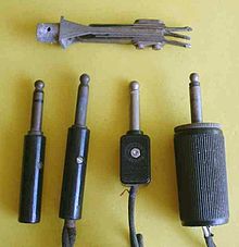
Old-style male tip-sleeve connectors. The leftmost plug has three conductors; the others have two. At the top is a three-conductor panel jack.

Modern profile 2-conductor male
1⁄4 in TS connectors
The original application for the 6.35 mm (1⁄4 in) phone jack was in manual telephone exchanges.[35] Many different configurations of these phone plugs were used, some accommodating five or more conductors, with several tip profiles. Of these many varieties, only the two-conductor version with a rounded tip profile was compatible between different manufacturers, and this was the design that was at first adopted for use with microphones, electric guitars, headphones, loudspeakers, and other audio equipment.
When a three-conductor version of the 6.35 mm plug was introduced for use with stereo headphones, it was given a sharper tip profile in order to make it possible to manufacture jacks that would accept only stereo plugs, to avoid short-circuiting the right channel of the amplifier. This attempt has long been abandoned, and now the convention is that all plugs fit all sockets of the same size, regardless of whether they are balanced or unbalanced, mono or stereo. Most 6.35 mm plugs, mono or stereo, now have the profile of the original stereo plug, although a few rounded mono plugs are still produced. The profiles of stereo miniature and sub-miniature plugs have always been identical to the mono plugs of the same size.
The results of this physical compatibility are:
- If a two-conductor plug is inserted into a three-conductor socket, the result is that the ring (right channel) of the socket is grounded. This property is deliberately used in several applications.[specify] However, if equipment is not designed for such a use, grounding the right channel causes a short circuit which has the potential to damage an audio amplifier channel. In any case, any signal from the right channel is naturally lost in this scenario.
- If a three-conductor plug is connected to a two-conductor socket, normally the result is to leave the ring of the plug unconnected. This open circuit is potentially dangerous to equipment utilizing vacuum tubes, but most solid-state devices will tolerate an open condition well. A three-conductor socket could be wired as an unbalanced mono socket to ground the ring in this situation, but the more conventional wiring is to leave the ring unconnected, exactly simulating a mono socket.
Because of a lack of standardization in the past regarding the dimensions (length) given to the ring conductor and the insulating portions on either side of it in 6.35 mm (1⁄4 in) phone connectors and the width of the conductors in different brands and generations of sockets, there are occasional issues with compatibility between differing brands of plug and socket. This can result in a contact in the socket bridging (shorting) the ring and sleeve contacts on a phone connector.
General use[edit]


A 3.5 mm 4-conductor TRRS phone connector

A 3.5 mm 5-conductor TRRRS phone connector
In the most common arrangement, consistent with the original intention of the design, the male plug is connected to a cable, and the female socket is mounted in a piece of equipment. A considerable variety of line plugs and panel sockets is available, including plugs suiting various cable sizes, right-angle plugs, and both plugs and sockets in a variety of price ranges and with current capacities up to 15 amperes for certain heavy-duty 1⁄4 in versions intended for loudspeaker connections.[36]
Common uses of phone plugs and their matching sockets include:
- Headphone and earphone jacks on a wide range of equipment. 6.35 mm (1⁄4 in) plugs are common on home and professional component equipment, while 3.5 mm plugs are nearly universal for portable audio equipment and headphones. 2.5 mm plugs are not as common, but are used on communication equipment such as cordless phones, mobile phones, and two-way radios, especially in the earliest years of the 21st century before the 3.5 mm became standard on mobile phones. The use of headphone jacks in smartphones is declining as of 2020 in favor of USB-C connectors and wireless Bluetooth solutions.
- Consumer electronics devices such as digital cameras, camcorders, and portable DVD players use 3.5 mm connectors for composite video and audio output. Typically, a TRS connection is used for mono unbalanced audio plus video, and a TRRS connection for stereo unbalanced audio plus video. Cables designed for this use are often terminated with RCA connectors on the other end. Sony also used this style of connection as the TV-Out on some models of Vaio laptop.
- Hands-free sets and headsets often use 3.5 mm or 2.5 mm connectors. TRS connectors are used for mono audio out and an unbalanced microphone (with a shared ground). Four-conductor TRRS phone connectors add an additional audio channel for stereo output. TRRS connectors used for this purpose are sometimes interoperable with TRS connectors, depending on how the contacts are used.[citation needed]
- Microphone inputs on tape and cassette recorders, sometimes with remote control switching on the ring, on early, monaural cassette recorders mostly a dual-pin version consisting of a 3.5 mm TS for the microphone and a 2.5 mm TS for remote control which switches the recorder’s power supply.
- Patching points (insert points) on a wide range of equipment.
Computer sound[edit]

3.5 mm jacks for microphone, audio out, and line-level audio in

A 3.5 mm plug for computer audio

A 3.5 mm headphone socket (TRS) on a computer
Personal computer sound cards, such as Creative Labs’ Sound Blaster line, use a 3.5 mm phone connector as a mono microphone input, and deliver a 5 V bias voltage on the ring to power the FET preamplifier built into electret microphones. Adjustments may be required to achieve compatibility between different manufacturers.[37]
The Apple PlainTalk microphone jack used on some older Macintosh systems is designed to accept an extended 3.5 mm three-conductor phone connector; in this case, the tip carries power for a preamplifier inside the microphone. It cannot accept a standard microphone without a preamp. If a PlainTalk-compatible microphone is not available, the jack can accept a line-level sound input.
Normally, 3.5 mm three-conductor sockets are used in computer sound cards for stereo output. Thus, for a sound card with 5.1 output, there will be three sockets to accommodate six channels: front left and right; surround left and right; and center and subwoofer. 6.1 and 7.1 channel sound cards from Creative Labs, however, use a single three-conductor socket (for the front speakers) and two four-conductor sockets.[b] This is to accommodate rear-center (6.1) or rear left and right (7.1) channels without the need for additional sockets on the sound card.
Some portable computers have a combined 3.5 mm TRS-TOSLINK jack, supporting stereo audio output using a TRS connector, or TOSLINK (stereo or 5.1 Dolby Digital/DTS) digital output using a suitable optical adapter. Most iMac computers have this digital/analog combo output feature as standard, with early MacBooks having two ports, one for analog/digital audio input and other for output. Support for input was dropped on various later models[38][39]
Some newer computers, such as Lenovo laptops, have 3.5 mm TRRS headset sockets, which are compatible with phone headsets and may be distinguished by a headset icon instead of the usual headphones or microphone icons. These are particularly used for voice over IP.
Video[edit]

Different length 3.5 mm TRRS connectors
Equipment requiring video with stereo audio input or output sometimes uses 3.5 mm TRRS connectors. Two incompatible variants exist, of 15 millimetres (0.59 in) and 17 mm (0.67 in) length, and using the wrong variant may either simply not work, or could cause physical damage.
Attempting to fully insert the longer (17 mm) plug into a receptacle designed for the shorter (15 mm) plug may damage the receptacle, and may damage any electronics located immediately behind the receptacle. However, partially inserting the plug will work as the tip/ring/ring distances are the same for both variants.
A shorter plug in a socket designed for the longer connector may not be retained firmly and may result in wrong signal routing or a short circuit inside the equipment (e.g. the plug tip may cause the contacts inside the receptacle – tip/ring 1, etc. — to short together).
The shorter 15 mm TRRS variant is more common and physically compatible with standard 3.5 mm TRS and TS connectors.
Recording equipment[edit]

Stereo devices which use «plug-in power»: the electret capsules are wired in this way.
Many small video cameras, laptops, recorders and other consumer devices use a 3.5 mm microphone connector for attaching a microphone to the system. These fall into three categories:[citation needed]
- Devices that use an unpowered microphone: usually a cheap dynamic or piezoelectric microphone. The microphone generates its own voltage and needs no power.
- Devices that use a self-powered microphone: usually a condenser microphone with an internal battery-powered amplifier.
- Devices that use a plug-in powered microphone: an electret microphone containing an internal FET amplifier. These provide a good quality signal, in a very small microphone. However, the internal FET needs a DC power supply, which is provided as a bias voltage for an internal preamp transistor. Plug-in power is supplied on the same line as the audio signal, using an RC filter. The DC bias voltage supplies the FET amplifier (at a low current), while the capacitor decouples the DC supply from the AC input to the recorder. Typically, V=1.5 V, R=1 kΩ, C=47 μF. If a recorder provides plug-in power, and the microphone does not need it, everything will usually work well. In the converse case (recorder provides no power; microphone needs power), no sound will be recorded.
PDAs and mobile phones[edit]

All iPhone models from the first generation to the 6S and SE (first generation) use a four-conductor (TRRS) phone connector (center) for a wired headset.
Three- or four-conductor (TRS or TRRS) 2.5 mm and 3.5 mm sockets are common on older cell phones and newer smartphones respectively, providing mono (three conductor) or stereo (four conductor) sound and a microphone input, together with signaling (e.g., push a button to answer a call). These are used both for handsfree headsets and for stereo headphones.
3.5 mm TRRS (stereo-plus-mic) sockets became particularly common on smartphones, and have been used e.g. by Nokia since 2006; they are often compatible with standard 3.5 mm stereo headphones. Some computers now also include a TRRS headset socket, compatible with the headsets intended for smartphones.
The four conductors of a TRRS connector are assigned to different purposes by different manufacturers. Any 3.5 mm plug can be plugged mechanically into any socket, but many combinations are electrically incompatible. For example, plugging TRRS headphones into a TRS headset socket, TRS headset into a TRRS socket, or plugging TRRS headphones from one manufacturer into a TRRS socket from another may not function correctly, or at all. Mono audio will usually work, but stereo audio or the microphone may not work.
TRRS standards[edit]
Two different forms are frequently found, both of which place left audio on the tip and right audio on the first ring (for compatibility with stereo connectors). Where they differ is in the placement of the microphone and return contacts.
The first, which places the ground return on the sleeve and the microphone on the second ring, is standardized in OMTP[40] and has been accepted as a national Chinese standard YDT 1885–2009. It is mostly used on older devices, such as older Nokia mobiles, older Samsung smartphones, and some Sony Ericsson phones,[41] and products meant for the Chinese market.[42][43] Headsets using this wiring may be indicated by black plastic separators between the rings.[44][43]
The second, which reverses these contacts, with the microphone on the sleeve, is used by Apple’s iPhone line until the 6S and SE (1st), and has become the de facto TRRS standard, to maintain compatibility with these products.[45][46][47] It is now used by HTC devices, recent Samsung, Nokia, and Sony phones, among others. This is referred to as CTIA/AHJ, and has the disadvantage that the mic will be shorted to ground if the body of the device is metal, and the sleeve has a flange that contacts it. Headsets using this wiring may be indicated by white plastic separators between the rings.[44][43]
If a CTIA headset is connected to a mobile phone with OMTP interface, the missing ground will effectively connect speakers in out-of-phase series, resulting in no voice on typical popular music recordings where the singers are in the center; in this case, if the main microphone button is held down, shorting across the microphone and restoring ground, the correct sound may be audible.[43]
| Standard | Tip | Ring 1 | Ring 2 | Sleeve | Devices using this standard |
|---|---|---|---|---|---|
| CTIA, AHJ | Left audio | Right audio | Ground | Microphone | Most Android devices.[48] Apple, HTC, LG, BlackBerry, latest Nokia (including 1st generation Lumia as well as later models[clarification needed]), latest Samsung, Jolla, Microsoft (including Surface, and Xbox One controller), Sony Playstation 4 (DualShock 4[49]), Google Pixel 4a |
| CTIA-style AV[50] | Left audio | Right audio | Ground | CVBS video | Apple iPod (up to 6th generation), Raspberry Pi (2014 onwards), Xbox 360 E, Zune (defunct), some older mobile phones (including Nokia N93, Nokia N95,[51] Samsung Galaxy S GT-I9000,[52] T-Mobile Sidekick 4G) |
| OMTP | Left audio | Right audio | Microphone | Ground | Old Nokia and also Lumia starting from the 2nd generation),[53] old Samsung (2012 Chromebooks), some old Sony Ericsson smartphones (2010 and 2011 Xperias),[54] Sony (PlayStation Vita), OnePlus One. |
| OMTP-style radios | Speaker | Clone | Microphone / PTT | Ground | Yaesu FT-60R amateur radio hand-held.[55][56][57] |
| Video/audio 1 | Left audio | CVBS video | Ground | Right audio | Sony and Panasonic camcorders. On some early Sony camcorders, this socket doubled up as a headphone socket. When a headphone plug was inserted, ring 2 was shorted to the sleeve contact and the camcorder output the right audio on ring 1.[58] |
| Video/audio 2 | CVBS video | Left audio | Right audio | Ground | Unknown camcorders, portable VCD and DVD players, Western Digital TV live!, some newer LG TVs. |
| Video/audio 3 | CVBS video | Left audio | Ground | Right audio | Toshiba TVs |
The 4-pole 3.5 mm connector is defined by the Japanese standard JEITA/EIAJ RC-5325A, «4-Pole miniature concentric plugs and jacks», originally published in 1993.[59] 3-pole 3.5 mm TRS connectors are defined in JIS C 6560. See also JIS C 5401 and IEC 60130-8.
Interoperability[edit]
The USB Type-C Cable and Connector Specification specifies a mapping from a USB-C jack to a 4-pole TRRS jack, for the use of headsets, and supports both CTIA and OMTP (YD/T 1885–2009) modes.[60] Some devices transparently handle many jack standards,[61][62] and there are hardware implementations of this available as components.[63] This is accomplished in some cases by applying a voltage to the sleeve and second ring to detect the wiring. The last two conductors may then be switches to allow a device made to one standard to be used with a headset made to the other.[64]
TRRRS standards[edit]
A TRRRS standard for 3.5 mm connectors was developed by ITU-T.[65] The standard, called P.382 (formerly P.MMIC), outlines technical requirements and test methods for a 5-conductor socket and plug configuration. Compared to the TRRS standard, TRRRS provides one extra conductor that can be used for connecting a second microphone or providing power to or from the audio accessory.
P.382 requires compliant sockets and plugs to be backward compatible with legacy TRRS and TRS connectors. Therefore, P.382-compliant TRRRS connectors should allow for seamless integration when used on new products. TRRRS connectors enable the following audio applications: active noise canceling, binaural recording and others, where dual analog microphone lines can be directly connected to a host device. It was commonly found on Sony phones starting with the Xperia Z1-XZ1 and Xperia 1 II.
Another TRRRS standard for 4.4 mm connectors following JEITA RC-8141C was introduced in 2015 and is used for balanced audio connections, in particular for headphone cables. This connector is often called a Pentaconn connector following the brand name of Nippon DICS (NDICS). It is used by some Sony products like the M1Z Walkman of their Signature series and by some Sennheiser products like the HD 820 headphone or the HDC 820 DAC headphone amplifier.[66][67]
Switch contacts[edit]

Miniature phone plugs and jacks. All are 3.5 mm except the gold-plated plug, which is 2.5 mm. One of the 3.5 mm jacks is two-conductor and the others are three conductor. In this collection the tan-colored jacks have normally-closed switches.
Panel-mounting jacks are often provided with switch contacts. Most commonly, a mono jack is provided with one normally closed (NC) contact, which is connected to the tip (live) connection when no plug is in the socket, and disconnected when a plug is inserted. Stereo sockets commonly provide two such NC contacts, one for the tip (left channel live) and one for the ring or collar (right channel live). Some designs of jack also have such a connection on the sleeve. As this contact is usually ground, it is not much use for signal switching, but could be used to indicate to electronic circuitry that the socket was in use.
Less commonly, some jacks are provided with normally open (NO) or change-over contacts, and/or the switch contacts may be isolated from the connector.
The original purpose of these contacts was for switching in telephone exchanges, for which there were many patterns. Two sets of change-over contacts, isolated from the connector contacts, were common. The more recent pattern of one NC contact for each signal path, internally attached to the connector contact, stems from their use as headphone jacks. In many amplifiers and equipment containing them, such as electronic organs, a headphone jack is provided that disconnects the loudspeakers when in use. This is done by means of these switch contacts. In other equipment, a dummy load is provided when the headphones are not connected. This is also easily provided by means of these NC contacts.
Other uses for these contacts have been found. One is to interrupt a signal path to enable other circuitry to be inserted. This is done by using one NC contact of a stereo jack to connect the tip and ring together when no plug is inserted. The tip is then made the output, and the ring the input (or vice versa), thus forming a patch point.
Another use is to provide alternative mono or stereo output facilities on some guitars and electronic organs. This is achieved by using two mono jacks, one for left channel and one for right, and wiring the NC contact on the right channel jack to the tip of the other, to connect the two connector tips together when the right channel output is not in use. This then mixes the signals so that the left channel jack doubles as a mono output.
Where a 3.5 mm or 2.5 mm jack is used as a DC power inlet connector, a switch contact may be used to disconnect an internal battery whenever an external power supply is connected, to prevent incorrect recharging of the battery.
A standard stereo jack is used on most battery-powered guitar effects pedals to eliminate the need for a separate power switch. In this configuration, the internal battery has its negative terminal wired to the sleeve contact of the jack. When the user plugs in a two-conductor (mono) guitar or microphone lead, the resulting short circuit between sleeve and ring connects an internal battery to the unit’s circuitry, ensuring that it powers up or down automatically whenever a signal lead is inserted or removed. A drawback of this design is the risk of inadvertently discharging the battery if the lead is not removed after use, such as if the equipment is left plugged in overnight.
Design[edit]

Examples of jack configurations, oriented so the plug ‘enters’ from the right. The most common circuit configurations are the simple mono and stereo jacks (A and B); however there are a great number of variants manufactured.[68]
- A two-conductor TS phone connector. The connection to the sleeve is the rectangle towards the right, and the connection to the tip is the line with the notch. Wiring connections are illustrated as white circles.
- A three-conductor TRS phone connector. The upper connector is the tip, as it is farther away from the sleeve. The sleeve is shown connected directly to the chassis, a very common configuration. This is the typical configuration for a balanced connection. Some jacks have metal mounting connections (which would make this connection) and some have plastic, to isolate the sleeve from the chassis, and provide a separate sleeve connection point, as in A.
- This three-conductor jack has two isolated SPDT switches. They are activated by a plug going into the jack, which disconnects one throw and connects the other. The white arrowheads indicate a mechanical connection, while the black arrowheads indicate an electrical connection. This would be useful for a device that turns on when a plug is inserted, and off otherwise, with the power routed through the switches.
- This three-conductor jack has two normally closed switches connected to the contacts themselves. This would be useful for a patch point, for instance, or for allowing another signal to feed the line until a plug is inserted. The switches open when a plug is inserted. A common use for this style of connector is a stereo headphone jack that shuts off the default output (speakers) when the connector is plugged in.

- Sleeve: usually ground
- Ring: Right-hand channel for stereo signals, negative polarity for balanced mono signals, power supply for power-using mono signal sources
- Tip: Left-hand channel for stereo signals, positive polarity for balanced mono signals, signal line for unbalanced mono signals
- Insulating rings
The connector assembly is usually made by few hollow and one solid pins. The jack is then assembled together by using an electric insulator material (such as plastics e.g. POM) into a single piece in such a way that pins don’t short circuit.
| Pin | Unbalanced mono | Balanced mono in/out[69] (simplex) | Unbalanced stereo | |
|---|---|---|---|---|
| In/out (simplex) | Insert[70] | |||
| Tip | Signal | Send or return signal | Positive, hot | Left channel |
| Ring | Ground, or no connection | Return or send signal | Negative, cold | Right channel |
| Sleeve | Ground |
- Notes
-
- The first version of the popular Mackie 1604 mixer, the CR1604, used a tip negative, ring positive jack wiring scheme on the main left and right outputs.[71][72]
- Early QSC amplifiers used a tip negative, ring positive input wiring scheme.[73]
- Whirlwind Line Balancer/Splitters do not use the sleeve as a conductor on their unbalanced 6.35 mm/1⁄4 in TRS phone input. Tip and ring are wired to the transformer’s two terminals; the sleeve is not connected.[74]
Balanced audio[edit]
When a phone connector is used to make a balanced connection, the two active conductors are both used for a monaural signal. The ring, used for the right channel in stereo systems, is used instead for the inverting input. This is a common use in small audio mixing desks, where space is a premium and they offer a more compact alternative to XLR connectors. Another advantage offered by TRS phone connectors used for balanced microphone inputs is that a standard unbalanced signal lead using a TS phone jack can simply be plugged into such an input. The ring (right channel) contact then makes contact with the plug body, correctly grounding the inverting input.

A disadvantage of using phone connectors for balanced audio connections is that the ground mates last and the socket grounds the plug tip and ring when inserting or disconnecting the plug. This causes bursts of hum, cracks and pops and may stress some outputs as they will be short circuited briefly, or longer if the plug is left half in.
This problem does not occur when using the ‘gauge B’ (BPO) phone connector (PO 316)[75] which although it is of 0.25 in (6.35 mm) diameter has a smaller tip and a recessed ring so that the ground contact of the socket never touches the tip or ring of the plug. This type was designed for balanced audio use, being the original telephone ‘switchboard’ connector and is still common in broadcast, telecommunications and many professional audio applications where it is vital that permanent circuits being monitored (bridged) are not interrupted by the insertion or removal of connectors. This same tapered shape used in the ‘gauge B’ (BPO) plug can be seen also in aviation and military applications on various diameters of jack connector including the PJ-068 and ‘bantam’ plugs. The more common straight-sided profile used in domestic and commercial applications and discussed in most of this article is known as ‘gauge A’.
XLR connectors used in much professional audio equipment mate the ground signal on pin 1 first.
Unbalanced audio[edit]
Phone connectors with three conductors are also commonly used as unbalanced audio patch points (or insert points, or simply inserts), with the output on many mixers found on the tip (left channel) and the input on the ring (right channel). This is often expressed as «tip send, ring return». Other mixers have unbalanced insert points with «ring send, tip return». One advantage of this system is that the switch contact within the panel socket, originally designed for other purposes, can be used to close the circuit when the patch point is not in use. An advantage of the tip send patch point is that if it is used as an output only, a 2-conductor mono phone plug correctly grounds the input. In the same fashion, use of a «tip return» insert style allows a mono phone plug to bring an unbalanced signal directly into the circuit, though in this case the output must be robust enough to withstand being grounded. Combining send and return functions via single 1⁄4 in TRS connectors in this way is seen in very many professional and semi-professional audio mixing desks, because it halves the space needed for insert jack fields which would otherwise need two jacks, one for send and one for return. The tradeoff is that unbalanced signals are more prone to buzz, hum and outside interference.
In some three-conductor TRS phone inserts, the concept is extended by using specially designed phone jacks that will accept a mono phone plug partly inserted to the first click and will then connect the tip to the signal path without breaking it. Most standard phone connectors can also be used in this way with varying success, but neither the switch contact nor the tip contact can be relied upon unless the internal contacts have been designed with extra strength for holding the plug tip in place. Even with stronger contacts, an accidental mechanical movement of the inserted plug can interrupt signal within the circuit. For maximum reliability, any usage involving first click or half-click positions will instead rewire the plug to short tip and ring together and then insert this modified plug all the way into the jack.
The TRS tip return, ring send unbalanced insert configuration is mostly found on older mixers. This allowed for the insert jack to serve as a standard-wired mono line input that would bypass the mic preamp. However tip send has become the generally accepted standard for mixer inserts since the early-to-mid 1990s. The TRS ring send configuration is still found on some compressor sidechain input jacks such as the dbx 166XL.[76]
In some very compact equipment, 3.5 mm TRS phone connectors are used as patch points.
Some sound recording devices use a three-conductor phone connector as a mono microphone input, using the tip as the signal path and the ring to connect a standby switch on the microphone.
Poor connections[edit]
Connectors that are tarnished, or that were not manufactured within tight tolerances, are prone to cause poor connections.[77] Depending upon the surface material of the connectors, tarnished ones can be cleaned with a burnishing agent (for solid brass contacts typical) or contact cleaner (for plated contacts).[77]
See also[edit]
- Banana connector
- Coaxial power connector
Explanatory notes[edit]
- ^ 0.210 inch inside diameter jacks are also found in discontinued Bell & Howell 16 mm projector speakers.[32]
- ^ Creative’s documentation uses the word pole instead of conductor to describe connector contacts.
References[edit]
- ^ International Library of Technology: … Principles of Telephony … International Textbook Company, Scranton, PA. 1907. p. 36.
tip ring sleeve 0-1922.
- ^ Robert McLeish (2005). Radio Production. Newnes. ISBN 0-240-51972-8.
- ^ Standard Reference Designations for Electrical and Electronics Parts and Equipments: IEEE 200-1975 (Reaffirmed 1988): Section 4.1.5.3. IEEE and ANSI, New York, NY. 1975.
- ^ Reference Designations for Electrical and Electronics Parts and Equipment: ASME Y14.44-2008 (Replaced IEEE 200-1975): Section 2.1.5.3. ASME, Fairfield, NJ. 2008. Archived from the original on 2010-03-13.
- ^ Gary D. Davis and Ralph Jones (1989). The Sound Reinforcement Handbook. Hal Leonard. ISBN 0-88188-900-8.
- ^
- «Barrel – Audio Connectors». Digi-Key catalog.
- «Audio-Video Connectors». Mouser Electronics catalog.
- «Jacks & Plugs». Switchcraft catalog.
- «Definition of: mini-phone connector». PC Magazine Encyclopedia.
Also called a 3.5 mm or 1/8″ connector, it is a plug and socket widely used for analog audio signals in portable devices.
- «Mini Phone Plug Adapters». RAM Electronics online catalog.
(e.g.) 3.5mm female stereo mini phone jack to 1/4″ male Stereo phone plug Adapter
- ^
- Lewallen, Dale (1993). This Old PC. Ziff-Davis Press. p. 362. ISBN 978-1-56276-108-0. Retrieved September 8, 2016.
Remember that sound cards use the smaller 1/8-inch mini-phono plug…
- «Connect your Mac to a home stereo, iPod, iPad, musical instruments, or speakers». Apple.com. Apple Inc. Retrieved September 8, 2016.
1/8-inch stereo mini-phono plug adapter.
- «Glossary». Monoprice. Retrieved September 8, 2016.
3.5 mm Plug/Jack: Also referred to as a 1/8 inch, auxiliary input, mini stereo, and mini phono.
- «Beckman Coulter Automatic Temperature Compensation (ATC) Probe» (PDF). Beckman Coulter. 2008. p. 1. Archived from the original (PDF) on September 16, 2016. Retrieved September 8, 2016.
The 3.5mm mini-phono plug connector of the ATC Probe plugs into the 3.5mm mini-phono jack on the pH meter.
- Divine, John (September 7, 2016). «Apple’s iPhone 7 and its 10 Flashy Features Won’t Move AAPL Stock». USNews.com. U.S. News & World Report. Retrieved September 8, 2016.
…instead of the headphone jack…. There will be a lightning-to-mini phono adapter included as well.
- Lewallen, Dale (1993). This Old PC. Ziff-Davis Press. p. 362. ISBN 978-1-56276-108-0. Retrieved September 8, 2016.
- ^ a b «The Birthplace of the Telephone | Thomas Sherwin Chapter #14». www.newvision-sherwinpioneers.org.
- ^ Frank Lewis Dyer. Edison: His Life And Inventions, p. 71.
- ^ «When Phone Operators Were Unruly Teenage Boys». The Atlantic. 19 September 2014. Retrieved 2017-10-25.
- ^ «Chapter 3 Local Manual Systems» (PDF).
- ^ «First Commercial Telephone Exchange – Today in History: January 28». 28 January 2020.
- ^ «A History of the Telephone». www.scaruffi.com.
- ^ a b «Patent Public Search | USPTO». ppubs.uspto.gov.
- ^ Chapuis, Robert J. (2003). 100 Years of Telephone Switching. Amsterdam, The Netherlands: IOS Press. p. 51. ISBN 9784274906114.
- ^ «U.S. Patent 305,021, September 1884».
- ^ Scribner, C. E. «U.S. Patent 489,570: Spring Jack Switch».
- ^ «Telephone switchboard-plug».
- ^ «Western Electric Telephonic Apparatus and Supplies (1907)».
- ^ «MIL-DTL-642/5B». 3 March 2021.
- ^ «MIL-DTL-642F: Plugs, Telephone, and Accessory Screws» (PDF).
- ^ «All-right jack: Simple but effective plug-in has endured for more than a century». Retrieved 2016-09-11.
- ^ «Sony history 1960s». Sony official website.
- ^ Description of 3.5 mm earphone jack in described model: «Vintage Sony 1960’S EFM-117J Radio». WorthPoint. Retrieved 2016-01-25.
- ^ 3.5 mm Stereo Plug, CUI Devices, retrieved 2021-09-01
- ^ «3.5 mm Headset: Accessory Specification». Android Open Source Project. Retrieved 2019-06-15.
- ^ «Build a Data Cable for the Yaesu VX-6». ad7gd.net.
- ^ «Geek Out V2+ User Manual».
- ^ Chinn, Howard (July 1947). «Single Jacks for Broadcast Application» (PDF). Audio Engineering. 31 (6).
- ^ a b «The Low-down On Analogue Interfacing -«. www.soundonsound.com. Retrieved 16 August 2018.
- ^ Gibson, Bill. (2007) The Ultimate Live Sound Operator’s Handbook, p. 202. Hal Leonard Corporation. ISBN 1-4234-1971-5
- ^ «Switchcraft Telephone Jack and Telephone Plug Mating Chart» (PDF). Archived from the original (PDF) on 2014-04-13. Retrieved 2013-06-24.
- ^ «PL-55». Radionerds.com. Retrieved 17 August 2018.
- ^ «Item # TP-120, Telephone Plug». Amphenol Nexus Technologies, Inc. Retrieved 2012-01-12.
- ^ Ranjan Parekh; Ranjan (2006). Principles of Multimedia. Tata McGraw-Hill Education. pp. 225–. ISBN 978-0-07-058833-2.
- ^ «Switchcraft Z15J 1/4″ High Power Speaker Jack». Full Compass. Retrieved October 24, 2011.
High power 2-conductor speaker jack carries 15A (continuous) audio speaker current levels.
- ^ «Computer microphones». Retrieved 2021-12-11.
- ^ «Questions Answered 4: Optical Output on the Mac«.[permanent dead link]
- ^ «Which one is the microphone jack?». MacRumors Forums.
- ^ «Wired Analogue Audio» (PDF). Retrieved 2012-06-01.
- ^ «MEElectronics – P version headset earphone compatibility». Meelec.com. Archived from the original on 2010-12-27. Retrieved 2013-07-14.
- ^ «iphone — Why do Chinese EarPods not work with German MacBook Pro?». Ask Different. Retrieved 2020-04-24.
- ^ a b c d «Linx:What is your mobile phone headset jack standard: OMTP or CTIA?-Headset OEM|Earphone Factory|Headphone Supplier —China LINX CO,.LTD». www.headphonefactory.net. Retrieved 2020-04-24.
In order to fit the Chinese national conditions, Apple China released Earpods with some changes, specifically for the Chinese market, to make it in line with the Chinese domestic OMTP standard. … Therefore, iPhone original headsets sod in China are different from Earpods sold in other regions.
- ^ a b «IPhone国行耳机不兼容问题 — Apple 社区». discussionschinese.apple.com. Retrieved 2020-04-24.
- ^ «Headphone inline controls – how they differ on Apple iOS vs. Android/Nokia | Hacker News». news.ycombinator.com. Retrieved 2020-04-24.
- ^ «Xiaomi In-Ear Headphones Pro HD (2 +1 Hybrid)». Headphone Reviews and Discussion — Head-Fi.org. Retrieved 2020-04-24.
- ^ «Smartphone Headset Standards: Apple iPhone, AHJ (CTIA), & OMTP». Headset Buddy Help. Retrieved 2020-04-24.
- ^ «3.5 mm Headset Jack: Device Specification». Android Open Source Project.
- ^ «Smartphone Headset Standards: Apple iPhone, AHJ (CTIA), & OMTP». Retrieved 15 August 2021.
- ^ www.cablechick.com.au. «Understanding TRRS and Audio Jacks – Cable Chick Blog». www.cablechick.com.au. Retrieved 16 August 2018.
- ^ «TV Out on the Nokia N95». All About Symbian. Retrieved 6 October 2019.
- ^ «Singtel Group, first in the world to launch breakthrough Android 2.1 Samsung Galaxy S». singtel.com. Retrieved 6 October 2019.
- ^ «Jays AB headset for Windows Phone and a note on headset standards». Allaboutwindowsphone.com. Retrieved 26 March 2017.
- ^ «2012 Xperia range uses different 3.5mm headset standard | Xperia Blog». www.xperiablog.net. 27 February 2012. Retrieved 2017-08-17.
- ^ Yaesu FT-60R Technical Supplement (PDF). VERTEX STANDARD CO., LTD. 2005. pp. 10, 13.
- ^ «Radio Wiring — ArgentWiki». wiki.argentdata.com. Retrieved 2020-05-29.
- ^ «MH-37A4B wiring diagram». www.qsl.net. Retrieved 2020-05-29.
- ^ Sony and Panasonic camcorder service manuals
- ^ «RC-5325A». www.jeita.or.jp.
- ^ «USB Type-C Cable and Connector Specification Release 2.1». See Audio Adapter Accessory Mode (Appendix A)
- ^ FAQ – What type of wired headsets can I use with my Nokia Lumia phone? – «Nokia Lumia 820 and 920 support both American Headset Jack (AHJ) headsets and standard Nokia OMTP headsets.»
- ^ Jays AB headset for Windows Phone and a note on headset standards – «Nokia’s Windows Phone 8 devices (Nokia Lumia 520, 521, 620, 720, 810, 820, 822, 920, 925, and 928) use a new universal connector, enabling the use of both AHJ and OMTP headsets.»
- ^ «TS3A227E Autonomous Audio Accessory Detection and Configuration Switch».
- ^ Digital Silence (earphone manufacturer): explanation of TRRS connectors and availability of adapter.
- ^ «ITU-T Work Programme». Retrieved 26 March 2017.
- ^ Sauerborn, Denis (2019-04-12). «Pentaconn – Das steckt hinter der 4,4 Millimeter-Kopfhörerverbindung» [Pentaconn — About the 4.4 millimeter headphone connector]. mobile fidelty magazine (in German). Archived from the original on 2022-05-25. Retrieved 2022-11-28.
- ^ «About Us». Pentaconn Global. Subang Jaya, Selangor, Malaysia: Nippon DICS SDN BHD. 2016. Archived from the original on 2022-11-11. Retrieved 2022-11-28.
- ^ «Jack Schematics table» (PDF).
- ^ «Frequently Asked Questions». Retrieved 2012-05-28.
- ^ «Diagrams» (PDF). Retrieved 2012-05-28.
- ^ Sweetwater (2000-01-13). «Sweetwater inSync». Sweetwater.com. Retrieved 2013-07-14.
- ^ «Silent Way’s recording tricks- Mackie CR-1604 mixer». Silentway.com. Retrieved 2013-07-14.
- ^ «QSC Audio Products. Frequently Asked Questions«.
- ^ [1] Archived November 10, 2006, at the Wayback Machine
- ^ «Neutrik mil-b-gauge-type plugs«.
- ^ «dbx 166XL compressor with balanced TRS tip send input and output jacks and one TRS ring send sidechain jack».
- ^ a b «Q. What’s wrong with my patchbay? -«. www.soundonsound.com.
External links[edit]
- The 19th Century plug that’s still being used—BBC News
- «The Rise and Fall of the Headphone Jack». CNBC. 2019-08-28. Archived from the original on 2021-11-04.
«Pentaconn» redirects here. For the camera manufacturer, see Pentacon.
The three parts: tip, ring and sleeve
A pair of phone connectors: A plug (right) is inserted in a socket (jack, left). Note the flat open contact spring parallel to and inside the tip contact spring. When the plug is removed, those contacts close to connect a circuit; such a connection is said to be «normal». Inserting the plug connects its tip to one part of that circuit instead.
A phone connector, also known as phone jack, audio jack, headphone jack or jack plug, is a family of electrical connectors typically used for analog audio signals. A plug, the male connector, is inserted into the jack, the female connector.
The phone connector was invented for use in telephone switchboards in the 19th century and is still widely used.
The phone connector is cylindrical in shape, with a grooved tip to retain it. In its original audio configuration, it typically has two, three, four or, occasionally, five contacts. Three-contact versions are known as TRS connectors (tip, ring, sleeve). Ring contacts are typically the same diameter as the sleeve, the long shank. Similarly, two-, four- and five-contact versions are called TS, TRRS and TRRRS connectors respectively. The outside diameter of the «sleeve» conductor is 6.35 millimetres (1⁄4 inch). The «mini» connector has a diameter of 3.5 mm (0.14 in) and the «sub-mini» connector has a diameter of 2.5 mm (0.098 in). The «mini» connector has a length of 14 millimetres (0.55 in).
Other terms[edit]
Specific models, and connectors used in specific applications, may be termed e.g. stereo plug, headphone jack, microphone jack, aux input, etc. The 3.5 mm versions are mini-phone, mini-stereo, mini jack, etc.[1][failed verification]
In the UK, jack plug and jack socket are the male and female phone connectors.[2] In the US, a stationary (more fixed) electrical connector is the jack.[3][4] The terms phone plug and phone jack sometimes refer to different genders of phone connectors,[5] but also sometimes refer to the RJ11 and older telephone plugs and corresponding jacks that connect wired telephones to wall outlets.
Phone plugs and jacks are different from phono plugs and phono jacks (or in the UK, phono socket) which are RCA connectors common in consumer hi-fi and audiovisual equipment. The 3.5 mm connector is, however, sometimes—but counter to the connector manufacturers’ nomenclature[6]—referred to as mini phono.[7]
Historical development[edit]
Phone connectors:
- 2.5 mm (1⁄10 in) mono (TS)
- 3.5 mm (1⁄8 in) mono (TS)
- 3.5 mm (1⁄8 in) stereo (TRS)
- 6.35 mm (1⁄4 in) stereo (TRS)
Quarter-inch size[edit]
Modern phone connectors are available in three standard sizes. The original 1⁄4 inch (6.35 mm) version descends from as early as 1877, when the first-ever telephone switchboard was installed at 109 Court Street in Boston in a building owned by Charles Williams, Jr.;[8][9] or 1878, when an early switchboard was used for the first commercial manual telephone exchange[10][11] in New Haven, Connecticut created by George W. Coy.[12][13] The 1877 switchboard was last known to be located in the lobby of 185 Franklin Street, Boston.[8]
In February 1884, C. E. Scribner was issued US Patent 293,198[14] for a «jack-knife» connector that is the origin of calling the receptacle a «jack».[15] Scribner was issued U.S. Patents 262,701,[14] 305,021,[16] and 489,570 relating to an improved design that more closely resembles the modern plug.[17] The current form of the switchboard-plug was patented prior to 1902, when Henry P. Clausen received a patent on an improved design.[18] It is today still used on mainstream musical equipment, especially on electric guitars.
Western Electric was the manufacturing arm of the Bell System, and thus originated or refined most of the engineering designs, including the telephone jacks and plugs which were later adopted by other industries, including the U.S. military.
By 1907, Western Electric had designed a number of models for different purposes, including:[19]
- Code No. 47 2-conductor plugs for use with type 3, 91, 99, 102, 103, 108, and 124 jacks—used for switchboards
- Code No. 85 3-conductor plugs for use with type 77 jacks—used for the operator’s head telephone
- Code No. 103 twin 2-conductor plugs for use with type 91, and type 99 jacks—used for the operator’s head telephone and chest transmitter (microphone)
- Code No. 109 3-conductor plugs for use with jack 92 on telephone switchboards (with the same basic shape as the modern Bantam plugs)
- Code No. 110, 3-conductor plug for use with jacks 49, 117, 118, 140, and 141 on switchboards
- Code No. 112, twin 2-conductor plug for use with jacks 91 and 99—used for the operator’s head telephone and chest, with a transmitter cutout key (microphone mute)
- Code No. 116, 1-conductor plug for use with cordless jack boxes
- Code No. 126, 3-conductor plug for use with type 132 and type 309 jacks on portable street railway sets
By 1950, the two main plug designs were:
- WE-309 (compatible with 3⁄16-inch jacks, such as 246 jack), for use on high-density jack panels such as the 608A
- WE-310 (compatible with 1⁄4-inch jacks, such as the 242)
Several modern designs have descended from those earlier versions:
- B-Gauge standard BPO316 (not compatible with EIA RS-453)
- EIA RS-453: Dimensional, Mechanical and Electrical Characteristics Defining Phone Plugs & Jacks standard of 0.206 in (5.2 mm) diameter, also found in IEC 60603-11:1992 Connectors for frequencies below 3 MHz for use with printed boards – Part 11: Detail specification for concentric connectors (dimensions for free connectors and fixed connectors).
Military variants[edit]
U.S. military versions of the Western Electric plugs were initially specified in Amendment No.1, MIL-P-642, and included:
- M642/1-1
- M642/1-2
- M642/2-1
- M642/2-2
- M642/4-1
- M642/4-2
- MIL-P-642/2, also known as PJ-051. (Similar to Western Electric WE-310, and thus not compatible with EIA RS-453)
- MIL-P-642/5A: Plug, Telephone (TYPE PJ-068) and Accessory Screws (1973),[20] and MIL-DTL-642F: Plugs, Telephone, and Accessory Screws (2015),[21] with 0.206 in (5.2 mm) diameter, also known by the earlier Signal Corps PL-68 designation. These are commonly used as the microphone jack for aviation radios, and on Collins S-line and many Drake amateur radios. MIL-DTL-642F states, «This specification covers telephone plugs used in telephone (including telephone switchboard consoles), telegraph, and teletype circuits, and for connecting headsets, handsets, and microphones into communications circuits.»
Miniature size[edit]
The 3.5 mm or miniature size was originally designed in the 1950s as two-conductor connectors for earpieces on transistor radios, and remains a standard still used today.[22] This roughly half-sized version of the original, popularized by the Sony EFM-117J radio (released in 1964),[23][24][failed verification] is still commonly used in portable applications. The three-conductor version became very popular with its application on the Walkman in 1979, as unlike earlier transistor radios, these devices had no speaker of their own; the usual way to listen to them was to plug in headphones. There is also an EIA standard for 0.141-inch miniature phone jacks.
The 2.5 mm or sub-miniature sizes were similarly popularized on small portable electronics. They often appeared next to a 3.5 mm microphone jack for a remote control on-off switch on early portable tape recorders; the microphone provided with such machines had the on-off switch and used a two-pronged connector with both the 3.5 and 2.5 mm plugs. They were also used for low-voltage DC power input from wall adapters. In the latter role they were soon replaced by coaxial DC power connectors. 2.5 mm phone jacks have also been used as the headset jacks on mobile telephones (see § PDAs and mobile phones).
The 3.5 mm and 2.5 mm sizes are sometimes called 1⁄8 in and 3⁄32 in respectively in the United States, though those dimensions are only approximations.[25] All sizes are now readily available in two-conductor (unbalanced mono) and three-conductor (balanced mono or unbalanced stereo) versions.
Four-conductor versions of the 3.5 mm plug and jack are used for certain applications. A four-conductor version is often used in compact camcorders and portable media players, providing stereo sound and composite analog video. It is also used for a combination of stereo audio, a microphone, and controlling media playback, calls, volume and/or a virtual assistant on some laptop computers and most mobile phones,[26] and some handheld amateur radio transceivers from Yaesu.[27] Some headphone amplifiers have used it to connect «balanced» stereo headphones, which require two conductors per audio channel as the channels do not share a common ground.[28]
Broadcast usage[edit]
By the 1940s, broadcast radio stations were using Western Electric Code No. 103 plugs and matching jacks for patching audio throughout studios. This connector was used because of its use in AT&T’s Long Line circuits for distribution of audio programs over the radio networks’ leased telephone lines.[citation needed] Because of the large amount of space these patch panels required, the industry began switching to 3-conductor plugs and jacks in the late 1940s, using the WE Type 291 plug with WE type 239 jacks. The type 291 plug was used instead of the standard type 110 switchboard plug because the location of the large bulb shape on this TRS plug would have resulted in both audio signal connections being shorted together for a brief moment while the plug is being inserted and removed. The Type 291 plug avoids this by having a shorter tip.[29][page needed]
Patch bay connectors[edit]
Professional audio and the telecommunication industry use a 0.173 in (4.4 mm) diameter plug, associated with trademarked names including Bantam, TT, Tini-Telephone, and Tini-Tel. They are not compatible with standard EIA RS-453/IEC 60603-11 1/4-inch jacks. In addition to a slightly smaller diameter, they have a slightly different geometry.[30] The three-conductor TRS versions are capable of handling balanced line signals and are used in professional audio installations. Though unable to handle as much power, and less reliable than a 6.35 mm (0.250 in) jack,[31] Bantam connectors are used for professional console and outboard patchbays in recording studio and live sound applications, where large numbers of patch points are needed in a limited space.[30] The slightly different shape of Bantam plugs is also less likely to cause shorting as they are plugged in.[citation needed]
Less common[edit]
A dual 310 patch cable, two-pin phone plug
A two-pin version, known to the telecom industry as a «310 connector», consists of two 1⁄4-inch phone plugs at a centre spacing of 5⁄8 inch (16 mm). The socket versions of these can be used with normal phone plugs provided the plug bodies are not too large, but the plug version will only mate with two sockets at 5⁄8 inches centre spacing, or with line sockets, again with sufficiently small bodies. These connectors are still used today in telephone company central offices on «DSX» patch panels for DS1 circuits. A similar type of 3.5 mm connector is often used in the armrests of older aircraft, as part of the on-board in-flight entertainment system. Plugging a stereo plug into one of the two mono jacks typically results in the audio coming into only one ear. Adapters are available.
A short-barrelled version of the phone plug was used for 20th century high-impedance mono headphones, and in particular those used in World War II aircraft. These have become rare. It is physically possible to use a normal plug in a short socket, but a short plug will neither lock into a normal socket nor complete the tip circuit.
Less commonly used sizes, both diameters and lengths, are also available from some manufacturers, and are used when it is desired to restrict the availability of matching connectors, such as 0.210-inch (5.3 mm) inside diameter jacks for fire safety communication in public buildings.[a]
Aviation and US military connectors[edit]
US military phone connectors include both 0.25-in. (6.35 mm) and 0.21-in. (5.34 mm) diameter plugs, which both mate with the M641-series open frame jacks, exemplified by Switchcraft C11 and C12 series jacks. Military specifications and standards relating to phone connectors include MIL-STD 202, MIL-P-642/*, and MIL-J-641.
Commercial and general aviation (GA) civil airplane headset plugs are similar, but not identical. A standard 1⁄4-in. monaural plug, type PL-55[33] (both two-conductor phone plugs, also called PJ-055B, which mate with JK-24 and JK-34A jacks) is used for headphones. On many newer GA aircraft the headphone jack is a standard 1⁄4-in. phone connector wired in the standard unbalanced stereo configuration instead of the PJ-055 to allow stereo music sources to be reproduced.
Aviation headphones are paired with special tip-ring-sleeve, 3/16-in (0.206 in)/5.23-mm diameter plug,[citation needed] type PJ-068 (PL-68), for the microphone. The PJ-068 mates with a JK-33 jack (Switchcraft C-12B), and is similar to the Western Electric plug WE-109. In the microphone plug the Ring is used for the microphone hot and the sleeve is ground. The extra (tip) connection in the microphone plug is often left unconnected but is also sometimes used for various functions, most commonly an optional push-to-talk switch, but on some aircraft, it carries headphone audio and on others a DC supply.[citation needed]
Aviation plug type U-174/U or Nexus TP120, commonly used on military aircraft and civil helicopters
Military aircraft and civil helicopters have another type termed a U-174/U; These are also known as NATO plugs or Nexus TP120[34] phone plugs. They are similar to 1⁄4-in. (6.35 mm) plug, but with a 7.10 mm (0.280 in) diameter short shaft with an extra ring, i.e. four conductors in total, allowing two for the headphones (mono), and two for the microphone. There is a confusingly similar four conductor British connector with a slightly smaller diameter and a different wiring configuration used for headsets in many UK Military aircraft and often also referred to as a NATO or UK NATO connector.
Mono and stereo compatibility[edit]
Old-style male tip-sleeve connectors. The leftmost plug has three conductors; the others have two. At the top is a three-conductor panel jack.
Modern profile 2-conductor male
1⁄4 in TS connectors
The original application for the 6.35 mm (1⁄4 in) phone jack was in manual telephone exchanges.[35] Many different configurations of these phone plugs were used, some accommodating five or more conductors, with several tip profiles. Of these many varieties, only the two-conductor version with a rounded tip profile was compatible between different manufacturers, and this was the design that was at first adopted for use with microphones, electric guitars, headphones, loudspeakers, and other audio equipment.
When a three-conductor version of the 6.35 mm plug was introduced for use with stereo headphones, it was given a sharper tip profile in order to make it possible to manufacture jacks that would accept only stereo plugs, to avoid short-circuiting the right channel of the amplifier. This attempt has long been abandoned, and now the convention is that all plugs fit all sockets of the same size, regardless of whether they are balanced or unbalanced, mono or stereo. Most 6.35 mm plugs, mono or stereo, now have the profile of the original stereo plug, although a few rounded mono plugs are still produced. The profiles of stereo miniature and sub-miniature plugs have always been identical to the mono plugs of the same size.
The results of this physical compatibility are:
- If a two-conductor plug is inserted into a three-conductor socket, the result is that the ring (right channel) of the socket is grounded. This property is deliberately used in several applications.[specify] However, if equipment is not designed for such a use, grounding the right channel causes a short circuit which has the potential to damage an audio amplifier channel. In any case, any signal from the right channel is naturally lost in this scenario.
- If a three-conductor plug is connected to a two-conductor socket, normally the result is to leave the ring of the plug unconnected. This open circuit is potentially dangerous to equipment utilizing vacuum tubes, but most solid-state devices will tolerate an open condition well. A three-conductor socket could be wired as an unbalanced mono socket to ground the ring in this situation, but the more conventional wiring is to leave the ring unconnected, exactly simulating a mono socket.
Because of a lack of standardization in the past regarding the dimensions (length) given to the ring conductor and the insulating portions on either side of it in 6.35 mm (1⁄4 in) phone connectors and the width of the conductors in different brands and generations of sockets, there are occasional issues with compatibility between differing brands of plug and socket. This can result in a contact in the socket bridging (shorting) the ring and sleeve contacts on a phone connector.
General use[edit]
A 3.5 mm 4-conductor TRRS phone connector
A 3.5 mm 5-conductor TRRRS phone connector
In the most common arrangement, consistent with the original intention of the design, the male plug is connected to a cable, and the female socket is mounted in a piece of equipment. A considerable variety of line plugs and panel sockets is available, including plugs suiting various cable sizes, right-angle plugs, and both plugs and sockets in a variety of price ranges and with current capacities up to 15 amperes for certain heavy-duty 1⁄4 in versions intended for loudspeaker connections.[36]
Common uses of phone plugs and their matching sockets include:
- Headphone and earphone jacks on a wide range of equipment. 6.35 mm (1⁄4 in) plugs are common on home and professional component equipment, while 3.5 mm plugs are nearly universal for portable audio equipment and headphones. 2.5 mm plugs are not as common, but are used on communication equipment such as cordless phones, mobile phones, and two-way radios, especially in the earliest years of the 21st century before the 3.5 mm became standard on mobile phones. The use of headphone jacks in smartphones is declining as of 2020 in favor of USB-C connectors and wireless Bluetooth solutions.
- Consumer electronics devices such as digital cameras, camcorders, and portable DVD players use 3.5 mm connectors for composite video and audio output. Typically, a TRS connection is used for mono unbalanced audio plus video, and a TRRS connection for stereo unbalanced audio plus video. Cables designed for this use are often terminated with RCA connectors on the other end. Sony also used this style of connection as the TV-Out on some models of Vaio laptop.
- Hands-free sets and headsets often use 3.5 mm or 2.5 mm connectors. TRS connectors are used for mono audio out and an unbalanced microphone (with a shared ground). Four-conductor TRRS phone connectors add an additional audio channel for stereo output. TRRS connectors used for this purpose are sometimes interoperable with TRS connectors, depending on how the contacts are used.[citation needed]
- Microphone inputs on tape and cassette recorders, sometimes with remote control switching on the ring, on early, monaural cassette recorders mostly a dual-pin version consisting of a 3.5 mm TS for the microphone and a 2.5 mm TS for remote control which switches the recorder’s power supply.
- Patching points (insert points) on a wide range of equipment.
Computer sound[edit]
3.5 mm jacks for microphone, audio out, and line-level audio in
A 3.5 mm plug for computer audio
A 3.5 mm headphone socket (TRS) on a computer
Personal computer sound cards, such as Creative Labs’ Sound Blaster line, use a 3.5 mm phone connector as a mono microphone input, and deliver a 5 V bias voltage on the ring to power the FET preamplifier built into electret microphones. Adjustments may be required to achieve compatibility between different manufacturers.[37]
The Apple PlainTalk microphone jack used on some older Macintosh systems is designed to accept an extended 3.5 mm three-conductor phone connector; in this case, the tip carries power for a preamplifier inside the microphone. It cannot accept a standard microphone without a preamp. If a PlainTalk-compatible microphone is not available, the jack can accept a line-level sound input.
Normally, 3.5 mm three-conductor sockets are used in computer sound cards for stereo output. Thus, for a sound card with 5.1 output, there will be three sockets to accommodate six channels: front left and right; surround left and right; and center and subwoofer. 6.1 and 7.1 channel sound cards from Creative Labs, however, use a single three-conductor socket (for the front speakers) and two four-conductor sockets.[b] This is to accommodate rear-center (6.1) or rear left and right (7.1) channels without the need for additional sockets on the sound card.
Some portable computers have a combined 3.5 mm TRS-TOSLINK jack, supporting stereo audio output using a TRS connector, or TOSLINK (stereo or 5.1 Dolby Digital/DTS) digital output using a suitable optical adapter. Most iMac computers have this digital/analog combo output feature as standard, with early MacBooks having two ports, one for analog/digital audio input and other for output. Support for input was dropped on various later models[38][39]
Some newer computers, such as Lenovo laptops, have 3.5 mm TRRS headset sockets, which are compatible with phone headsets and may be distinguished by a headset icon instead of the usual headphones or microphone icons. These are particularly used for voice over IP.
Video[edit]
Different length 3.5 mm TRRS connectors
Equipment requiring video with stereo audio input or output sometimes uses 3.5 mm TRRS connectors. Two incompatible variants exist, of 15 millimetres (0.59 in) and 17 mm (0.67 in) length, and using the wrong variant may either simply not work, or could cause physical damage.
Attempting to fully insert the longer (17 mm) plug into a receptacle designed for the shorter (15 mm) plug may damage the receptacle, and may damage any electronics located immediately behind the receptacle. However, partially inserting the plug will work as the tip/ring/ring distances are the same for both variants.
A shorter plug in a socket designed for the longer connector may not be retained firmly and may result in wrong signal routing or a short circuit inside the equipment (e.g. the plug tip may cause the contacts inside the receptacle – tip/ring 1, etc. — to short together).
The shorter 15 mm TRRS variant is more common and physically compatible with standard 3.5 mm TRS and TS connectors.
Recording equipment[edit]
Stereo devices which use «plug-in power»: the electret capsules are wired in this way.
Many small video cameras, laptops, recorders and other consumer devices use a 3.5 mm microphone connector for attaching a microphone to the system. These fall into three categories:[citation needed]
- Devices that use an unpowered microphone: usually a cheap dynamic or piezoelectric microphone. The microphone generates its own voltage and needs no power.
- Devices that use a self-powered microphone: usually a condenser microphone with an internal battery-powered amplifier.
- Devices that use a plug-in powered microphone: an electret microphone containing an internal FET amplifier. These provide a good quality signal, in a very small microphone. However, the internal FET needs a DC power supply, which is provided as a bias voltage for an internal preamp transistor. Plug-in power is supplied on the same line as the audio signal, using an RC filter. The DC bias voltage supplies the FET amplifier (at a low current), while the capacitor decouples the DC supply from the AC input to the recorder. Typically, V=1.5 V, R=1 kΩ, C=47 μF. If a recorder provides plug-in power, and the microphone does not need it, everything will usually work well. In the converse case (recorder provides no power; microphone needs power), no sound will be recorded.
PDAs and mobile phones[edit]
All iPhone models from the first generation to the 6S and SE (first generation) use a four-conductor (TRRS) phone connector (center) for a wired headset.
Three- or four-conductor (TRS or TRRS) 2.5 mm and 3.5 mm sockets are common on older cell phones and newer smartphones respectively, providing mono (three conductor) or stereo (four conductor) sound and a microphone input, together with signaling (e.g., push a button to answer a call). These are used both for handsfree headsets and for stereo headphones.
3.5 mm TRRS (stereo-plus-mic) sockets became particularly common on smartphones, and have been used e.g. by Nokia since 2006; they are often compatible with standard 3.5 mm stereo headphones. Some computers now also include a TRRS headset socket, compatible with the headsets intended for smartphones.
The four conductors of a TRRS connector are assigned to different purposes by different manufacturers. Any 3.5 mm plug can be plugged mechanically into any socket, but many combinations are electrically incompatible. For example, plugging TRRS headphones into a TRS headset socket, TRS headset into a TRRS socket, or plugging TRRS headphones from one manufacturer into a TRRS socket from another may not function correctly, or at all. Mono audio will usually work, but stereo audio or the microphone may not work.
TRRS standards[edit]
Two different forms are frequently found, both of which place left audio on the tip and right audio on the first ring (for compatibility with stereo connectors). Where they differ is in the placement of the microphone and return contacts.
The first, which places the ground return on the sleeve and the microphone on the second ring, is standardized in OMTP[40] and has been accepted as a national Chinese standard YDT 1885–2009. It is mostly used on older devices, such as older Nokia mobiles, older Samsung smartphones, and some Sony Ericsson phones,[41] and products meant for the Chinese market.[42][43] Headsets using this wiring may be indicated by black plastic separators between the rings.[44][43]
The second, which reverses these contacts, with the microphone on the sleeve, is used by Apple’s iPhone line until the 6S and SE (1st), and has become the de facto TRRS standard, to maintain compatibility with these products.[45][46][47] It is now used by HTC devices, recent Samsung, Nokia, and Sony phones, among others. This is referred to as CTIA/AHJ, and has the disadvantage that the mic will be shorted to ground if the body of the device is metal, and the sleeve has a flange that contacts it. Headsets using this wiring may be indicated by white plastic separators between the rings.[44][43]
If a CTIA headset is connected to a mobile phone with OMTP interface, the missing ground will effectively connect speakers in out-of-phase series, resulting in no voice on typical popular music recordings where the singers are in the center; in this case, if the main microphone button is held down, shorting across the microphone and restoring ground, the correct sound may be audible.[43]
| Standard | Tip | Ring 1 | Ring 2 | Sleeve | Devices using this standard |
|---|---|---|---|---|---|
| CTIA, AHJ | Left audio | Right audio | Ground | Microphone | Most Android devices.[48] Apple, HTC, LG, BlackBerry, latest Nokia (including 1st generation Lumia as well as later models[clarification needed]), latest Samsung, Jolla, Microsoft (including Surface, and Xbox One controller), Sony Playstation 4 (DualShock 4[49]), Google Pixel 4a |
| CTIA-style AV[50] | Left audio | Right audio | Ground | CVBS video | Apple iPod (up to 6th generation), Raspberry Pi (2014 onwards), Xbox 360 E, Zune (defunct), some older mobile phones (including Nokia N93, Nokia N95,[51] Samsung Galaxy S GT-I9000,[52] T-Mobile Sidekick 4G) |
| OMTP | Left audio | Right audio | Microphone | Ground | Old Nokia and also Lumia starting from the 2nd generation),[53] old Samsung (2012 Chromebooks), some old Sony Ericsson smartphones (2010 and 2011 Xperias),[54] Sony (PlayStation Vita), OnePlus One. |
| OMTP-style radios | Speaker | Clone | Microphone / PTT | Ground | Yaesu FT-60R amateur radio hand-held.[55][56][57] |
| Video/audio 1 | Left audio | CVBS video | Ground | Right audio | Sony and Panasonic camcorders. On some early Sony camcorders, this socket doubled up as a headphone socket. When a headphone plug was inserted, ring 2 was shorted to the sleeve contact and the camcorder output the right audio on ring 1.[58] |
| Video/audio 2 | CVBS video | Left audio | Right audio | Ground | Unknown camcorders, portable VCD and DVD players, Western Digital TV live!, some newer LG TVs. |
| Video/audio 3 | CVBS video | Left audio | Ground | Right audio | Toshiba TVs |
The 4-pole 3.5 mm connector is defined by the Japanese standard JEITA/EIAJ RC-5325A, «4-Pole miniature concentric plugs and jacks», originally published in 1993.[59] 3-pole 3.5 mm TRS connectors are defined in JIS C 6560. See also JIS C 5401 and IEC 60130-8.
Interoperability[edit]
The USB Type-C Cable and Connector Specification specifies a mapping from a USB-C jack to a 4-pole TRRS jack, for the use of headsets, and supports both CTIA and OMTP (YD/T 1885–2009) modes.[60] Some devices transparently handle many jack standards,[61][62] and there are hardware implementations of this available as components.[63] This is accomplished in some cases by applying a voltage to the sleeve and second ring to detect the wiring. The last two conductors may then be switches to allow a device made to one standard to be used with a headset made to the other.[64]
TRRRS standards[edit]
A TRRRS standard for 3.5 mm connectors was developed by ITU-T.[65] The standard, called P.382 (formerly P.MMIC), outlines technical requirements and test methods for a 5-conductor socket and plug configuration. Compared to the TRRS standard, TRRRS provides one extra conductor that can be used for connecting a second microphone or providing power to or from the audio accessory.
P.382 requires compliant sockets and plugs to be backward compatible with legacy TRRS and TRS connectors. Therefore, P.382-compliant TRRRS connectors should allow for seamless integration when used on new products. TRRRS connectors enable the following audio applications: active noise canceling, binaural recording and others, where dual analog microphone lines can be directly connected to a host device. It was commonly found on Sony phones starting with the Xperia Z1-XZ1 and Xperia 1 II.
Another TRRRS standard for 4.4 mm connectors following JEITA RC-8141C was introduced in 2015 and is used for balanced audio connections, in particular for headphone cables. This connector is often called a Pentaconn connector following the brand name of Nippon DICS (NDICS). It is used by some Sony products like the M1Z Walkman of their Signature series and by some Sennheiser products like the HD 820 headphone or the HDC 820 DAC headphone amplifier.[66][67]
Switch contacts[edit]
Miniature phone plugs and jacks. All are 3.5 mm except the gold-plated plug, which is 2.5 mm. One of the 3.5 mm jacks is two-conductor and the others are three conductor. In this collection the tan-colored jacks have normally-closed switches.
Panel-mounting jacks are often provided with switch contacts. Most commonly, a mono jack is provided with one normally closed (NC) contact, which is connected to the tip (live) connection when no plug is in the socket, and disconnected when a plug is inserted. Stereo sockets commonly provide two such NC contacts, one for the tip (left channel live) and one for the ring or collar (right channel live). Some designs of jack also have such a connection on the sleeve. As this contact is usually ground, it is not much use for signal switching, but could be used to indicate to electronic circuitry that the socket was in use.
Less commonly, some jacks are provided with normally open (NO) or change-over contacts, and/or the switch contacts may be isolated from the connector.
The original purpose of these contacts was for switching in telephone exchanges, for which there were many patterns. Two sets of change-over contacts, isolated from the connector contacts, were common. The more recent pattern of one NC contact for each signal path, internally attached to the connector contact, stems from their use as headphone jacks. In many amplifiers and equipment containing them, such as electronic organs, a headphone jack is provided that disconnects the loudspeakers when in use. This is done by means of these switch contacts. In other equipment, a dummy load is provided when the headphones are not connected. This is also easily provided by means of these NC contacts.
Other uses for these contacts have been found. One is to interrupt a signal path to enable other circuitry to be inserted. This is done by using one NC contact of a stereo jack to connect the tip and ring together when no plug is inserted. The tip is then made the output, and the ring the input (or vice versa), thus forming a patch point.
Another use is to provide alternative mono or stereo output facilities on some guitars and electronic organs. This is achieved by using two mono jacks, one for left channel and one for right, and wiring the NC contact on the right channel jack to the tip of the other, to connect the two connector tips together when the right channel output is not in use. This then mixes the signals so that the left channel jack doubles as a mono output.
Where a 3.5 mm or 2.5 mm jack is used as a DC power inlet connector, a switch contact may be used to disconnect an internal battery whenever an external power supply is connected, to prevent incorrect recharging of the battery.
A standard stereo jack is used on most battery-powered guitar effects pedals to eliminate the need for a separate power switch. In this configuration, the internal battery has its negative terminal wired to the sleeve contact of the jack. When the user plugs in a two-conductor (mono) guitar or microphone lead, the resulting short circuit between sleeve and ring connects an internal battery to the unit’s circuitry, ensuring that it powers up or down automatically whenever a signal lead is inserted or removed. A drawback of this design is the risk of inadvertently discharging the battery if the lead is not removed after use, such as if the equipment is left plugged in overnight.
Design[edit]
Examples of jack configurations, oriented so the plug ‘enters’ from the right. The most common circuit configurations are the simple mono and stereo jacks (A and B); however there are a great number of variants manufactured.[68]
- A two-conductor TS phone connector. The connection to the sleeve is the rectangle towards the right, and the connection to the tip is the line with the notch. Wiring connections are illustrated as white circles.
- A three-conductor TRS phone connector. The upper connector is the tip, as it is farther away from the sleeve. The sleeve is shown connected directly to the chassis, a very common configuration. This is the typical configuration for a balanced connection. Some jacks have metal mounting connections (which would make this connection) and some have plastic, to isolate the sleeve from the chassis, and provide a separate sleeve connection point, as in A.
- This three-conductor jack has two isolated SPDT switches. They are activated by a plug going into the jack, which disconnects one throw and connects the other. The white arrowheads indicate a mechanical connection, while the black arrowheads indicate an electrical connection. This would be useful for a device that turns on when a plug is inserted, and off otherwise, with the power routed through the switches.
- This three-conductor jack has two normally closed switches connected to the contacts themselves. This would be useful for a patch point, for instance, or for allowing another signal to feed the line until a plug is inserted. The switches open when a plug is inserted. A common use for this style of connector is a stereo headphone jack that shuts off the default output (speakers) when the connector is plugged in.
- Sleeve: usually ground
- Ring: Right-hand channel for stereo signals, negative polarity for balanced mono signals, power supply for power-using mono signal sources
- Tip: Left-hand channel for stereo signals, positive polarity for balanced mono signals, signal line for unbalanced mono signals
- Insulating rings
The connector assembly is usually made by few hollow and one solid pins. The jack is then assembled together by using an electric insulator material (such as plastics e.g. POM) into a single piece in such a way that pins don’t short circuit.
| Pin | Unbalanced mono | Balanced mono in/out[69] (simplex) | Unbalanced stereo | |
|---|---|---|---|---|
| In/out (simplex) | Insert[70] | |||
| Tip | Signal | Send or return signal | Positive, hot | Left channel |
| Ring | Ground, or no connection | Return or send signal | Negative, cold | Right channel |
| Sleeve | Ground |
- Notes
-
- The first version of the popular Mackie 1604 mixer, the CR1604, used a tip negative, ring positive jack wiring scheme on the main left and right outputs.[71][72]
- Early QSC amplifiers used a tip negative, ring positive input wiring scheme.[73]
- Whirlwind Line Balancer/Splitters do not use the sleeve as a conductor on their unbalanced 6.35 mm/1⁄4 in TRS phone input. Tip and ring are wired to the transformer’s two terminals; the sleeve is not connected.[74]
Balanced audio[edit]
When a phone connector is used to make a balanced connection, the two active conductors are both used for a monaural signal. The ring, used for the right channel in stereo systems, is used instead for the inverting input. This is a common use in small audio mixing desks, where space is a premium and they offer a more compact alternative to XLR connectors. Another advantage offered by TRS phone connectors used for balanced microphone inputs is that a standard unbalanced signal lead using a TS phone jack can simply be plugged into such an input. The ring (right channel) contact then makes contact with the plug body, correctly grounding the inverting input.
A disadvantage of using phone connectors for balanced audio connections is that the ground mates last and the socket grounds the plug tip and ring when inserting or disconnecting the plug. This causes bursts of hum, cracks and pops and may stress some outputs as they will be short circuited briefly, or longer if the plug is left half in.
This problem does not occur when using the ‘gauge B’ (BPO) phone connector (PO 316)[75] which although it is of 0.25 in (6.35 mm) diameter has a smaller tip and a recessed ring so that the ground contact of the socket never touches the tip or ring of the plug. This type was designed for balanced audio use, being the original telephone ‘switchboard’ connector and is still common in broadcast, telecommunications and many professional audio applications where it is vital that permanent circuits being monitored (bridged) are not interrupted by the insertion or removal of connectors. This same tapered shape used in the ‘gauge B’ (BPO) plug can be seen also in aviation and military applications on various diameters of jack connector including the PJ-068 and ‘bantam’ plugs. The more common straight-sided profile used in domestic and commercial applications and discussed in most of this article is known as ‘gauge A’.
XLR connectors used in much professional audio equipment mate the ground signal on pin 1 first.
Unbalanced audio[edit]
Phone connectors with three conductors are also commonly used as unbalanced audio patch points (or insert points, or simply inserts), with the output on many mixers found on the tip (left channel) and the input on the ring (right channel). This is often expressed as «tip send, ring return». Other mixers have unbalanced insert points with «ring send, tip return». One advantage of this system is that the switch contact within the panel socket, originally designed for other purposes, can be used to close the circuit when the patch point is not in use. An advantage of the tip send patch point is that if it is used as an output only, a 2-conductor mono phone plug correctly grounds the input. In the same fashion, use of a «tip return» insert style allows a mono phone plug to bring an unbalanced signal directly into the circuit, though in this case the output must be robust enough to withstand being grounded. Combining send and return functions via single 1⁄4 in TRS connectors in this way is seen in very many professional and semi-professional audio mixing desks, because it halves the space needed for insert jack fields which would otherwise need two jacks, one for send and one for return. The tradeoff is that unbalanced signals are more prone to buzz, hum and outside interference.
In some three-conductor TRS phone inserts, the concept is extended by using specially designed phone jacks that will accept a mono phone plug partly inserted to the first click and will then connect the tip to the signal path without breaking it. Most standard phone connectors can also be used in this way with varying success, but neither the switch contact nor the tip contact can be relied upon unless the internal contacts have been designed with extra strength for holding the plug tip in place. Even with stronger contacts, an accidental mechanical movement of the inserted plug can interrupt signal within the circuit. For maximum reliability, any usage involving first click or half-click positions will instead rewire the plug to short tip and ring together and then insert this modified plug all the way into the jack.
The TRS tip return, ring send unbalanced insert configuration is mostly found on older mixers. This allowed for the insert jack to serve as a standard-wired mono line input that would bypass the mic preamp. However tip send has become the generally accepted standard for mixer inserts since the early-to-mid 1990s. The TRS ring send configuration is still found on some compressor sidechain input jacks such as the dbx 166XL.[76]
In some very compact equipment, 3.5 mm TRS phone connectors are used as patch points.
Some sound recording devices use a three-conductor phone connector as a mono microphone input, using the tip as the signal path and the ring to connect a standby switch on the microphone.
Poor connections[edit]
Connectors that are tarnished, or that were not manufactured within tight tolerances, are prone to cause poor connections.[77] Depending upon the surface material of the connectors, tarnished ones can be cleaned with a burnishing agent (for solid brass contacts typical) or contact cleaner (for plated contacts).[77]
See also[edit]
- Banana connector
- Coaxial power connector
Explanatory notes[edit]
- ^ 0.210 inch inside diameter jacks are also found in discontinued Bell & Howell 16 mm projector speakers.[32]
- ^ Creative’s documentation uses the word pole instead of conductor to describe connector contacts.
References[edit]
- ^ International Library of Technology: … Principles of Telephony … International Textbook Company, Scranton, PA. 1907. p. 36.
tip ring sleeve 0-1922.
- ^ Robert McLeish (2005). Radio Production. Newnes. ISBN 0-240-51972-8.
- ^ Standard Reference Designations for Electrical and Electronics Parts and Equipments: IEEE 200-1975 (Reaffirmed 1988): Section 4.1.5.3. IEEE and ANSI, New York, NY. 1975.
- ^ Reference Designations for Electrical and Electronics Parts and Equipment: ASME Y14.44-2008 (Replaced IEEE 200-1975): Section 2.1.5.3. ASME, Fairfield, NJ. 2008. Archived from the original on 2010-03-13.
- ^ Gary D. Davis and Ralph Jones (1989). The Sound Reinforcement Handbook. Hal Leonard. ISBN 0-88188-900-8.
- ^
- «Barrel – Audio Connectors». Digi-Key catalog.
- «Audio-Video Connectors». Mouser Electronics catalog.
- «Jacks & Plugs». Switchcraft catalog.
- «Definition of: mini-phone connector». PC Magazine Encyclopedia.
Also called a 3.5 mm or 1/8″ connector, it is a plug and socket widely used for analog audio signals in portable devices.
- «Mini Phone Plug Adapters». RAM Electronics online catalog.
(e.g.) 3.5mm female stereo mini phone jack to 1/4″ male Stereo phone plug Adapter
- ^
- Lewallen, Dale (1993). This Old PC. Ziff-Davis Press. p. 362. ISBN 978-1-56276-108-0. Retrieved September 8, 2016.
Remember that sound cards use the smaller 1/8-inch mini-phono plug…
- «Connect your Mac to a home stereo, iPod, iPad, musical instruments, or speakers». Apple.com. Apple Inc. Retrieved September 8, 2016.
1/8-inch stereo mini-phono plug adapter.
- «Glossary». Monoprice. Retrieved September 8, 2016.
3.5 mm Plug/Jack: Also referred to as a 1/8 inch, auxiliary input, mini stereo, and mini phono.
- «Beckman Coulter Automatic Temperature Compensation (ATC) Probe» (PDF). Beckman Coulter. 2008. p. 1. Archived from the original (PDF) on September 16, 2016. Retrieved September 8, 2016.
The 3.5mm mini-phono plug connector of the ATC Probe plugs into the 3.5mm mini-phono jack on the pH meter.
- Divine, John (September 7, 2016). «Apple’s iPhone 7 and its 10 Flashy Features Won’t Move AAPL Stock». USNews.com. U.S. News & World Report. Retrieved September 8, 2016.
…instead of the headphone jack…. There will be a lightning-to-mini phono adapter included as well.
- Lewallen, Dale (1993). This Old PC. Ziff-Davis Press. p. 362. ISBN 978-1-56276-108-0. Retrieved September 8, 2016.
- ^ a b «The Birthplace of the Telephone | Thomas Sherwin Chapter #14». www.newvision-sherwinpioneers.org.
- ^ Frank Lewis Dyer. Edison: His Life And Inventions, p. 71.
- ^ «When Phone Operators Were Unruly Teenage Boys». The Atlantic. 19 September 2014. Retrieved 2017-10-25.
- ^ «Chapter 3 Local Manual Systems» (PDF).
- ^ «First Commercial Telephone Exchange – Today in History: January 28». 28 January 2020.
- ^ «A History of the Telephone». www.scaruffi.com.
- ^ a b «Patent Public Search | USPTO». ppubs.uspto.gov.
- ^ Chapuis, Robert J. (2003). 100 Years of Telephone Switching. Amsterdam, The Netherlands: IOS Press. p. 51. ISBN 9784274906114.
- ^ «U.S. Patent 305,021, September 1884».
- ^ Scribner, C. E. «U.S. Patent 489,570: Spring Jack Switch».
- ^ «Telephone switchboard-plug».
- ^ «Western Electric Telephonic Apparatus and Supplies (1907)».
- ^ «MIL-DTL-642/5B». 3 March 2021.
- ^ «MIL-DTL-642F: Plugs, Telephone, and Accessory Screws» (PDF).
- ^ «All-right jack: Simple but effective plug-in has endured for more than a century». Retrieved 2016-09-11.
- ^ «Sony history 1960s». Sony official website.
- ^ Description of 3.5 mm earphone jack in described model: «Vintage Sony 1960’S EFM-117J Radio». WorthPoint. Retrieved 2016-01-25.
- ^ 3.5 mm Stereo Plug, CUI Devices, retrieved 2021-09-01
- ^ «3.5 mm Headset: Accessory Specification». Android Open Source Project. Retrieved 2019-06-15.
- ^ «Build a Data Cable for the Yaesu VX-6». ad7gd.net.
- ^ «Geek Out V2+ User Manual».
- ^ Chinn, Howard (July 1947). «Single Jacks for Broadcast Application» (PDF). Audio Engineering. 31 (6).
- ^ a b «The Low-down On Analogue Interfacing -«. www.soundonsound.com. Retrieved 16 August 2018.
- ^ Gibson, Bill. (2007) The Ultimate Live Sound Operator’s Handbook, p. 202. Hal Leonard Corporation. ISBN 1-4234-1971-5
- ^ «Switchcraft Telephone Jack and Telephone Plug Mating Chart» (PDF). Archived from the original (PDF) on 2014-04-13. Retrieved 2013-06-24.
- ^ «PL-55». Radionerds.com. Retrieved 17 August 2018.
- ^ «Item # TP-120, Telephone Plug». Amphenol Nexus Technologies, Inc. Retrieved 2012-01-12.
- ^ Ranjan Parekh; Ranjan (2006). Principles of Multimedia. Tata McGraw-Hill Education. pp. 225–. ISBN 978-0-07-058833-2.
- ^ «Switchcraft Z15J 1/4″ High Power Speaker Jack». Full Compass. Retrieved October 24, 2011.
High power 2-conductor speaker jack carries 15A (continuous) audio speaker current levels.
- ^ «Computer microphones». Retrieved 2021-12-11.
- ^ «Questions Answered 4: Optical Output on the Mac«.[permanent dead link]
- ^ «Which one is the microphone jack?». MacRumors Forums.
- ^ «Wired Analogue Audio» (PDF). Retrieved 2012-06-01.
- ^ «MEElectronics – P version headset earphone compatibility». Meelec.com. Archived from the original on 2010-12-27. Retrieved 2013-07-14.
- ^ «iphone — Why do Chinese EarPods not work with German MacBook Pro?». Ask Different. Retrieved 2020-04-24.
- ^ a b c d «Linx:What is your mobile phone headset jack standard: OMTP or CTIA?-Headset OEM|Earphone Factory|Headphone Supplier —China LINX CO,.LTD». www.headphonefactory.net. Retrieved 2020-04-24.
In order to fit the Chinese national conditions, Apple China released Earpods with some changes, specifically for the Chinese market, to make it in line with the Chinese domestic OMTP standard. … Therefore, iPhone original headsets sod in China are different from Earpods sold in other regions.
- ^ a b «IPhone国行耳机不兼容问题 — Apple 社区». discussionschinese.apple.com. Retrieved 2020-04-24.
- ^ «Headphone inline controls – how they differ on Apple iOS vs. Android/Nokia | Hacker News». news.ycombinator.com. Retrieved 2020-04-24.
- ^ «Xiaomi In-Ear Headphones Pro HD (2 +1 Hybrid)». Headphone Reviews and Discussion — Head-Fi.org. Retrieved 2020-04-24.
- ^ «Smartphone Headset Standards: Apple iPhone, AHJ (CTIA), & OMTP». Headset Buddy Help. Retrieved 2020-04-24.
- ^ «3.5 mm Headset Jack: Device Specification». Android Open Source Project.
- ^ «Smartphone Headset Standards: Apple iPhone, AHJ (CTIA), & OMTP». Retrieved 15 August 2021.
- ^ www.cablechick.com.au. «Understanding TRRS and Audio Jacks – Cable Chick Blog». www.cablechick.com.au. Retrieved 16 August 2018.
- ^ «TV Out on the Nokia N95». All About Symbian. Retrieved 6 October 2019.
- ^ «Singtel Group, first in the world to launch breakthrough Android 2.1 Samsung Galaxy S». singtel.com. Retrieved 6 October 2019.
- ^ «Jays AB headset for Windows Phone and a note on headset standards». Allaboutwindowsphone.com. Retrieved 26 March 2017.
- ^ «2012 Xperia range uses different 3.5mm headset standard | Xperia Blog». www.xperiablog.net. 27 February 2012. Retrieved 2017-08-17.
- ^ Yaesu FT-60R Technical Supplement (PDF). VERTEX STANDARD CO., LTD. 2005. pp. 10, 13.
- ^ «Radio Wiring — ArgentWiki». wiki.argentdata.com. Retrieved 2020-05-29.
- ^ «MH-37A4B wiring diagram». www.qsl.net. Retrieved 2020-05-29.
- ^ Sony and Panasonic camcorder service manuals
- ^ «RC-5325A». www.jeita.or.jp.
- ^ «USB Type-C Cable and Connector Specification Release 2.1». See Audio Adapter Accessory Mode (Appendix A)
- ^ FAQ – What type of wired headsets can I use with my Nokia Lumia phone? – «Nokia Lumia 820 and 920 support both American Headset Jack (AHJ) headsets and standard Nokia OMTP headsets.»
- ^ Jays AB headset for Windows Phone and a note on headset standards – «Nokia’s Windows Phone 8 devices (Nokia Lumia 520, 521, 620, 720, 810, 820, 822, 920, 925, and 928) use a new universal connector, enabling the use of both AHJ and OMTP headsets.»
- ^ «TS3A227E Autonomous Audio Accessory Detection and Configuration Switch».
- ^ Digital Silence (earphone manufacturer): explanation of TRRS connectors and availability of adapter.
- ^ «ITU-T Work Programme». Retrieved 26 March 2017.
- ^ Sauerborn, Denis (2019-04-12). «Pentaconn – Das steckt hinter der 4,4 Millimeter-Kopfhörerverbindung» [Pentaconn — About the 4.4 millimeter headphone connector]. mobile fidelty magazine (in German). Archived from the original on 2022-05-25. Retrieved 2022-11-28.
- ^ «About Us». Pentaconn Global. Subang Jaya, Selangor, Malaysia: Nippon DICS SDN BHD. 2016. Archived from the original on 2022-11-11. Retrieved 2022-11-28.
- ^ «Jack Schematics table» (PDF).
- ^ «Frequently Asked Questions». Retrieved 2012-05-28.
- ^ «Diagrams» (PDF). Retrieved 2012-05-28.
- ^ Sweetwater (2000-01-13). «Sweetwater inSync». Sweetwater.com. Retrieved 2013-07-14.
- ^ «Silent Way’s recording tricks- Mackie CR-1604 mixer». Silentway.com. Retrieved 2013-07-14.
- ^ «QSC Audio Products. Frequently Asked Questions«.
- ^ [1] Archived November 10, 2006, at the Wayback Machine
- ^ «Neutrik mil-b-gauge-type plugs«.
- ^ «dbx 166XL compressor with balanced TRS tip send input and output jacks and one TRS ring send sidechain jack».
- ^ a b «Q. What’s wrong with my patchbay? -«. www.soundonsound.com.
External links[edit]
- The 19th Century plug that’s still being used—BBC News
- «The Rise and Fall of the Headphone Jack». CNBC. 2019-08-28. Archived from the original on 2021-11-04.
Разъем для наушников не работает? Вот пять возможных решений
Знакомая ситуация, когда разъем для наушников не работает? Мы подобрали пять возможных решений неработающего 3.5-мм мини-джека в смартфоне.
Чтобы вы не думали, такая проблема вовсе не редкость. Куча пользователей смартфонов сталкивается с этой проблемой, и они могут очень расстроиться, особенно те, кто часто слушает музыку.
1. Убедитесь, что ваши наушники не сломаны
Самая очевидная причина. Вполне возможно, что с наушниками ничего не случилось, и проблема не в них. Это можно легко проверить. просто подключив наушники к другому устройству. Не обязательно к смартфону, это может быть ноутбук, телевизор или любое другое устройство с 3,5-мм разъемом на борту.

Если вы не слышите звук при использовании наушников с другим устройством, то вы обнаружили проблему.
Просто замените свои наушники. В случае, если они работают с другим устройством, причина в чем-то другом. Это означает, что вам нужно попробовать одно из других решений, перечисленных ниже.
Также рекомендуется подключить к вашему смартфону другую пару наушников, чтобы убедиться, что они работают. Хоть это и редкость, по-прежнему существует вероятность, что они могут быть несовместимы с вашим смартфоном по какой-то причине, но работают с различными другими устройствами.
К примеру, 5-пиновые наушники могут не работать в смартфонах, в которых установлен 3-пиновый разъем мини-джек.
2. Проверьте, не подключен ли смартфон к другому устройству через Bluetooth
Если ваш смартфон сопряжен с беспроводными наушниками, динамиком или любым другим устройством через Bluetooth, возможно, что мини-джек для наушников отключен. Обычно, когда вы подключаете наушники, смартфон должен их распознавать, и все должно работать по назначению, независимо от настроек Bluetooth. Однако это бывает не всегда так.

Это быстрое и легкое решение, так как все, что вам нужно сделать, это открыть меню настроек на вашем устройстве, найти опцию Bluetooth и проверить, включена ли она, а смартфон не сопряжен с одним из других устройств, которые у вас есть в вашем доме.
Если это так, просто выключите его, подключите наушники и посмотрите, не решит ли это проблему. Если они все еще не работают, просто переходите к следующему решению в этом списке.
3. Очистите разъем для наушников
Как вы можете себе представить, много пыли, а также ворсинок могут пробиться в разъем для наушников с течением времени. Это может быть причиной проблемы, так как грязь может фактически блокировать соединение между наушниками и гнездом.

Первое, что вам нужно сделать, это просто заглянуть в 3.5-мм мини-джек, чтобы увидеть, насколько он грязный. Фонарик не помешает.
Следующий шаг — попытаться очистить его и надеяться, что это решит проблему. Есть много разных способов сделать это, некоторые из которых работают лучше, чем другие. Один из них — просто прочистить чем-нибудь (иголкой, к примеру) гнездо для наушников, это по крайней мере решит проблему по части пыли, которая находится внутри. Вы также можете использовать баллончик с сжатым воздухом, если у вас она есть
Отличный вариант — использование ватного тампона. Вдавите его в гнездо и немного закрутите его, чтобы удалить оттуда пыль. Будьте очень осторожны,, поскольку последнее, что вы хотите сделать, — это нанести вред устройству. Вы также можете намочить ватный тампон спиртом, но убедитесь, что вы не используете его слишком много.
После того, как вы закончите, загляните в гнездо для наушников еще раз, чтобы увидеть, сколько пыли и грязи вы смогли удалить. Подключите наушники, чтобы проверить, все ли работает так, как должно.
4. Проверьте настройки звука и перезапустите устройство
Также есть вероятность, что проблема не связана с гнездом или наушниками, которые вы используете, а с настройками звука устройства. Просто откройте настройки звука на вашем устройстве и проверьте уровень громкости, а также любые другие настройки, которые могут его отключить.

Обычно на смартфоне не так много настроек, поэтому вы сразу должны найти причину. Если есть, то есть.
Если все, кажется, в порядке, есть еще одно простое решение, которое вы можете попробовать -— просто перезагрузите ваше устройство. Иногда это может решить множество проблем, связанных с программным обеспечением смартфона, и занимает меньше минуты. Просто нажмите и удерживайте кнопку питания, выберите параметр перезапуска.
Также рекомендуем установить программу Sound About, обычно она сразу решает проблему.
5. Самое время идти в сервис
Если ни одно из решений, перечисленных выше не работает, это означает, что проблема боле значительная, чем ожидалось.
Если ваш телефон все еще находится на гарантии, лучше всего просто связаться с продавцом или производителем, объяснить проблему и отправить его для ремонта или замены. В некоторых случаях это может занять продолжительное время, но, по крайней мере, это бесплатно.

Второе решение, безусловно, самое худшее, заключается в том, чтобы вернуть устройство производителю или кому-то еще, кто знает, что он делает.
Вам нужно будет заплатить, чтобы проблема была исправлена, но, по крайней мере вы снова сможете использовать разъем для наушников.

В противном случае вы можете просто выбрать беспроводные Bluetooth-наушники, что также решит проблему. Ну, вроде как.
***
Вот некоторые из решений, которые, как мы надеемся, помогут решить проблему, возникшую у вас с разъемом для наушников на вашем смартфоне.
Если вы думаете, что мы пропустили какое-либо из решений, напишите нам об этом в комментариях.
Все больше производителей смартфонов начинают отказываться от 3,5-мм разъема для наушников в угоду Bluetooth-технологиям. Вне всяких сомнений, за последние годы беспроводные «уши» довольно сильно подросли в качестве и упали в цене. Мы даже рассказывали вам о самых интересных экземплярах. Однако далеко не каждый пользователь готов отказаться от любимых проводных наушников. При этом разъем для них не редко выходит из строя. Но если это произошло — не спешите бежать в мастерскую. Вполне возможно, вам удастся справиться своими силами.

Стоит напомнить, что без специальных навыков разбирать свои смартфоны и «лезть внутрь» не стоит. Нижеописанные способы этого и не предполагают. Если же они не спасут — лучше обратиться к специалистам.
Содержание
- 1 А проблема действительно в разъеме?
- 2 Прочистите порт для наушников
- 3 Отключите Bluetooth
- 4 Используйте приложение SoundAbout
А проблема действительно в разъеме?
Не спешите писать гневный комментарий, но зачастую проблема может крыться в наушниках. Причем в самых разных их компонентах от мембраны до провода и штекера для соединения. Самый простой способ в данном случае — проверить ваши наушники на любом другом устройстве с 3,5-мм разъемом, а также подключить любые другие «уши» к вашему телефону. Да, это может прозвучать как совет Капитана Очевидность, но автор этих строк летом 2018 года столкнулся именно с такой проблемой и виновником был не смартфон (как казалось изначально), а наушники.
Прочистите порт для наушников
Вы удивитесь, сколько грязи скапливается в 3,5-мм разъеме (а до кучи и в порте для зарядки). При этом очистить их весьма просто — при помощи обычной зубочистки. Но нужно быть осторожным и не использовать швейные иголки, скрепки и другие металлические предметы, так как они могут вызвать короткое замыкание и тогда уже без ремонта не обойтись. Однако же есть способ получше — сжатый воздух. Он в отличие от механической очистки «выдует» даже мельчайшие частицы пыли. Также можно почистить контакты спиртом для улучшения работы и снятия окислившегося слоя.
Отключите Bluetooth
Звучит странно? Не совсем. Дело в том, что иногда встречается такая проблема, когда Bluetooth-устройства «перехватывают» аудио сигнал. И из-за этого бага (даже если к Bluetooth подключено не аудио устройство) аулио сигнал направляется не туда, куда требуется. Если проблема исчезла после выключения Bluetooth, просто удалите все устройства из списка и проведите сопряжение заново.
Используйте приложение SoundAbout
Проблема с разъемом для наушников иногда может быть вызвана также и программным сбоем, не связанным непосредственно с оборудованием. Для решения таких проблем есть 2 пути — переустановить ОС (что, согласитесь, весьма и весьма не удобно) или установить SoundAbout. Оно имеет массу настроек по поиску и устранению неисправностей как проводных, так и беспроводных гарнитур и даже микрофонов. Так что в критической ситуации приложение вполне может выручить.
Еще больше интересных новостей вы всегда можете прочитать в нашем официальном канале в Телеграм.
Содержание
- Mini-Jack
- Micro-jack 2.5
- Jack
- Lightning
- Micro-USB, type-c
- Акустические разъемы
- Особенности USB-наушников
- Виды разъемов наушников
- TS
- TRS
- TRRS
- TRRRS
Mini-Jack

Данный вход для наушников является самым популярным во всем мире. Он появился давно, однако даже сейчас этот стандарт функционирует по полной, замены ему нет. Все смартфоны, компьютеры и прочие устройства оснащены mini-Jackом. Конечно, если не считать последние Айфоны, где от этого разъема отказались. Размер мини джека 3,5 мм.
Micro-jack 2.5
Разъем micro-jack 2.5 – самый маленький штекер наушников из всех существующих. Диаметр такого штекера равен всего 2.5 мм. Используются устройства с таким кабелем в телефонах и плеерах. Хотя сейчас найти смартфон с таким разъемом довольно трудно, так как большая часть производителей используют mini-jack. Такой разъем предназначен только для передачи аудиосигнала.

Многие используют наушники, несмотря на сам штекер, что может повлечь за собой проблемы. Например,если вставлять штекер TS в разъем TRRS, то средний контакт замкнется на землю и может повредиться выход аппаратуры. Если же наоборот штекер TRRS подключить к разъему TS, то средние контакты просто останутся неподключенными. В этом случае никакой проблемы, скорее всего, не возникнет, так как современные устройства не замечают этого момента, они не настолько чувствительны.
Распайка – наушники с TRRS 2.5 кабелем выглядит так:
- первый канал – левый;
- второй канал – правый;
- третий канал отвечает за микрофон;
- четвертый – общий.
Jack

Довольно старый стандарт, который больше применяется в профессиональной аудио технике. Ранее подобный вход имели DVD плееры. Сейчас Jack используется в музыкальных инструментах: таких как: электрогитары, и прочее.
Lightning
Еще в 2016 году компания Apple приняла решение перейти с наушников разъема mini-jack на lightning. Начиная с iPhone 7 производители полностью отказались от 3.5 мм наушников. Теперь в комплекте со смартфоном идут аксессуары с lightning разъемом.
Особенностью такого штекера стала возможность выводить звук без его сокращения. Lightning разъемы передают полноценное звучание, тогда как 3.5 мм сжимали выходящий звук и могли передавать слушателю только CD-качество на 16 бит.

Сразу после перехода во всех официальных магазинах Apple появились сертифицированные аксессуары с lightning разъемом. Вот несколько преимуществ устройства:
- воспроизведение звука без искажений и сжатия встроенного ЦАП;
- электрическая энергия подается устройству непосредственно от источника;
- вероятность обмена цифровыми значениями между устройством и источником сигнала;
- возможность добавить в аксессуары другие функции (фитнес-датчики, цифровые введения).
Распиновка наушников с lightning кабелем представлена следующим образом:
- 1 контакт GND Земля;
- 2 контакт L0p Линия 0+;
- 3 L0n Линия 0-;
- 4 ID0 идентификатор /control 0;
- 5 PWR зарядка;
- 6 L1n Линия 1-;
- 7 L1p Линия 1+;
- 8 ID1 идентификатор /control 1.
Micro-USB, type-c
Читайте также

Наушники type-c
Гарнитуры с type-c в скором времени абсолютно заменят привычный нам mini-jack 3.5 мм. Вот основные особенности разъема type-c и 5…
Lightning заменяет 3.5 миллиметровый разъем для наушников у Apple, а USB Type-C – у всех Android устройств. В скором времени все mini-jack на телефонах заменят type-c. Это сделано для более качественного звучания. Конечно, не все форматы в type-c смогут изменить качество воспроизведения. Но, если раньше звук сжимался при выходе из устройства, то теперь работать над звуком будут непосредственно наушники, а потому они смогут передать звук в самом лучшем качестве.

Распиновка проводов наушников на type-c выглядит так.
| А1 | А2 | А3 | А4 | А5 | А6 | А7 | А8 | А9 | А10 | А11 | А12 |
| GND | TX1+ | TX1- | +V | CC1 | D+ | D- | SBU1 | +V | RX2- | RX2+ | GND |
| GND | RX1+ | RX1- | +V | SBU2 | D- | D+ | CC2 | +V | TX2- | TX2+ | GND |
| B1 | B2 | B3 | B4 | B5 | B6 | B7 | B8 | B9 | B10 | B11 | B12 |
- синий – USB3.1 10Gbps;
- розовый – USB2.0 480MBps;
- зеленый – земля;
- оранжевый – дополнительный канал;
- желтый – согласующий канал;
- красный – питание.
А каким разъемом наушников пользуетесь вы? Напишите в комментариях, помогли ли вам наши данные и удалось ли починить устройство.
Акустические разъемы
Колонки могут подключаться к источнику звука разными путями, через разнообразные аналоговые и цифровые интерфейсы: линейные выходы, RCA, HDMI, SCART и т. д. Для наушников же из всего этого разнообразия доступны только первые два варианта.
Что такое линейный выход? Это небольшой разъем на звуковой карте, который можно найти практически на любом современном устройстве: компьютере, телефоне, MP3-плеере и даже телевизоре. Осмотрите, к примеру, ноутбук. На одной из его граней вы обязательно найдете от одного до трех разъемов, иногда промаркированных цветами и всегда – иконками. Предназначены эти разъемы для подключения штекеров типа mini-jack.

Разъемы jack
Что такое mini-jack? Знатоки английского языка сразу поймут, о чем речь – слово jack в данном случае обозначает не имя, а «разъем». Штекер же, который подключается к этому разъему, именуется словом plug. Существует три вида джеков, каждый из которых применяется с определенной акустической техникой:
- стандартный jack имеет диаметр 6,3 мм – его очень просто определить по его большому размеру, а найти его можно на самой сложной и профессиональной технике – студийном оборудовании, электрогитарах, профессиональных мониторных наушниках;
- mini-jack диаметром 3,5 мм – это самый распространенный тип акустического разъема – встречается практически на всех смартфонах, на всех ноутбуках и настольных компьютерах со звуковой картой, а подключить у нему можно большую часть наушников и аналоговых колонок;
- micro-jack – маленький разъем шириной всего 2,5 мм, используется, как правило, для подключения наушников и гарнитур, используемых с техникой от Apple – iPhone, iPod или iPad.
Помимо размера и назначения, джеки могут отличаться и другими своими характеристиками – например, количеством жил. От этого параметра зависит количество каналов, которые могут воспроизводиться наушниками. Если посмотреть на штекер любых наушников, можно увидеть ободочки – это и есть, собственно, коннекторы, передающие сигнал.
Если коннектор один, наушники являются моноканальными, то есть в каждом ухе будет воспроизводиться одинаковый звук. Чаще всего жилы две – это левый и правый канал, для каждого уха свой. На гарнитурах, как правило, обнаруживается три обода – два канала и микрофонная линия. Если жил много – вам повезло, потому что в таком случае наушники многоканальные – звук в таких может быть на одном уровне с системами объемного звука.

Гарнитура Sony Ericsson с нестандартным разъемом
Если говорить о гарнитурах, не стоит забывать и об устройствах из прошлого, которыми до сих пор пользуются многие люди. Телефоны от некоторых производителей – Nokia, Sony и других – ранее оснащались специальными разъемами, к которым подходили только определенные модели наушников с микрофоном. Сегодня, конечно, такие наушники найти непросто – практически на все смартфоны, будь то устройства на платформе Android, Windows или какой-либо другой, устанавливаются стандартные линейные выходы. Отличаются только iPhone – к ним можно подключить только соответствующие наушники и гарнитуры.
Особенности USB-наушников
Отдельный вид проводных наушников – это устройства, подключаемые к порту USB. Такой порт, как и линейный выход, сегодня можно найти практически на любом источнике звука – ими издавна оборудуются все компьютеры и ноутбуки, поскольку именно через этот порт передается информация с переносных flash-носителей.
Раньше USB можно было найти только на компьютерах, но сегодня такие порты ставятся и на даже самые дешевые LCD-телевизоры, большую часть музыкальных центров, некоторые планшеты. А на телефонах можно найти порт micro-USB, к которому соответствующие наушники могут быть подключены либо напрямую (не все модели), либо через подходящий переходник.

Планшет Gigabyte S1080 с портом USB
Использование USB-наушников именно в связке с телефоном оправдано больше всего. Это связано со следующими особенностями этих устройств:
- В отличие от обычных наушников, USB-устройства являются активными. Звук в них мощнее и чище за счет наличия встроенного усилителя. Некоторые модели телефонов и плееров, конечно, имеют дополнительный усилитель, но крайне редко, а стандартного некоторым пользователям не хватает. Выносной же усилитель не только усложняет систему, но и вызывает неудобство – его просто-напросто некуда положить, выходя из дома.
- Нет нужды во встроенной звуковой карте, поскольку на борту наушников есть своя микросхема с аналогичным функционалом. Это бывает очень полезно – на не самых качественных телефонах встроенная акустика имеет свойство ломаться, а ремонт встает в сумму, сходную, а то и превосходящую стоимость самого телефона. Кроме того, встроенная звуковая карта может обрабатывать звук лучше.
- Не нужен акустический разъем – если он сломался, вы не лишитесь возможности пользоваться наушниками.
- Возможно параллельное воспроизведение звука через динамик и наушники – так, можно назначить музыку на наушники, а уведомления и звонки оставить на встроенном динамике.
Есть, конечно, у USB-наушников и минус – так, они весьма активно потребляют энергию. Через порт идет ток мощностью около 5 вольт – обычная батарея за счет этого может разрядиться довольно быстро. Такой проблемы, конечно, не возникает при подключении наушников к компьютеру или другой стационарной технике.
Виды разъемов наушников
Существуют три вида разъемов, которые, в свою очередь, делятся на подвиды. В основе главной классификации лежит величина стандартных диаметров гнезда:
- Большой Джек – 6,35 миллиметра.
- Мини-Джек – 3,5 миллиметра:
- двухконтактные (TS);
- трехконтактные (TRS*);
- четырехконтактные, или четырехпиновые (TRRS);
- пятипозиционные (TRRRS).
- Микро-Джек – 2,5 миллиметра.
Под Джеком (Jack) здесь понимается гнездо. В него вставляется электрический соединитель, именуемый штекером, контакты которого номеруются к основанию от острия.
Наибольшее распространение имеет второй вид – мини-Jack. Этот вид применяют в мобильной и бытовой технике. Например, он встречается практически во всех смартфонах, ноутбуках и настольных ПК.
Следующим по популярности идет micro-Jack. Электрические соединители этого типа, как правило, встречаются у продукции Apple (IPhone, IPod или IPad).
В начале 2000-х годов двухконтактные mini-Jack стали терять актуальность и сдавать позиции на рынке. В 2020 году на прилавках магазина их практически уже невозможно встретить. TS были успешно заменены TRS и TRRS.

TS
Представляет собой двухполюсный штекер. Передача сигнала осуществляется только по одному единственному каналу. Применяется в профессиональной аппаратуре. Примером служат подключения электрогитар или синтезаторов.
TRS
Данные разъемы предназначены для передачи аналогового сигнала и коммутации приборов, например, плеера и наушников.
Имеется спорная совместимость с TS: при подключении штекера TRS в гнездо TS средний контакт остается свободным. Для лампового оборудования незадействованный контакт служит причиной возникновения поломок. Современное оборудование менее чувствительно к свободным контактам.

TRRS
4-контактные немного отличаются от TRS. Эти разъемы используются для подключения наушников к современным телефонам. Также их используют в экзотических переходниках и соединительных шнурах TB-приставок.
TRRRS
Новый стандарт предусматривает дополнительную линию, которая используется для подключения второго микрофона и внешнего питания.
Такие электрические соединители применяются в гарнитурах с активным шумоподавлением.

Источники
- https://zvukoved.net/naushniki/vidy-razemov-vhodov-gnezd-dlya-naushnikov
- https://linchakin.com/posts/types-of-headphone-connectors/
- https://myearphones.ru/instruktsii/raspinovka-i-vidy-shtekera-dlya-naushnikov
- https://reedr.ru/elektronika/raspinovka-naushnikov/
Подключаете к смартфону проводные наушники, а они не играют? Очень досадно, но не спешите расстраиваться. Есть шанс, что вы сможете устранить проблему своими силами.
Если в смартфоне присутствует 3,5 мм разъем, вы наверняка часто им пользуетесь. Ведь проводные наушники нужны не только ради музыки, но и для прослушивания голосовых сообщений в чате, иностранных слов в переводчике и пр. Поломка аудиогнезда – событие неприятное, но к сожалению, довольно распространенное. В этой статье вы найдете пять способов, как починить неработающий разъем на мобильном телефоне.
1. Убедитесь, что наушники в порядке

Первое, что нужно сделать – проверить, функционируют ли сами наушники. Вполне вероятно, проблема кроется не на стороне телефона, а связана с подключаемым девайсом: что-то прилипло к штекеру, оторвался или перетерся провод, повреждена микросхема. Проверить очень легко: подключите наушники к другому устройству, причем не обязательно к смартфону, подойдет компьютер, ноутбук, телевизор и пр.
Если звук так и не появился, считайте, что источник проблемы обнаружен. Наушники придется изучить на предмет неисправности, а пока возьмите другие. Но если звук есть, значит дело все-таки в смартфоне. Далее мы расскажем, как это исправить.
Есть также вероятность, что наушники несовместимы со смартфоном, но такое случается крайне редко, поскольку современные проводные гарнитуры универсальны.
2. Отключите Bluetooth

Как правило, при подключении наушников через разъем они распознаются и функционируют корректно, даже если в этот момент есть сопряжение с беспроводной гарнитурой, динамиком или любым другим Bluetooth-девайсом. Но случается и обратное: активная беспроводная связь мешает работе проводной периферии.
Откройте настройки Bluetooth. Если модуль включен, он наверняка связывается с каким-либо из устройств поблизости. Отключите модуль и подсоедините к телефону проводные наушники. В ответ тишина? Двигаемся дальше.
3. Почистите разъем

Гнездо для наушников как любое отверстие со временем забивается пылью, соринками и ворсом с одежды. Когда мусора соберется достаточно, он начнет препятствовать передаче сигнала.
Посветите в гнездо фонариком и посмотрите, нет ли внутри постороннего предмета или грязи. Следующий шаг – прочистить гнездо. Это можно сделать разными способами, самый простой – подуть внутрь или использовать баллончик со сжатым воздухом. Это поможет удалить большую часть пыли.
Почистить гнездо можно и ватной палочкой небольшого диаметра, но делать это нужно аккуратно, так как неосторожное движение повредит контакты, а новые поломки сейчас ни к чему. Капля спирта или чистящей жидкости поможет избавиться от засохшей грязи.
После процедуры еще раз посветите фонариком и проверьте, насколько гнездо чистое. Если результат устраивает, попробуйте подключить наушники снова.
4. Проверьте настройки аудио и перезагрузите смартфон

Есть вероятность, что дело не в самом разъеме, а в программной части телефона. Откройте настройки звука и проверьте все, что может служить помехой воспроизведению, в первую очередь – уровень громкости. Возможно вы по невнимательности убавили его до минимума. В смартфоне не так много настроек аудио, поэтому проблему (если, конечно, она кроется где-то здесь) вы обнаружите достаточно быстро.
Как вариант, можно перезагрузить смартфон. Эта мера решает множество самых разных неисправностей от общего подлагивания до мерцания экрана. Нажмите и удерживайте кнопку питания, пока на экране не появится меню перезагрузки. Выберите пункт «перезагрузка» и дождитесь повторного запуска устройства. После этого проверьте, появился ли в наушниках звук.

Если наушники рабочие, но ни одна из перечисленных мер так и не заставила их играть именно на этом смартфоне, значит, проблема гораздо серьезнее. Остается два варианта – нести смартфон в сервисный центр или чинить его самостоятельно.
Сервисное обслуживание займет от нескольких дней до нескольких недель. Плюс в том, что оно будет бесплатным, если смартфон еще находится на гарантии. Может выручить и страховка: с застрахованным телефоном нужно обратиться в страховую компанию, подтвердить факт неисправности, и ущерб будет возмещен.
По истечении гарантийного срока и при отсутствии страховки смартфон придется чинить за свои деньги либо своими силами. Самостоятельная починка осложняется тем, что помимо навыков пайки необходимо обладать оборудованием для вскрытия корпуса. Поэтому лучше всего доверить эту задачу специалистам из ремонтной мастерской.
Неисправное гнездо – это не конец света, ведь у вас остается возможность пользоваться беспроводной гарнитурой. Конечно, это не решение проблемы, а скорее ее отправка в долгий ящик, но по крайней мере вы сможете прямо сейчас воспроизвести и послушать файл.
Заключение
Услуги мастерской стоят недешево, а ремонт по гарантии подразумевает, что вам придется на время расстаться с основным телефоном. Будем надеяться, что до этого не дойдет. Если вы сталкивались с проблемой неработающего гнезда, расскажите в комментариях, удалось ли вам ее решить и какой из перечисленных способов помог. Возможно, мы что-то упустили. В этом случае поделитесь своими способами борьбы с неисправностью.
Источник: www.androidauthority.com
Сегодня в продаже чаще всего встречаются 3 вида разъемов для наушников. Прежде всего это группа штекер/гнездо типа jack, представленная в 3 размерных форматах, и вариант USB-подключения, чаще всего реализованный в исполнении стандарта 2.0. Кроме того, на рынке присутствует оригинальное решение – Lightning-интерфейс, характерный для техники Apple. Он встречается реже, но его также стоит рассмотреть.
Кроме упомянутых самых популярных существуют и другие виды, например, перспективный и универсальный USB-C на новых телефонах под управлением ОС Android. У каждого есть ряд особенностей, которые важно учесть, чтобы не ошибиться, соединяя различные устройства. Случается, что штекер и гнездо внешне выглядят так, будто принадлежат к одному типу, но на деле несовместимы и требуют переходника.
- Разъемы для наушников: виды, устройство, названия
- Тип jack
- XLR
- Lightning
- Разъемы для наушников на разной электронике и способы подключения
- Стационарные ПК
- Ноутбуки
- Смартфоны и другая мобильная техника
- Телевизоры
- Как подключить наушники, если нет разъема 3,5 мм
- Нюансы подключения наушников через USB
- Что делать, если стационарный ПК или ноутбук не видят разъем наушников
- Ремонт разъема на наушниках
- Замена разъема на наушниках
- Подводя итоги
Разъемы для наушников: виды, устройство, названия
В обиходе часть разъема для наушников, расположенную на источнике звука, называют гнездом, а подключаемую (ту, которой заканчивается провод наушников) – штекером. Чтобы уточнить, какой интерфейс используется, добавляют название: mini-jack, USB или Lightning.
Тип jack
Начнем с самого популярного разъема jack. В первоначальном виде он появился еще в XIX веке для нужд телефонной связи и постепенно превратился в самый популярный способ соединения аудио- и видеоаппаратуры. С его помощью подключают динамики к магнитофонам и компьютерам, видеокамеры к телевизорам, усилители к музыкальным инструментам и еще бессчетное количество разнообразных вещей.
Штекер разъема – это компактный металлический стержень, разделенный на ряд контактных площадок. По их числу и местоположению уточняется конкретная модификация. Площадки называются так:
- крайний контакт – tip (кончик);
- центральные, присутствующие не во всех видах разъемов, – ring (кольцо);
- находящийся в основании – sleeve (гильза).
Наименования модификаций образованы первыми буквами из названия контактных площадок, присутствующих на штекере. Есть такие варианты:
- TS – двухконтактный вариант для передачи монозвука;
- TRS – самый популярный тип, обеспечивает три канала передачи и стереовоспроизведение;
- TRRS – разновидность с дополнительным проводником микрофона для подключения гарнитур к смартфонам;
- TRRRS – редкая модификация, предлагающая два дополнительных канала, например, для записи стереозвука.
Понять, с какой именно тип разъема перед вами, можно по обозначению в инструкции или документации.
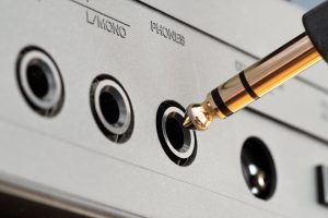
Типоразмеры
Разъемы jack имеют три форм-фактора по размерам: 2,5 мм, 3,5 мм и 6,35 мм.
Mini-jack
Это самый массовый вариант. Диаметр коннектора и гнезда – 3,5 мм. С помощью mini-jack разновидности TRS наушники подключают к системной плате персональных компьютеров, а также к звуковым картам потребительского уровня.
Разъем 3,5 мм, но в варианте TRRS используется на большинстве современных смартфонов и планшетов на базе Android, Linux и Windows. В ноутбуках могут встречаться 3,5 мм гнезда, рассчитанные либо на TRS, либо на TRRS подключение.
Jack
У этого разъема самый большой диаметр в семействе – 6,35 мм. Сегодня он востребован в исполнении TRS как интерфейс для наушников профессионального класса. Кроме того, разъем 6,35 мм можно найти в устаревших моделях наушников, что не отличаются качеством воспроизведения. В них jack применялся только потому, что не было компактных разновидностей, они появились намного позже.
Наушники профессионального уровня через переходник можно подключить к любым современным устройствам. Однако предназначены они для использования вместе с техникой соответствующего уровня, главным образом с профессиональными звуковыми картами.
Micro-jack
Этот типоразмер довольно редкий, диаметр гнезда и штекера составляет всего 2,5 мм. Его используют для подключения гарнитуры к некоторым видам портативной техники. На телефонах Nokia времен слайдеров micro-jack был типичным решением. В современных наушниках таких известных брендов, как Audio-Technica, AKG, Bose, Sennheiser, его используют на съемных шнурах со стороны подключения к динамику.
Распиновка
Распиновка – это распределение линий передачи относительно контактных площадок. Существует два стандарта TRRS:
- OpenMobileTerminalPlatform (OMTP) – каналы распределены так: T – левый динамик, R1 – правый, R2 – микрофон, S – земля или минус.
- CellularTelephoneIndustriesAssociationLightning (CTIA) – контакты располагаются иначе: земля и микрофон меняются местами.
Первый вариант распиновки характерен для устройств, выпущенных до 2012 года, после появился новый стандарт.
Если подключить OMTP-гарнитуру старого образца к новому CTIA-разъему в левый и правый динамики будет поступать одинаковый глухой монозвук. Он воспроизводит разницу между правым и левым каналами. Так происходит потому, что оставшиеся контактные площадки расположены в обратном порядке, канала земли нет. При этом, если включить микрофон, канал R2 замыкается и начинает выступать в роли минуса, переводя воспроизведение в режим стерео.
Существует и третий вариант распиновки, его называют балансным подключением TRS:
- T – плюс, или горячий (положительный) сигнал;
- R – минус, или холодный (отрицательный) сигнал;
- S – земля.
Такой стандарт, как правило, реализуется в профессиональных наушниках с диаметром разъема 6,35 мм.
XLR
С балансной схемой, подобной описанной выше, есть альтернативный разъем – XLR. Его широко используют в мире первоклассного аудиооборудования, но больше не устанавливают в устройства потребительского уровня.
Штекер интерфейса представляет собой три штырьковых контакта, что расположены в вершинах воображаемого треугольника и окружены металлической рубашкой полого цилиндра. Гнездо соответствует ему по форме.
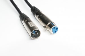
Lightning
Вся новая продукция Apple, начиная с iPhone 5, iPad Mini и iPod Nano, использует для подключения проводных наушников разъем Lightning. В отличие от jack это не аналоговый, а цифровой интерфейс. Это значит, что цифро-аналоговый преобразователь (ЦАП), который переводит двоичный сигнал в электромагнитные колебания для динамиков, может располагаться непосредственно в наушниках. Это позволяет производителю делать блок максимально адаптированным к собственному оборудованию и гарантировать лучшее качество звука.
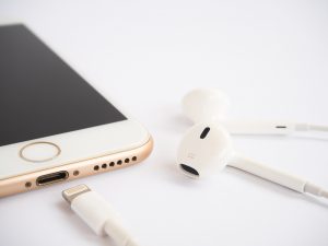
Разъемы для наушников на разной электронике и способы подключения
Компьютеры, ноутбуки, телефоны и другие мультимедийные устройства имеют очень разнообразные способы подключения периферии, в том числе наушников.
Стационарные ПК
На задней панели системной платы компьютеров устанавливают разъемы mini-jack формата TRS, их может быть от трех до шести. В первом случае передается двухканальный звук, назначение каждого гнезда определяется по цвету:
- зеленый – выход;
- синий – вход;
- розовый – микрофон.
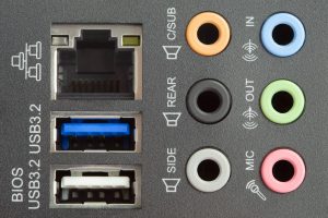
Компьютерные наушники со штекером TRS подключаются к одному зеленому разъему – выходу. Игровые гарнитуры имеют два коннектора – звуковой и микрофонный. Некоторые гарнитуры со штекером TRRS для соединения с ПК нуждаются в переходнике с четырехконтактным гнездом с одной стороны и двумя трехконтактными штекерами с другой.
Большее количество гнезд mini-jack на задней стенке говорит о том, что встроенная логика системной платы может воспроизводить и передавать звук в формате 5.1 или 7.1, то есть в шести- и восьмиканальном соответственно. Для подключения наушников служат те же гнезда зеленого и розового цветов.
Ноутбуки
На ноутбуках и ультрабуках встречаются те же разъемы диаметром 3,5 мм, но в одном из двух вариантов:
- два TRS – гнезда наушников и микрофона обозначаются пиктограммами устройств;
- один TRRS, к которому можно подключить либо телефонную гарнитуру, либо компьютерную, но уже через обратный переходник с четырехконтактным штекером и двумя трехконтактными гнездами.
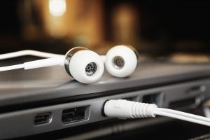
Такие переходники для соединения разных разъемов наушников и мультимедиатехники можно найти в продаже в отделах радиоэлектроники или заказать в интернет-магазине, например, на AliExpress. Нетрудно и спаять их самостоятельно, приобретя соответствующие штекеры и гнезда и следуя распиновке.
Смартфоны и другая мобильная техника
Почти все современные телефоны, планшеты и большинство нетбуков оснащаются гнездом TRRS. Подключение аналогично описанному выше варианту с одним гнездом для ноутбуков.
Встречаются также телефоны с единственным гнездом USB-C, для которого выпускают наушники с Type-разъемом. У многих известных брендов в продаже есть линейки подобных устройств собственной разработки, например: Shure AONIC 50, Xiaomi ANC, OnePlus USB-C Bullets, Razer Hammerhead ANC, 1More Dual Driver ANC Pro. Подробнее о стандарте USB в отдельном тематическом разделе.
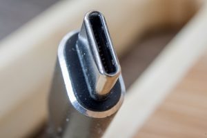
Телевизоры
Чтобы подключить разъем наушников к телевизору, почти в всегда нужен переходник mini-jack TRRS – RCA. Бывают крайне редкие исключения, когда на телевизоре присутствует разъем 3,5 мм.
Как подключить наушники, если нет разъема 3,5 мм
Если у вас наушники с каким-либо штекером вида jack, но вы хотите подключиться к устройству, у которого нет подходящего гнезда, остается воспользоваться переходником или адаптером.
Чтобы подключить не Lightning-наушники к продукции Apple, используйте переходники TRS mini-jack. Они входят в комплект таких смартфонов, как iPhone 7/Plus, iPhone 8/Plus/X и других.
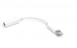
Нюансы подключения наушников через USB
Все наушники со стандартным прямоугольным USB-штекером оснащены собственной звуковой картой, необходимой для преобразования цифрового сигнала в аналоговый. Поэтому, подключая их к компьютерам, ноутбукам и планшетам с USB-портами, нужно также установить соответствующий драйвер. В Windows 10 и 11, если есть доступ к интернету, установка почти всегда совершается автоматически, как только штекер наушников соединяют с компьютером. При этом гарнитуры с функцией объемного звука чаще всего определяются как два отдельных устройства: наушники и микрофон.
С ОС Android могут возникнуть сложности, если у гарнитуры продвинутая звуковая карта. Кроме того, для подключения понадобится кабель OTG, который выполняет роль переходника между USB-штекером и разъемом micro-USB смартфона или планшета.
Стоит также упомянуть разъем USB Type-C, в котором предусмотрена передача не только цифрового сигнала, но и аналогового. В продаже есть наушники со штекерами Type-C, готовые работать с электромагнитной частотой напрямую, однако не всегда в устройствах, к которым они будут подключены, есть встроенный ЦАП. Поэтому лучше приобретать гарнитуры USB-C с собственной звуковой картой.
Что делать, если стационарный ПК или ноутбук не видят разъем наушников
Определите причину возникшей проблемы. Прежде всего проверьте корректность подключения. Стоит выяснить следующее:
- соответствует ли штекер разъему;
- вставлен ли штекер в разъем до упора;
- исправен ли кабель наушников.
Если при подключении USB-гарнитуры операционная система видит, но не может определить тип устройства, необходимо установить драйвер. Его можно загрузить с сайта производителя.
Часто наушники и гарнитура выходят из строя из-за повреждения кабеля в местах соединения со штекером.
Ремонт разъема на наушниках
В дорогих моделях наушников коннектор может разбираться. В таком случае восстановить нарушенное соединение просто. Достаточно добраться до контактов и подпаять отсоединившийся провод.
В устройствах бюджетного и среднего класса у штекера чаще всего неразборная конструкция. Чтобы получить доступ к контактам, придется срезать пластик. Сделать это возможно, но быстрее, проще и эстетичнее приобрести и присоединить новый штекер.
Замена разъема на наушниках
В магазинах радиотехники можно отдельно купить штекер любого формата в разборном корпусе. Останется обрезать вышедший из строя коннектор, зачистить провода и припаять к контактам нового.
Подводя итоги
Наиболее популярный тип разъемов наушников – jack, что может быть представлен в трех размерных форматах. Встречаются также разъемы USB и USB-C, а у техники Apple есть собственный интерфейс – Lightning. Наушники, что относятся к профессиональной аудиоаппаратуре, могут иметь разъем XLR.
Разъём TRS (phone connector) по кличке «джек» разработан для передачи аналогового звука и чаще всего применяется в наушниках,…
Разъём TRS (phone connector) по кличке «джек» разработан для передачи аналогового звука и чаще всего применяется в наушниках, гарнитурах и колонках.
TRS значит:
Tip — наконечник,
Ring — кольцо,
Sleeve — гильза.
Слово «jack» в аудиотехнике значит «гнездо», поэтому некорректно называть «джеком» штекер, а то и целый класс коннекторов. Кроме жаргонизма «джек» встречаются названия: «аудио» и «стерео».
Модификации разъёма TRS «джек»
Количество контактов ▼
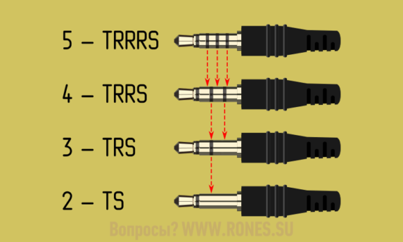
• 5 контактов — TRRRS «jack 5-pole». Применяется в гарнитурах с шумоподавлением.
• 4 контакта — TRRS «jack 4-pole». Применяется в обычных гарнитурах, в балансных наушниках, в соединительных шнурах ТВ-приставок и в некоторых экзотических переходниках.
• 3 контакта — TRS «stereo» или «jack 3-pole». Применяется в шнурах наушников, колонок и микрофонов.
• 2 контакта — TS «mono» или «jack 2-pole». Двухполюсный штекер применяется в профессиональной аппаратуре, например, для подключения электрогитар.
Типоразмеры ▼
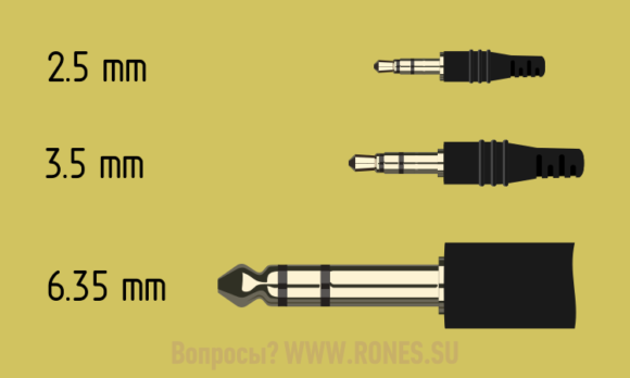
• 2.5 mm — микро-джек (малогабаритные гаджеты, гарнитуры старых мобильников)
• 3.5 mm — мини-джек (смартфоны, плееры, аудиокарта ПК)
• 6.35 mm — четверть дюйма — 1/4″ (эстрадный микрофон, профессиональные наушники)
Если размер штекера не подходит под размер гнезда, нужен переходник ▼
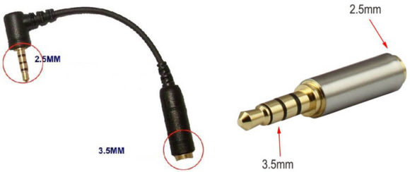
Распиновки штекера TRS
Нумерация контактов штекера TRS начинается с наконечника.
Назначение контактов TRS в наушниках и колонках задано чётко ▼
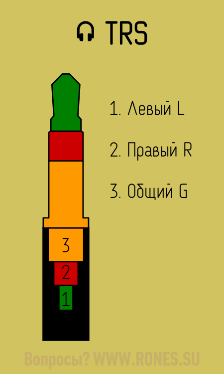
1 — Левый канал — L
2 — Правый канал — R
3 — Общий провод — G
По цветовой маркировке проводов в шнуре стандарта нет, но сложилась определённая традиция:
1 — Левый канал — Белый (или зелёный)
2 — Правый канал — Красный
3 — Общий провод — Медный (оплётка)
Кроме штекеров под пайку встречаются и штекеры под винт ▼

Распиновка штекера компьютерного монофонического микрофона ▼
Левый и правый контакты спаяны вместе — это собственно выход микрофона. Ну, а общий провод на своём законном месте.
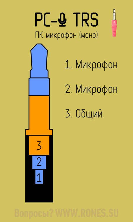
Распайка петличного микрофона (для подключения к смартфону) отличается от распайки компьютерного микрофона ▼
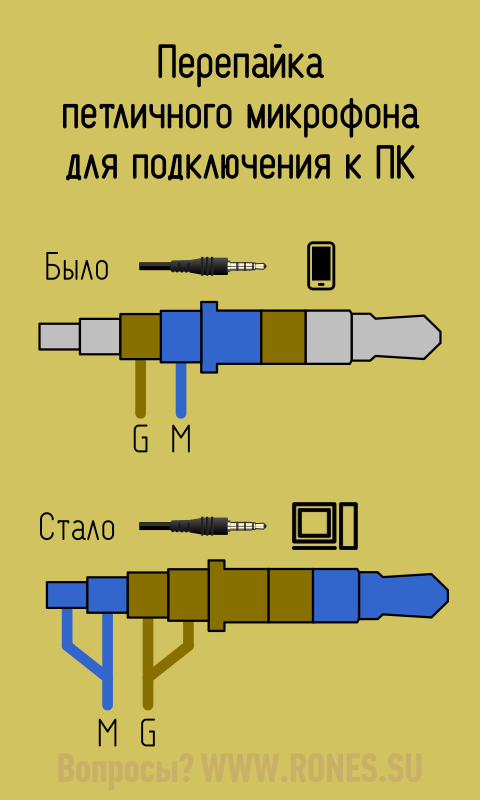
Подробнее о подключении микрофонов и гарнитур к компьютеру или смартфону — в статье «Микрофоны, наушники и гарнитура»
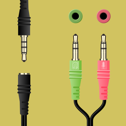
Распиновки штекера TRRS
Распиновка штекера TRRS зависит от области применения. На каждый случай написана отдельная статья ▼
• Гарнитуры мобильников и смартфонов. См. также все варианты распайки гарнитур ▼
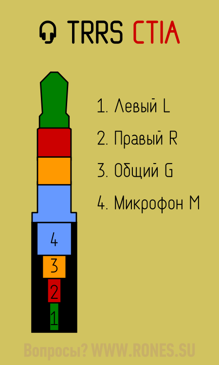
• Балансные наушники ▼
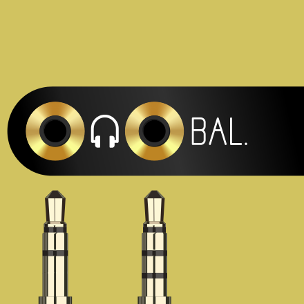
• Переходники на RCA «тюльпаны» для ТВ-приставок ▼
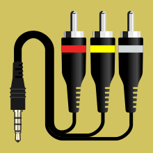
• Дата-кабели для миниатюрных плееров и умных часов ▼
⚠ Эти переходники не используются для передачи звука! Штекер TRRS используется в них не по назначению.
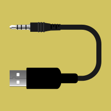
Распиновка гнёзд TRS и TRRS
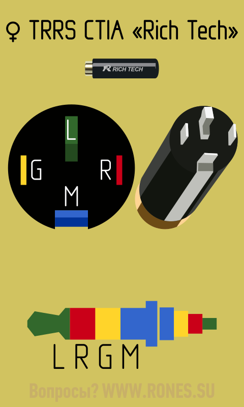
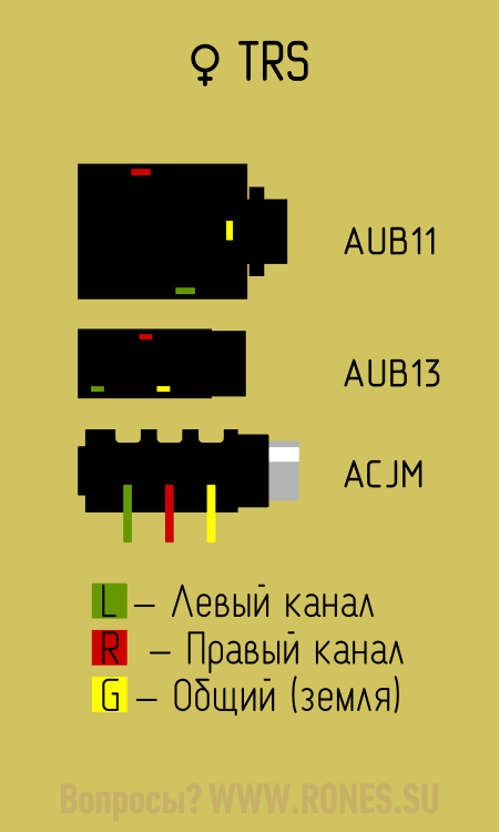
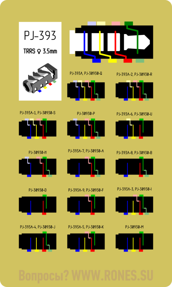
Обратите внимание — некоторые гнёзда снабжены контактами на размыкание. Это придумано для того, чтоб при подключении наушников к ПК или магнитофону отключались динамики. При подключении штекера к такому гнезду, контакты левого и правого канала размыкаются, тем самым отключая динамики ▼
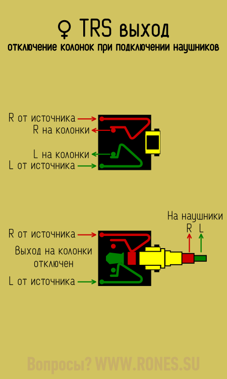
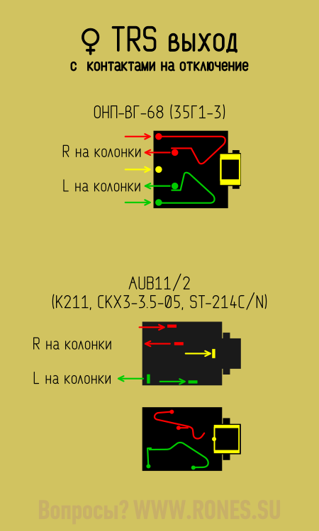
Если это отключение вас не устраивает, необходимо впаять перемычки ▼
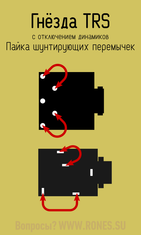
Контактами на размыкание оборудуется и линейный вход. При подключении к магнитоле внешнего источника звука, отключается внутренний источник (напр. радио) ▼

Переходник с «джека» на «колокольчики»
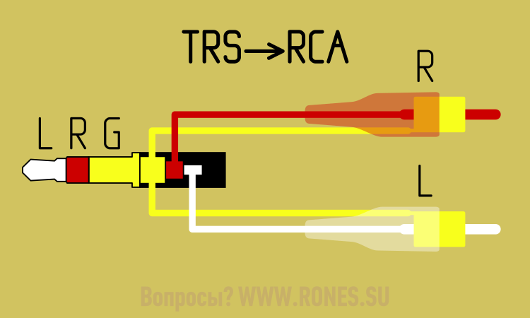
Все материалы по теме «Аудио»
Все материалы по теме «Гарнитура»
Если материал оказался полезным для вас…
…вы можете нас отблагодарить! Авторам сайта будет очень приятно!