GSM модули находят широкое применение в современных радиоэлектронных проектах. Достаточно много подобных проектов рассмотрено и на нашем сайте. Но вместо покупки GSM модуля, цены на которые непрерывно растут в условиях современного дефицита электронных компонентов, в подобных проектах можно использовать и старый сотовый телефон, которых наверняка скопилось у вас дома как минимум несколько штук.
 В данной статье мы рассмотрим подключение к плате Arduino старого сотового телефона и будем его использовать вместо GSM модуля для осуществления некоторых функций приема данных.
Общие принципы работы проекта
Непосредственное извлечение GSM модуля из старого сотового телефона в большинстве случаев представляет собой весьма нетривиальную задачу, на решение которой можно потратить много сил и времени. Поэтому в данном проекте мы применим несколько другой подход.
Когда сотовый телефон принимает вызов или SMS, он светится, жужжит или издает какие либо другие звуки. И мы это можем использовать в Arduino. Мы можем подключиться к двигателю телефона, который используется для его вибрации, поэтому мы сможем отслеживать моменты когда на него подается питание – а это случается когда телефон получает SMS или телефонный звонок.

Конечно, подобное решение не является полноценной заменой GSM модуля, при помощи которого мы могли бы считывать все принимаемые данные и осуществлять передачу данных (к примеру, из платы Arduino с помощью GSM модуля можно сделать полноценный сотовый телефон), но определенную пользу из такого решения все таки можно извлечь. Например, что бы удаленно включать/выключать какой-нибудь насос или другой исполнительный механизм нам, в принципе, не важно содержание поступающих SMS – при первой SMS мы можем его включать, при второй – выключать, при третьей – снова включать и т.д.
Для реализации данного проекта нам понадобятся всего лишь плата Arduino Uno (купить на AliExpress), светодиод, сим-карта и старый сотовый телефон. Внешний вид этих компонентов показан на следующих рисунках.


В этом проекте при поступлении SMS на сотовый телефон мы будем включать светодиод, подключенный к плате Arduino. При желании, я думаю, вы данный проект легко сможете адаптировать под свои потребности.
 Подключение к двигателю сотового телефона
Далее нам необходимо получить доступ к двигателю сотового телефона, который используется для его вибрирования (rumble motor). Для различных телефонов доступ к этому двигателю будет отличаться, но при помощи визуального осмотра и, при необходимости, использования поиска в сети интернет, я думаю, вы без проблем сможете найти этот двигатель в телефоне.
 После этого нам необходимо припаять два провода к контактам этого двигателя. Поскольку эти двигатели во многих моделях телефонов очень миниатюрные, то для этой цели желательно использовать минимальное количество припоя и очень тонкие провода.

Затем, когда эти провода будут припаяны к контактам двигателя, нам необходимо подключить к ним мультиметр. Делается это для двух целей. Первая – узнать величину напряжения, возникающую на этих контактах. Вторая – определить какой контакт является положительным, а какой отрицательным.
 Автор проекта (ссылка на оригинал приведена в конце статьи) использовал для этого свой старый телефон blackberry и с помощью мультиметра определил, что на этих контактах формируется напряжение примерно 1.5 В, что вполне подходит для подключения к Arduino.
Схема проекта
Схема подключения сотового телефона вместо GSM модуля к Arduino представлена на следующем рисунке.
 Как видите, схема достаточно проста. Контакт земли двигателя (ground pin) нам необходимо подключить к контакту земли платы Arduino, а положительный контакт (positive pin) двигателя – к контакту A0 платы Arduino. Также необходимо подключить катод (-) светодиода к контакту земли платы Arduino, а анод (+) светодиода – контакту 7 платы.
Исходный код программы (скетча)
Код программы также очень простой. Контакт 7 платы Arduino у нас работает как цифровой выход. А на контакте A0 мы будем считывать напряжение с выхода двигателя сотового телефона и сохранять его в переменной sensorValue. Если значение sensorValue будет больше 50 мы будем подавать логическую единицу на контакт 7, в результате чего будет загораться светодиод, подключенный к данному контакту. Если значение sensorValue будет меньше или равно 50, мы будем выключать светодиод. Также через последовательный порт мы будем передавать сообщения «Rumble on» и «Rumble off», которые будут сигнализировать о состоянии двигателя сотового телефона.
| 1 2 3 4 5 6 7 8 9 10 11 12 13 14 15 16 17 18 19 20 | void setup() { Serial.begin(9600); pinMode(7, OUTPUT); } void loop() { int sensorValue = analogRead(A0); if (sensorValue > 50) { digitalWrite(7, HIGH); Serial.println(«Rumble on»); delay(1000); } else { digitalWrite(7, LOW); Serial.println(«Rumble off»); delay(100); } } |
Тестирование работы проекта
Когда проект будет полностью готов к работе, то при передаче SMS на сотовый телефон будет подаваться сигнал на двигатель, включающий режим вибрации (rumble motor), плата Arduino будет считывать этот сигнал, включать светодиод и передавать сообщение “Rumble On” через последовательный порт.
 Автор проекта планирует в будущем использовать подобное решение для включения/выключения света в комнате с помощью SMS.
Видео, демонстрирующее работу проекта
Источник статьи
![]() Загрузка…
Загрузка…
687 просмотров
Introduction: My Old Phone + Arduino = Phonoduino
Hi, this is a project of my old Nokia 1100 phone and arduino mega. By using this many arduino and gsm based project is possible. The phone will work like a gsm module and you can sent message or call someone by using this phonoduino. You can also receive DTMF signal and control anything remotely. It can be used for home automation, home security and monitoring, bird feeder or anything you like. You can also type sms by computer keyboard and send instantly to someone or group by using arduino serial monitor. If you used multimedia phone instead of nokia 1100 you can sent image to another mobile or e-mail by this project. Following are the step by step guide for making the thing.
Phonoduino can be a best DIY for remote monitoring, security and control.
Step 1: Required Components
1. Old but working phone (I am using nokia 1100 but other phone will also work without touch phone)
2. Arduino Mega (UNO has less number of pin and can be used if DTMF is not required)
3. General purpose NPN transistor (2N2222 or BC547 x 16)
3. DTMF decoder IC (M-8870)
4. Resistors (5.6kΩ x 16, 100kΩ; 70kΩ; 390kΩ)
5. Capacitors (0.1µFx 2)
6. Crystal oscillator (3.579545MHz)
7. Vero-board and some wire
Required Tools
1. Screw Driver
2. Soldering Iron
3. Wire Cutter
4. Knife
5. Multimeter
Step 2: Preparing the Phone
Open the casing of the phone. Remove the screw using screw driver. Then remove the plastic insulation above the keypad of the phone. Now solder thin insulated wire (I used connecting wire from old Hard disk IDE cable) to the signal pad of every button. Inner dot pad is signal pad and outer circular pad is ground pad. When soldering be careful DON’T SHORT GROUND PAD AND SIGNAL PAD WITH SOLDER. Now solder one wire with ground pad.
After soldering all button add the display with frame. Out the wire from the hole of display frame and adjust it to the motherboard with screw. Top metal of the display frame is connected to ground. Now connect the wire of the power button to the ground wire or just connect to the metal frame and hold for some moment. If every thing is correct the phone will be ON. Successfully ON your phone? Congratulation! You have completed first step.
Step 3: Connecting With Arduino Mega
Above schematic shows how arduino digital pins (D3 to D18) are connected to phone keys. I used general purpose bipolar npn transistor (2N2222) for switching (on-off the phone key). Any other general purpose npn transistor such as BC547, 548 may be used. Arduino digital I/O pin is connected to the base of transistor through a current limiting resistor. A 12k resistor works fine. When a digital pin of arduino become high the BJT turn on and work as like a press on the key of mobile phone. If you are interested to know more about transistor follow the link: https://learn.sparkfun.com/tutorials/transistors. You can find the datasheet of 2N2222 here. Pin configuration of 2N2222 is given above.
When connecting different circuit together for successful operation one thing must be remember, there must be one common ground connection among them whatever the other connection is. I connect phone ground and arduino ground together with the emitter of transistors. Image of transistors board is uploaded herewith. For connecting arduino I/O port I added male pin header to the board. Pin headers are connected with base resistors through yellow jumper wire.
After making the board now carefully connect phone’s keypad wire with the collectors of the transistors. I didn’t add any resistor between transistor collector and keypad wire because according to phone schematic a resistor is internally connected to the signal pin of keypad.
Step 4: DTMF Decoder for Remote Control and Home Automation
Required Component
1. MT8870D or CM8870 or HT9170 IC
2. Capacitor (0.1uF x 2, 15-20pF x 2)
3. Resistor (300K x 1, 100K x 2)
4. Crystal (3.579545MHz x 1)
5. Bread board
The circuit diagram of DTMF decoder/receiver is given above. Crystal is connected to pin 7 and 8. Two 20pf capacitor is connected between crystal and ground (it is not mandatory, you may not use pf capacitor or you may use any in range of 15pf — 30pf). For the resistor 100K you may use around 150K and for 300K around 400K may be used. Pin 5 & 6 should be connected to ground and pin 10 should be connected to vcc (this is not shown in schematic). For details see the datasheet of MT8870.
Image of my complete DTMF module is uploaded above. Pin configuration of Nokia headphone jack is given herewith. speaker +ive is connected to the pin 2 of the IC through 104pf (104pf = 0.1uf) capacitor and 100k series resistor. Speaker -ive is connected to ground. mic +ive and -ive will remain open. Head wires are insulated by different colored insulation. For soldering these wires to the pcb you have to remove the insulation. You can use sand paper or use match fire to burn the insulation. Put the terminal of the wire into fire for 2-3 seconds insulation will burn. Now you can solder the wire to pcb.
If you don’t like to take burden of making this DTMF module you can use Seeedstudio DTMF shield, a very cool one.
Want to know more about DTMF? click here
Step 5: Programming Arduino
Image of my complete phonoduino (phone + arduino) setup is given above. DTMF input is not given to the arduino now. We will see this later of this project. Let us now write some code to give the live of the phonoduino. Code for automatic calling for any given number is attached.
int key0 = 16;
int key1 = 6;
int key2 = 12;
int key3 = 9;
int key4 = 5;
int kry5 = 15;
int key6 = 10;
int key7 = 14;
int key8 = 13;
int key9 = 18;
int keyStar = 17;
int keyOk = 11;
int keyClear = 3;
int keyDown = 4;
int keyUp = 8;
int keyOff = 2;
int keyHash = 19;

int pressTime = 100;
int pressDelay = 300;
int holdTime = 1000;

int value[16] = {16,6,12,9,5,15,10,14,13,18,17,11,3,4,8,2};

void setup() {
  // initialize the digital pin as an output.
  for(int i=2; i<20; i++)
     pinMode(i, OUTPUT);

holdClear();

unlockPhone();
delay(2000);

holdClear();
delay(1000);
// call 0123456789
pressDigit(0);
pressDigit(1);
pressDigit(2);
pressDigit(3);
pressDigit(4);
pressDigit(5);
pressDigit(6);
pressDigit(7);
pressDigit(8);
pressDigit(9);

delay(100);
pressOk();

delay(5000);

}

// the loop routine runs over and over again forever:
void loop() {

}

void pressDigit(int digit){
   digitalWrite(value[digit], HIGH);  // press digit from 0 to 9
   delay(pressTime);
   digitalWrite(value[digit],LOW);
   delay(pressDelay);
}

void pressOk(){
   digitalWrite(keyOk, HIGH);  // press ok
   delay(pressTime);
   digitalWrite(keyOk,LOW);
   delay(pressDelay);
}

void pressClear(){
   digitalWrite(keyClear, HIGH);  // press clear
   delay(pressTime);
   digitalWrite(keyClear,LOW);
   delay(pressDelay);
}

void pressStar(){
   digitalWrite(keyStar, HIGH);  // press star
   delay(pressTime);
   digitalWrite(keyStar,LOW);
   delay(pressDelay);
}

void pressUp(){
   digitalWrite(keyUp, HIGH);  // press up
   delay(pressTime);
   digitalWrite(keyUp,LOW);
   delay(pressDelay);
}

void pressDown(){
   digitalWrite(keyDown, HIGH);  // press down
   delay(pressTime);
   digitalWrite(keyDown,LOW);
   delay(pressDelay);
}

void pressHash(){
   digitalWrite(keyHash, HIGH);  // press hash
   delay(pressTime);
   digitalWrite(keyHash,LOW);
   delay(pressDelay);
}

void pressOff(){
   digitalWrite(keyOff, HIGH);  // press off
   delay(pressTime);
   digitalWrite(keyOff,LOW);
   delay(pressDelay);
}

void holdOff(){
   digitalWrite(keyOff, HIGH);  // hold off
   delay(holdTime);
   digitalWrite(keyOff,LOW);
   delay(pressDelay);
}

void holdClear(){
   digitalWrite(keyClear, HIGH);  // press clear
   delay(holdTime);
   digitalWrite(keyClear,LOW);
   delay(pressDelay);
}

void unlockPhone(){
  pressOk();
  pressStar();
}
Want to call any number from serial monitor?
Code for calling from serial monitor is also attached. Just type phone number into terminal terminating with a coma (,) and press enter. Phonoduino will instantly dial the number. Coma indicates you just complete typing number and want to call. If you want to clear any number wrongly typed just type semicolon (;) and press enter. Then retype your number.
Want to send message from serial monitor?
Typing message from mobile phone is boring and time consuming. It will be easy to type sms from computer keyboard and will save lots of time. A sample arduino sketch is given to sent sms from serial monitor. Just upload the program to your arduino, open serial monitor, type your message, type colon(:), type number, type mobile number or any number you want to sent your sms and press enter key. Your phonoduino will sent the message to your desired number.
Example: Hello, I am from phonoduino.:123456789*
The above command will sent «Hello, i am from phonoduino.» to the number «123456789»
<code>
int pressTime = 100;
int pressDelay = 300;
int holdTime = 1000;
int typeTime = 100;
int typeDelay = 400;

int value[16] = {16,6,12,9,5,15,10,14,13,18,17,11,3,4,8,2};
char number[12];
char massegeChar[160];
int count = 0;
int numCount = 0;
int charDelay = 300;
int numberState = 0;
void setup() {
  // initialize the digital pin as an output.
  for(int i=2; i<20; i++)
     pinMode(i, OUTPUT);

Serial.begin(9600);
holdClear();

}

// the loop routine runs over and over again forever:
void loop() {
   while (Serial.available()>0){
        char character = Serial.read();
         if(character == '*'){
           sentSMS();
           count = 0;
           numCount = 0;
           numberState = 0;
           }
        if(character == ':'){
          numberState = 1;
          numCount = 0;
          //delay(10);
        }
        if(numberState == 1){
         number[numCount] = character;
         numCount++;
        }
        if(numberState == 0){
         massegeChar[count] = character;
         count++;
        }
        if(character == '#'){
           count = 0;
           numberState = 0;
        }
      }

}

void pressDigit(int digit){
   digitalWrite(value[digit], HIGH);  // press digit from 0 to 9
   delay(pressTime);
   digitalWrite(value[digit],LOW);
   delay(pressDelay);
}

void pressOk(){
   digitalWrite(keyOk, HIGH);  // press ok
   delay(pressTime);
   digitalWrite(keyOk,LOW);
   delay(pressDelay);
}

void pressClear(){
   digitalWrite(keyClear, HIGH);  // press clear
   delay(pressTime);
   digitalWrite(keyClear,LOW);
   delay(pressDelay);
}

void pressStar(){
   digitalWrite(keyStar, HIGH);  // press star
   delay(pressTime);
   digitalWrite(keyStar,LOW);
   delay(pressDelay);
}

void pressUp(){
   digitalWrite(keyUp, HIGH);  // press up
   delay(pressTime);
   digitalWrite(keyUp,LOW);
   delay(pressDelay);
}

void pressDown(){
   digitalWrite(keyDown, HIGH);  // press down
   delay(pressTime);
   digitalWrite(keyDown,LOW);
   delay(pressDelay);
}

void pressHash(){
   digitalWrite(keyHash, HIGH);  // press hash
   delay(pressTime);
   digitalWrite(keyHash,LOW);
   delay(pressDelay);
}

void pressOff(){
   digitalWrite(keyOff, HIGH);  // press off
   delay(pressTime);
   digitalWrite(keyOff,LOW);
   delay(pressDelay);
}

void holdOff(){
   digitalWrite(keyOff, HIGH);  // hold off
   delay(holdTime);
   digitalWrite(keyOff,LOW);
   delay(pressDelay);
}

void holdClear(){
   digitalWrite(keyClear, HIGH);  // press clear
   delay(holdTime);
   digitalWrite(keyClear,LOW);
   delay(pressDelay);
}

void typeA(){
  digitalWrite(key2, HIGH);
  delay(typeTime);
  digitalWrite(key2, LOW);
  delay(typeDelay);
}
void typeB(){
  typeA();
  typeA();
}
void typeC(){
  typeA();
  typeA();
  typeA();
}
void typeD(){
  digitalWrite(key3, HIGH);
  delay(typeTime);
  digitalWrite(key3, LOW);
  delay(typeDelay);
}
void typeE(){
  typeD();
  typeD();
}
void typeF(){
  typeD();
  typeD();
  typeD();
}
void typeG(){
  digitalWrite(key4, HIGH);
  delay(typeTime);
  digitalWrite(key4, LOW);
  delay(typeDelay);
}
void typeH(){
  typeG();
  typeG();
}
void typeI(){
  typeG();
  typeG();
  typeG();
}
void typeJ(){
  digitalWrite(key5, HIGH);
  delay(typeTime);
  digitalWrite(key5, LOW);
  delay(typeDelay);
}
void typeK(){
  typeJ();
  typeJ();
}
void typeL(){
  typeJ();
  typeJ();
  typeJ();

}
void typeM(){
  digitalWrite(key6, HIGH);
  delay(typeTime);
  digitalWrite(key6, LOW);
  delay(typeDelay);
}
void typeN(){
  typeM();
  typeM();
}
void typeO(){
  typeM();
  typeM();
  typeM();

}
void typeP(){
  digitalWrite(key7, HIGH);
  delay(typeTime);
  digitalWrite(key7, LOW);
  delay(typeDelay);
}
void typeQ(){
  typeP();
  typeP();
}
void typeR(){
  typeP();
  typeP();
  typeP();

}
void typeS(){
  typeP();
  typeP();
  typeP();
  typeP();
}
void typeT(){
  digitalWrite(key8, HIGH);
  delay(typeTime);
  digitalWrite(key8, LOW);
  delay(typeDelay);
}
void typeU(){
  typeT();
  typeT();
  typeT();
}
void typeV(){
  typeT();
  typeT();
  typeT();

}
void typeW(){
  digitalWrite(key9, HIGH);
  delay(typeTime);
  digitalWrite(key9, LOW);
  delay(typeDelay);
}
void typeX(){
  typeW();
  typeW();
}
void typeY(){
  typeW();
  typeW();
  typeW();

}
void typeZ(){
  typeW();
  typeW();
  typeW();
  typeW();
}
void space(){
  digitalWrite(key0, HIGH);
  delay(typeTime);
  digitalWrite(key0, LOW);
  delay(typeDelay);

}
void sentSMS(){
 holdClear();

 holdClear();
 pressOk();
 pressOk();
 pressOk();
 for(int i = 0; i< 160; i++){
   switch(massegeChar[i]){
     case 'A':
     case 'a':
     typeA();
     delay(charDelay);
     break;

     case 'B':
     case 'b':
     typeB();
     delay(charDelay);
     break;

     case 'C':
     case 'c':
     typeC();
     delay(charDelay);
     break;

     case 'D':
     case 'd':
     typeD();
     delay(charDelay);
     break;

     case 'E':
     case 'e':
     typeE();
     delay(charDelay);
     break;

     case 'F':
     case 'f':
     typeF();
     delay(charDelay);
     break;

     case 'G':
     case 'g':
     typeG();
     delay(charDelay);
     break;

     case 'H':
     case 'h':
     typeH();
     delay(charDelay);
     break;

     case 'I':
     case 'i':
     typeI();
     delay(charDelay);
     break;

     case 'J':
     case 'j':
     typeJ();
     delay(charDelay);
     break;

     case 'K':
     case 'k':
     typeK();
     delay(charDelay);
     break;

     case 'L':
     case 'l':
     typeL();
     delay(charDelay);
     break;

     case 'M':
     case 'm':
     typeM();
     delay(charDelay);
     break;

     case 'N':
     case 'n':
     typeN();
     delay(charDelay);
     break;

     case 'O':
     case 'o':
     typeO();
     delay(charDelay);
     break;

     case 'P':
     case 'p':
     typeP();
     delay(charDelay);
     break;

     case 'Q':
     case 'q':
     typeQ();
     delay(charDelay);
     break;

     case 'R':
     case 'r':
     typeR();
     delay(charDelay);
     break;

     case 'S':
     case 's':
     typeS();
     delay(charDelay);
     break;

     case 'T':
     case 't':
     typeT();
     delay(charDelay);
     break;

     case 'U':
     case 'u':
     typeU();
     delay(charDelay);
     break;

     case 'V':
     case 'v':
     typeV();
     delay(charDelay);
     break;

     case 'W':
     case 'w':
     typeW();
     delay(charDelay);
     break;

     case 'X':
     case 'x':
     typeX();
     delay(charDelay);
     break;

     case 'Y':
     case 'y':
     typeY();
     delay(charDelay);
     break;

     case 'Z':
     case 'z':
     typeZ();
     delay(charDelay);
     break;

     case ' ':
     space();
     break;
   }
  delay(300);
 }
  pressOk();
  pressOk();
  callNumber();
}

void callNumber(){
  for(int i=1; i<12; i++){
    pressDigit(number[i]-'0');  // number[i] - '0' is for converting character into intiger
  }
 pressOk();
 holdClear();
 holdClear();
}
I will published a more efficient arduino sketch later.
Step 6: Home Security and Automation Using Cell Phone
You can control your home appliances or another thing using this project or you can use it for security purpose. A simple demo will be given here. I have set a ultrasonic sensor to arduino. Our previously made DTMF module is also connected to the phone. When something come in front from ultrasound sensor phonoduino dial the number u previously set. After receiving the call I am controlling an LED (it can be anything you like). Let you set the ultrasound sensor in front of your door. When you are outside and then someone come in front of the door, phonoduino will call you and receiving the call you can open the door for your guest or ring an alarm for the thief.
The sample code is given an a video is uploaded.
Step 7: Conclusion
This project is made for Seeed rephone contest. I will published more project using this phonoduino in future. Thank you, and I am apologized for my weak English.
If you have any query or need any help please comment and let me know your problem (or message me) and I’ll try my best to help you.
Be the First to Share
Recommendations
Многие часто занимаются проектами в области беспроводной связи, в основном, основанными на модуле Bluetooth. Но после того как в работе над проектами возникает необходимость использования SMS или телефонных звонков, то здесь помогает использование GSM-модулей. Однако, сразу возникает большая проблема… они довольно дорогие!
Хорошо что в такие моменты в голову приходят правильные мысли, а одна из них сообщала о том, что телефон — это всего лишь GSM-модуль с большим количеством функций. Наверняка у каждого есть несколько телефонов, которые просто лежат в ящике без какой-либо надобности. Таким образом, мы можем использовать один из них в качестве GSM-модуля и это то, что мы будем делать в этом уроке.
Содержание
- Шаг 1. В чем идея?
- Шаг 2. Список комплектующих
- Шаг 3. Использование телефона
- Шаг 4. Принципиальная схема
- Шаг 5. Код проекта
- Шаг 6. Результат
Шаг 1. В чем идея?


Фактически, спасти GSM-модуль от телефона очень сложно и потребуется много времени и навыков, поэтому в этом проекте мы будем придерживаться немного другого подхода.
Всякий раз, когда телефон получает SMS или телефонный звонок, он либо загорается, либо гудит/вибрирует, либо издает звук. Зная это, мы сможем воспользоваться этими функциями с помощью Arduino. Мы сделаем это, используя двигатель, который нужен для того, чтобы заставить телефон вибрировать. Arduino прочитает данные и посмотрит, когда двигатель работает, что именно получает телефон — SMS или телефонный звонок.
Это, конечно, не так хорошо и идеально, как наличие реального GSM-модуля, благодаря которому вы можете видеть, какие данные поступают или можете отправлять данные, но это дешевый вариант, если у вас есть куча телефонов, просто лежащих в ящике стола.
Шаг 2. Список комплектующих

Это довольно простой проект, поэтому нам не нужно много деталей, все, что нам нужно, это следующее:
- Arduino Uno
- Любой старый телефон
- Светодиоды
- Сим-карта
Когда будут выполнены все шаги по настройке проекта мы заставим мигать светодиод, когда телефон получит SMS-сообщение.
Мы сделали это для того, чтобы понять суть. В будущем проекте мы используем данную схему для управления освещением в комнате.
Шаг 3. Использование телефона

Цель этого шага состоит в том, чтобы разобрать телефон до такой степени, которая позволит получить доступ к двигателю управляющего вибрацией.
Минус в том, что для каждого телефона своя схема и своя структура. Но по большей части вы можете просто найти номер детали конкретного телефона в Яндексе или Гугле, чтобы увидеть, где находится двигатель.

Как только вы его найдете, вам понадобится припаять два провода к каждой клемме двигателя. Это может быть сложной задачей, так как на большинстве телефонов используются крошечные компоненты для поверхностного монтажа, фишка состоит в том, чтобы использовать минимальное количество припоя и очень тонкие провода.
Как только провода припаяны, нужно подключить их к мультиметру по двум причинам:
- во-первых, мы хотим узнать, какое напряжение дает телефон,
- во-вторых, выяснить, какой провод отрицательный и какой положительный.
В нашем случае мы обнаружили, что телефон дает около 1,5 вольта на двигатель, с которыми отлично справится Arduino.
Шаг 4. Принципиальная схема

Схема соединения довольно простая. Всё что нам нужно сделать, — это соединить все, как показано на рисунке выше.
Вывод заземления на двигателе подключается к заземляющему контакту на Arduino, после чего положительный контакт на двигателе подключается к A0 на Arduino, а затем, наконец, катод (-) светодиода подключается к земле на Arduino и анод (+) подключается к контакту 7. Далее мы можем загрузить код.
Шаг 5. Код проекта
Код также очень прост и его довольно легко понять. Скачать или скопировать код можно ниже:
void setup() {
  Serial.begin(9600);
  pinMode(7, OUTPUT);
}

void loop() {
  int sensorValue = analogRead(A0);
  if (sensorValue > 50)
{
  digitalWrite(7, HIGH);
  Serial.println("Rumble on");
delay(1000);
}
else
{
  digitalWrite(7, LOW);
  Serial.println("Rumble off");
delay(100);
}
}
В настройке void мы говорим, что вывод 7 будет выступать в качестве выходного сигнала, так как это будет наш светодиодный вывод. Затем в цикле void, мы говорим, что sensorValue является аналоговым значением pin A0, которое затем используется в выражении if.
Оператор if утверждает, что если sensorValue больше 50, то включить контакт 7, который является светодиодным выводом, и отправить обратно «Rumble On» на последовательный монитор. Если значение sensorValue меньше 50, то выключить светодиод и отправить обратно «Rumble Off» на последовательный монитор.
Откройте код в IDE Arduino, загрузите его на свою плату и протестируйте.
Шаг 6. Результат

Итак, теперь когда мы собрали всё вместе давайте посмотрим как это работает.
Когда мы отправляем на телефон SMS, он посылает сигнал на двигатель, управляющий вибрацией, который затем посылает сигнал на Arduino. Далее включается светодиод и отправляется «Rumble On» на последовательный монитор.
Далее мы можем усложнять проекты. Так, например, мы можем включать свет в доме после того как мы направляем СМС на телефон. Такого рода проекты мы как правило публикуем в рубрике «Умный дом», где мы постепенно автоматизируем процессы управления различной техникой в доме.
19 ноября 2018 в 01:32
| Обновлено 7 декабря 2019 в 00:11 (редакция)
Опубликовано:
Уроки, Arduino
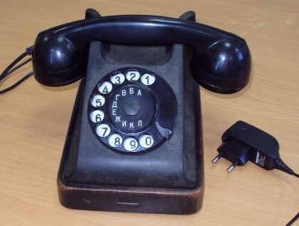
Немногие современные школьники видели стационарный телефон с дисковым номеронабирателем, и уж тем более, умеют им пользоваться. Стационарная телефонная связь уходит в прошлое. В статьях: Ретро GSM телефон на Arduino 1958 года, с дисковым номеронабирателем и Учим старый дисковый телефон работать в GSM сетях уже были описаны проекты создания стационарного сотового телефона, но в первой статье, проект собирается на Piranha UNO с так называемыми Shield-ами, а вторая статья содержит ошибки в приведенной схеме и «сырой» скетч. Я попытался обобщить опыт вышеуказанных авторов, и создать простой проект стационарного сотового телефона на базе Arduino Nano, который сможет повторить даже школьник на занятиях радиокружка.
Принципиальную схему телефона вы можете увидеть ниже. Как я уже писал выше, основу проекта составляет Arduino Nano и sim-модуль SIM800L. Необходимо отметить, что в проекте можно использовать практически любой сим-модуль, умеющий работать с голосовыми вызовами, так как скетч не содержит каких-то специальных библиотек, привязанных к конкретному сим-модулю, но следует обратить внимание на организацию питания такого модуля. Для нормальной работы SIM800L требуется 4,2-4,4 вольт; при более низком напряжении (при питании от сетевого источника) модуль работает не стабильно. Так как схема рассчитана на питание от сетевого источника +5вольт (1А), то для понижения питания до необходимых сим-модулю 4,4в применен диод VD2, с подобранным падением напряжения на нем примерно 0,6в. При использовании источника питания с несколько большим выходным напряжением, может понадобиться поставить в схему питания последовательно второй диод VD3 (подбирается при сборке схемы). Для компенсации пиковых нагрузок в цепи питания сим-модуля установлен конденсатор C1 емкостью 1000-2200 мкф. На резисторах R4, R6 собран резистивный делитель напряжения для согласования логических уровней TX-RX ардуино и сим-модуля, на линии RX-TX установлен резистор R5. Если используется сим-модуль с питанием +5вольт, резисторы R4-R6 не ставятся. При достаточном питании и вставленной сим-картой, модуль несколько секунд часто моргает красным светодиодом, а затем, при успешной регистрации в сети, частота моргания светодиода — примерно 1 раз в секунду. В большинстве случаев прекрасно работает штатная антенна-пружинка, для использования телефона в зоне неуверенного приема — установить дополнительную GSM-антенну в штатное гнездо сим-модуля.
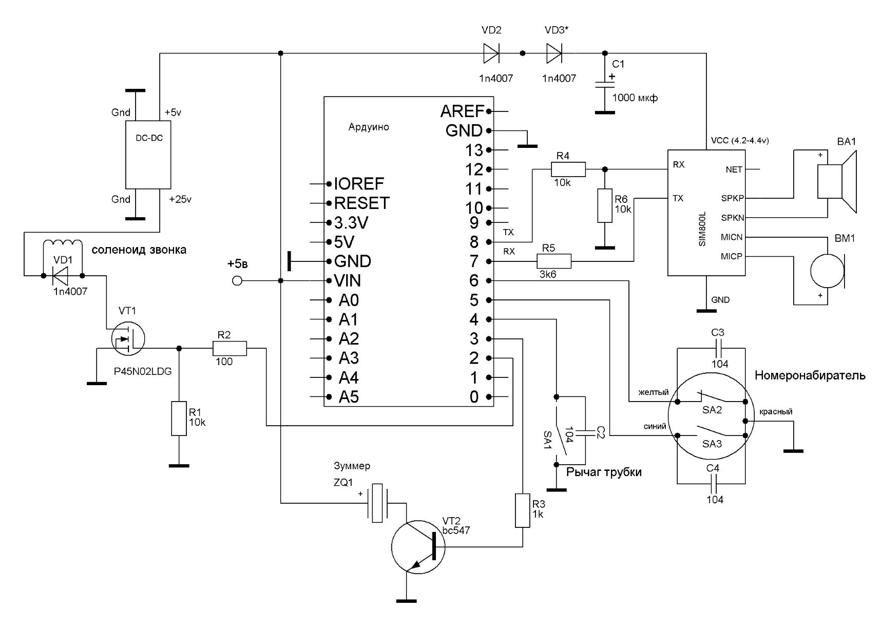
SA1 – это штатный концевой выключатель рычага трубки, в котором используются контакты, которые оказываются замкнуты при положенной на телефон трубке. Для подавления дребезга контакты SA1 зашунтированы конденсатором С2. SA2 – тактирующий контакт номеронабирателя (при начальном положении номеронабирателя — нормально замкнут) , SA3 – шунтирующий контакт (при начальном положении номеронабирателя — нормально разомкнут, при наборе номера — замкнут). Контакты SA2, SA3 также зашунтированы конденсаторами, которые припаиваются прямо на контакты номеронабирателя. Следует отметить, что контакты SA1-SA3 необходимо почистить мелкозернистой шлифовальной бумагой, так как они часто бывают сильно окислены.
На зуммере ZQ1 (транзистор VT2, резистор R3) собирается сигнализатор коротких («занято») и длинного («готов к набору номера») гудков телефона.
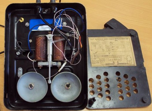
Для сигнализации о звонке используется «родной» звонок телефона, который в большинстве аппаратов собран на соленоиде (электромагнитной катушке). Питание катушки осуществляется через повышающий DC-DC преобразователь, управление — с помощью N-канального логического MOSFET VT1. Можно использовать любой N-канальный логический на соответствующее напряжение, например с материнских плат компьютеров. Для возврата бойка звонка в исходное положение потребуется установить возвратную пружину на привод бойка, что особых сложностей не создает.
В скетче оставлена возможность использовать в качестве звонка сервопривод или электромотор (см. статью Ретро GSM телефон на Arduino …).
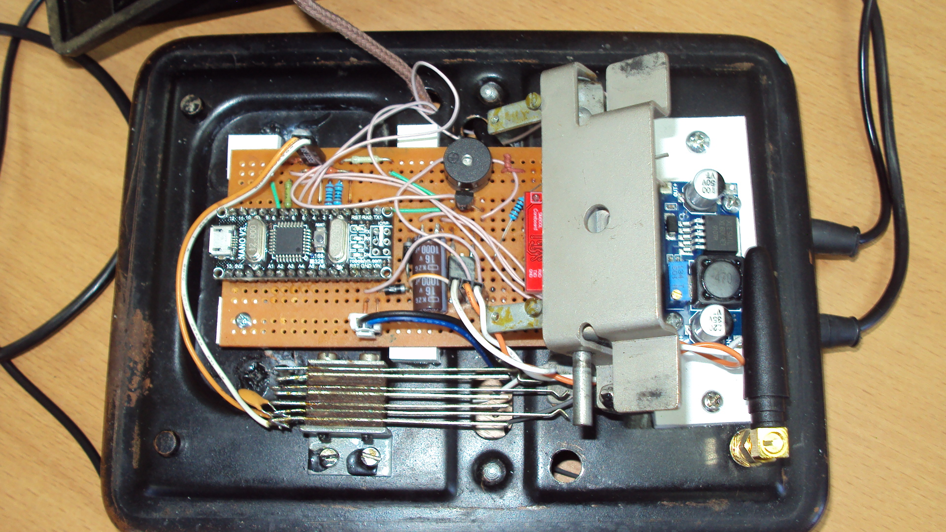
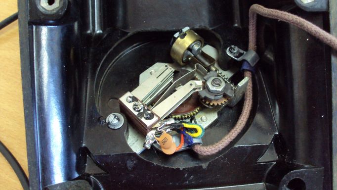
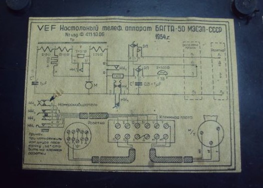
Схема, за исключением динамика, микрофона, рычага трубки, номеронабирателя и DC-DC преобразователя собрана на односторонней макетной плате 8х12 см, которая располагается в удобном месте корпуса телефона, в зависимости от модели. Я использовал корпус телефона «БАГТА-50» 1954 года выпуска.
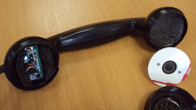
В трубке смонтирован динамик и электретный микрофон. Динамик 0,5-1Вт на 4-8 Ом, микрофон можно использовать от старого сотового телефона. Для соединения аппарата с трубкой лучше использовать экранированный 4-х жильный провод, экран припаять к «-» питания схемы, в крайнем случае — использовать 3-х жильный провод, соединив MICN и SPKN между собой.
Скетч приведен в приложении к статье. Он не содержит нестандартных библиотек, снабжен комментариями, по ходу выполнения скетча служебная информация о происходящем выводится в монитор порта, что позволяет проконтролировать логику работы всей схемы, и, при необходимости, найти ошибку. Для настройки звонка вызова телефона под свою катушку в функции funcBELL(bool f) подберите значения в операторе delay().
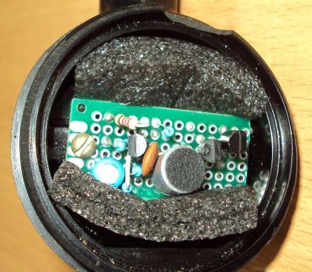
По непонятным причинам, мой экземпляр сим-модуля SIM800L очень плохо усиливал сигнал с микрофона, хотя другие экземпляры данного модуля, которые использовали ребята на радиокружке прекрасно работали (изменение уровня усиления AT-командой не помогало!). Поэтому в схему телефона добавлен микрофонный усилитель на 3-х транзисторах, что решило проблему. Усилитель собран по схеме:
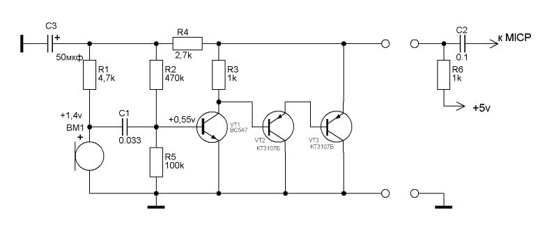
Элементы C2 и R6 монтируются на основную плату, остальные детали — на отдельной плате, вмонтированной в трубку телефона. Для подавления эффекта «самопрослушивания» динамик и микрофон изолируются шумопоглощающим материалом.
Список радиоэлементов
| Обозначение | Тип | Номинал | Количество | Примечание | Магазин | Мой блокнот |
|---|---|---|---|---|---|---|
| Плата Arduino | Arduino Nano 3.0 | 1 | Поиск в магазине Отрон | В блокнот | ||
| SIM800L | 1 | Поиск в магазине Отрон | В блокнот | |||
| DC-DC преобразователь | 1 | +5V—>+25V | Поиск в магазине Отрон | В блокнот | ||
| VD1-VD3 | Выпрямительный диод | 1N4007 | 3 | Поиск в магазине Отрон | В блокнот | |
| VT1 | MOSFET | P45N02LDG | 1 | Поиск в магазине Отрон | В блокнот | |
| VT2 | Биполярный транзистор | BC547 | 1 | Поиск в магазине Отрон | В блокнот | |
| R1, R4, R6 | Резистор | 10 кОм | 3 | Поиск в магазине Отрон | В блокнот | |
| R2 | Резистор | 100 Ом | 1 | Поиск в магазине Отрон | В блокнот | |
| R3 | Резистор | 1 кОм | 1 | Поиск в магазине Отрон | В блокнот | |
| R5 | Резистор | 3.6 кОм | 1 | Поиск в магазине Отрон | В блокнот | |
| C1 | Электролитический конденсатор | 1000 мкф | 1 | Поиск в магазине Отрон | В блокнот | |
| C2-C4 | Конденсатор | 104 | 3 | Поиск в магазине Отрон | В блокнот | |
| ZQ1 | Активный зуммер | 1 | +5V | Поиск в магазине Отрон | В блокнот | |
| BA1 | Динамик | 1 | 0,5-1Вт на 4-8 Ом | Поиск в магазине Отрон | В блокнот | |
| BM1 | Электре́тный микрофон | 1 | Поиск в магазине Отрон | В блокнот | ||
| Усилитель микрофона | ||||||
| VT1 | Биполярный транзистор | BC547 | 1 | Поиск в магазине Отрон | В блокнот | |
| VT2, VT3 | Биполярный транзистор | КТ3107Б | 2 | Поиск в магазине Отрон | В блокнот | |
| R1 | Резистор | 4.7 кОм | 1 | Поиск в магазине Отрон | В блокнот | |
| R2 | Резистор | 470 кОм | 1 | Поиск в магазине Отрон | В блокнот | |
| R3, R6 | Резистор | 1 кОм | 2 | Поиск в магазине Отрон | В блокнот | |
| R4 | Резистор | 2.7 кОм | 1 | Поиск в магазине Отрон | В блокнот | |
| R5 | Резистор | 100 кОм | 1 | Поиск в магазине Отрон | В блокнот | |
| C1 | Конденсатор | 0.033 мкф | 1 | Поиск в магазине Отрон | В блокнот | |
| C2 | Конденсатор | 0.1 мкф | 1 | Поиск в магазине Отрон | В блокнот | |
| C3 | Электролитический конденсатор | 50 мкф | 1 | Поиск в магазине Отрон | В блокнот | |
| Добавить все |
Скачать список элементов (PDF)
Теги:

 Опубликована: 27.07.2022

 1
1
![]()
 Вознаградить
Я собрал
0
3
x
Оценить статью
- Техническая грамотность
- Актуальность материала
- Изложение материала
- Полезность устройства
- Повторяемость устройства
- Орфография
0
Средний балл статьи: 4.7
Проголосовало: 3 чел.